ZD340_07d_e.doc / Apr-17 Page 3 / 50
Table of Contents
1. Available Models................................................................................................................4
2. Introduction.........................................................................................................................6
3. Electrical Connections.........................................................................................................7
3.1. Power Supply ...................................................................................................................9
3.2. Auxiliary Outputs for Encoder Supply..............................................................................9
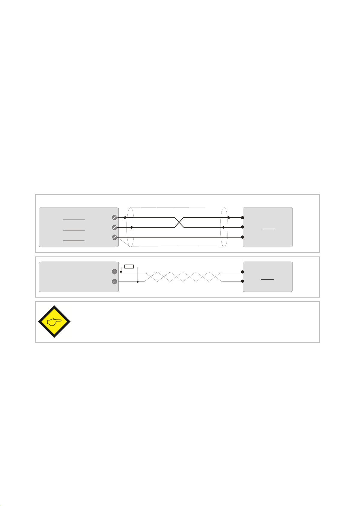
3.3. Impulse Inputs for Incremental Encoders ........................................................................9
3.4. Control Inputs Cont.1 – Cont.4 ........................................................................................9
3.5. Switching Outputs K1 – K4............................................................................................10
3.6. Serial Interface ..............................................................................................................10
3.7. Fast Analogue Output ....................................................................................................10
4. Operating Modes of the Counter.......................................................................................11
4.1. “Single Mode” (Encoder 1 only): F07.062 = 0 ...............................................................12
4.2. “Sum Mode” (Encoder 1 + Encoder 2): F07.062 = 1 ......................................................13
4.3. Differential Mode (Encoder 1 – Encoder 2): F07.062 = 2 ..............................................14
4.4. Master Counter and Integrated Batch Counter: F07.062 = 3 ........................................15
4.5. Evaluation of the Real Cutting Length: F07.062 = 4......................................................16
4.6. Diameter Calculation with Winding Rolls: F07.062 = 5 ................................................17
4.7. Radius Calculation with Winding Rolls: F07.062 = 6 ....................................................18
4.8. Cut-to-Length Control Counter: F07.062 = 7 or 8 ..........................................................19
4.9. Monitor for Slip, Torsion, Skew Position, Shaft Fracture: F07.062 = 9.........................21
4.10. Dual Counter, Two Independent Counters for Encoders 1 and 2: F07.062 = 10 ..........22
5. Keypad Operation .............................................................................................................23
5.1. Normal Operation ..........................................................................................................23
5.2. General Setup Procedure...............................................................................................23
5.3. Direct Fast Access to Presets ........................................................................................24
5.4. Change of Parameter Values on the Numeric Level .....................................................25
5.5. Code Protection against Unauthorized Keypad Access ................................................26
5.6. Return from the Programming Levels and Time-Out Function ......................................26
5.7. Reset all Parameters to Factory Default Values ...........................................................26
6. Menu Structure and Description of Parameters ................................................................27
6.1. Summary of the Menu ...................................................................................................27
6.2. Description of the Parameters.......................................................................................30
6.3. Clarification of the Counter Setting Functions..............................................................39
7. Appendix for models ZD 6xx and ZA 6xx ...........................................................................40
7.1. Relay Outputs.................................................................................................................40
7.2. Front Thumbwheel Switches .........................................................................................40
7.3. Specific Parameters for Units with Thumbwheel Switches .........................................41
8. Appendix: Serial Communication Details ..........................................................................43
8.1. Setup of the Counter by PC............................................................................................43
8.2. Automatic and Cyclic Data Transmission......................................................................44
8.3. Communication Protocol................................................................................................44
8.4. Serial Register Codes ....................................................................................................46
9. Specifications ...................................................................................................................48
10. Dimensions.......................................................................................................................49