DIEBOLD NIXDORF DN 400 Series User manual

DN Series 400
Lobby Multi-Function System
Operator Manual
01750339909C

Table of Contents
1 Introduction ................................................................................................................................ 1-1
1.1 Symbols used in this Manual .............................................................................................1-1
1.2 Section-specific Warning Notes .........................................................................................1-2
1.3 Signs, Labels and Symbols................................................................................................1-3
2 Safety .......................................................................................................................................... 2-1
2.1 General safety precautions for the system.........................................................................2-1
2.2 Radio Interference..............................................................................................................2-4
2.3 General power interruption.................................................................................................2-4
3 Description ................................................................................................................................. 3-1
3.1 System Overview ...............................................................................................................3-1
3.1.1 Overall view......................................................................................................... 3-1
3.1.2 Chassis components........................................................................................... 3-7
3.1.3 Front Door Opened ............................................................................................. 3-9
3.1.4 Component carrier pulled out.............................................................................. 3-10
3.1.5 Cash Components .............................................................................................. 3-20
3.1.6 Fascia Components ............................................................................................ 3-22
3.1.7 Safe components ................................................................................................ 3-31
3.1.8 Cash Components .............................................................................................. 3-37
3.2 External control unit ...........................................................................................................3-39
3.2.1 Functions of the External Control Unit ................................................................ 3-40
3.2.2 LED Codes.......................................................................................................... 3-41
3.3 Card Box (removable) ........................................................................................................3-43
3.4 Card Box (lockable)............................................................................................................3-44
3.5 Remote Status Indicator.....................................................................................................3-45
3.6 Technical data....................................................................................................................3-47
3.6.1 General installation conditions ............................................................................ 3-47
3.6.2 Environmental conditions.................................................................................... 3-50
4 Operation .................................................................................................................................... 4-1
4.1 General Information ...........................................................................................................4-1
4.2 Opening/closing the doors .................................................................................................4-1
4.2.1 Opening/closing the front door............................................................................ 4-2
4.2.2 Opening/closing the rear door............................................................................. 4-4
4.2.3 Opening/Closing the frontload fascia .................................................................. 4-5
4.2.4 Opening/closing the fascia with fascia lock......................................................... 4-6
4.2.5 Opening/closing the operator panel inspection window...................................... 4-8
4.2.6 Opening/Closing the operator panel ................................................................... 4-9
4.3 Starting up / Shutting down the System .............................................................................4-10
4.3.1 Starting up the System........................................................................................ 4-10
4.3.2 Shutting down the System .................................................................................. 4-10
4.4 Starting T/SOP ...................................................................................................................4-11
4.5 Opening/closing the safe door ...........................................................................................4-12
4.5.1 Opening/closing the safe door (with factory setting) ........................................... 4-12
4.5.2 Customizing the key and number combination locks.......................................... 4-18
Copyright © 2020, Diebold Nixdorf
01750339909C
ii

Table of Contents
4.5.3 Opening/closing the safe door (with customized lock)........................................ 4-22
4.6 Calling Up Product-specific Software.................................................................................4-28
4.6.1 Frontload............................................................................................................. 4-28
4.6.2 Rearload with operator panel inspection window (II) .......................................... 4-29
4.6.3 Rearload with operator panel inspection window (I) ........................................... 4-30
4.7 Pulling out/pushing in components ....................................................................................4-31
4.7.1 Pulling out / Pushing in Cash Components......................................................... 4-31
4.7.2 Pulling out/Pushing in Frontload Component Carriers........................................ 4-34
4.7.3 Pulling out/Pushing in Rearload Component Carriers ........................................ 4-37
4.8 Opening/closing the additional latching mechanism of the upper unit ...............................4-40
4.8.1 Opening the additional latching mechanism of the upper unit ............................ 4-40
4.8.2 Closing the additional latching mechanism of the upper unit.............................. 4-41
4.9 Unlocking the physical lock ................................................................................................4-42
4.10 Replacing the logo .............................................................................................................4-42
4.10.1 Branding label fascia........................................................................................... 4-42
4.10.2 Adhesive branding label...................................................................................... 4-45
4.11 Setting the volume of the headphone jack .........................................................................4-46
4.12 Card box (removable) ........................................................................................................4-47
4.12.1 Function elements............................................................................................... 4-47
4.12.2 Emptying the card box (removable) .................................................................... 4-48
4.12.3 Opening the card box.......................................................................................... 4-53
4.12.4 Closing the card box ........................................................................................... 4-54
4.12.5 Pushing in the card box ...................................................................................... 4-55
4.13 Card box (lockable) ............................................................................................................4-56
4.13.1 Function elements............................................................................................... 4-56
4.13.2 Opening the card box.......................................................................................... 4-57
4.13.3 Closing the card box ........................................................................................... 4-58
5 Troubleshooting......................................................................................................................... 5-1
5.1 General Information ...........................................................................................................5-1
5.2 Prerequisites for troubleshooting .......................................................................................5-1
6 Maintenance ............................................................................................................................... 6-1
6.1 Cleaning Housings .............................................................................................................6-1
6.2 Cleaning Keyboards...........................................................................................................6-2
6.3 Cleaning LCD.....................................................................................................................6-2
7 Disposal ...................................................................................................................................... 7-1
8 Appendix..................................................................................................................................... 8-1
8.1 Compliance Standards and Approvals...............................................................................8-1
8.2 Declaration of Conformity...................................................................................................8-3
8.3 Environmental Protection ...................................................................................................8-4
Copyright © 2020, Diebold Nixdorf
01750339909C
iii

Table of Contents
List of Figures
Figure 2-1 Switching off the system.........................................................................................2-5
Figure 2-2 General power interruption - Disconnecting the plug .............................................2-5
Figure 3-1 Frontload overall view ............................................................................................3-1
Figure 3-2 Rearload overall view .............................................................................................3-2
Figure 3-3 Rear view with operator panel inspection window .................................................3-3
Figure 3-4 Rear view with operator panel keyboard................................................................3-4
Figure 3-5 Illuminated privacy panel........................................................................................3-5
Figure 3-6 Overall view with electromechanical locking ..........................................................3-6
Figure 3-7 Fascia open............................................................................................................3-7
Figure 3-8 Rear door opened - without operator panel inspection window .............................3-8
Figure 3-9 Component carrier pulled out.................................................................................3-10
Figure 3-10 Component carrier with CDM pulled out ................................................................3-11
Figure 3-11 Component carrier with coin module pulled out .....................................................3-12
Figure 3-12 Component carrier pulled out – with Passbook Printer ..........................................3-13
Figure 3-13 Upper component carrier pulled out.......................................................................3-14
Figure 3-14 Component carrier pulled out — rearload ..............................................................3-15
Figure 3-15 Component carrier with CDM pulled out — rearload..............................................3-16
Figure 3-16 Component carrier with coin module pulled out — rearload ..................................3-17
Figure 3-17 Upper component carrier pulled out — rearload ...................................................3-18
Figure 3-18 Upper component carrier pulled out — rearload ...................................................3-19
Figure 3-19 Upper Unit ..............................................................................................................3-20
Figure 3-20 Lower Unit ..............................................................................................................3-21
Figure 3-21 15" version, broadside format with functions keys .................................................3-23
Figure 3-22 15” version, broadside format with function keys and coin dispenser....................3-24
Figure 3-23 15" version, broadside format with check deposit module and passbook printer...3-25
Figure 3-24 19" version, portrait format without function keys, with coin dispenser ..................3-26
Figure 3-25 19” version, broadside format with CDM and coin dispenser.................................3-27
Figure 3-26 Version 15" with function keys - Rearload..............................................................3-28
Figure 3-27 Guide lights ............................................................................................................3-29
Figure 3-28 Keyboard privacy shield .........................................................................................3-30
Figure 3-29 Safe opened with RM4V - Frontload ......................................................................3-31
Figure 3-30 Safe opened with RM4H - Frontload......................................................................3-32
Figure 3-31 Safe opened with CMD-V6C - Frontload................................................................3-33
Figure 3-32 Safe opened with RM4V - Rearload.......................................................................3-34
Figure 3-33 Safe opened with RM4H - Rearload.......................................................................3-35
Figure 3-34 Safe opened with CMD-V6C - Rearload ................................................................3-36
Figure 3-35 Upper Unit ..............................................................................................................3-37
Figure 3-36 Lower Unit ..............................................................................................................3-38
Figure 3-37 External Control Unit - Overview ............................................................................3-39
Figure 3-38 Removable card box ..............................................................................................3-43
Figure 3-39 Lockable card box ..................................................................................................3-44
Copyright © 2020, Diebold Nixdorf
01750339909C
iv

Table of Contents
Figure 4-1 Opening the frontload front door ............................................................................4-2
Figure 4-2 Opening the frontload front door ............................................................................4-2
Figure 4-3 Closing the frontload front door..............................................................................4-3
Figure 4-4 Locking the frontload front door with a key ............................................................4-3
Figure 4-5 Opening the rear door ............................................................................................4-4
Figure 4-6 Opening the fascia .................................................................................................4-5
Figure 4-7 Releasing the lever under the fascia......................................................................4-5
Figure 4-8 Closing the fascia...................................................................................................4-6
Figure 4-9 Opening the fascia lock..........................................................................................4-6
Figure 4-10 Opening the fascia with fascia lock ........................................................................4-7
Figure 4-11 Closing the fascia with fascia lock..........................................................................4-7
Figure 4-12 Unlocking the operator panel inspection window ...................................................4-8
Figure 4-13 Opening the operator panel inspection window .....................................................4-8
Figure 4-14 Opening/closing the operator panel .......................................................................4-9
Figure 4-15 Switching off the System........................................................................................4-10
Figure 4-16 Turning off the System ...........................................................................................4-11
Figure 4-17 Calling the T/SOP...................................................................................................4-11
Figure 4-18 Press the SOP button on the external control unit .................................................4-28
Figure 4-19 Unlocking the operator panel inspection window ...................................................4-29
Figure 4-20 Rearload with inspection window - Calling up SOP ...............................................4-29
Figure 4-21 Unlocking the operator panel inspection window ...................................................4-30
Figure 4-22 Pulling out the Upper Unit ......................................................................................4-31
Figure 4-23 Pushing in the Upper Unit ......................................................................................4-32
Figure 4-24 Pulling out the Lower Unit ......................................................................................4-32
Figure 4-25 Pushing in the Lower Unit ......................................................................................4-33
Figure 4-26 Pulling out the upper component carriers – frontload ............................................4-34
Figure 4-27 Pulling out the upper component carrier (with passbook printer) – frontload.........4-35
Figure 4-28 Pulling out the lower component unit — frontload..................................................4-36
Figure 4-29 Pulling out the upper component carriers - rearload ..............................................4-37
Figure 4-30 Pulling out the upper component carriers (with passbook printer) - rearload.........4-38
Figure 4-31 Pulling out the lower component carrier — rearload ..............................................4-39
Figure 4-32 Opening the additional latching mechanism of the upper unit ...............................4-40
Figure 4-33 Pulling the upper unit forwards...............................................................................4-41
Figure 4-34 Unlocking the physical lock - Frontload..................................................................4-42
Figure 4-35 Dimensions of the branding label fascia.................................................................4-43
Figure 4-36 Branding label - Loosening clips ............................................................................4-43
Figure 4-37 Replacing the branding label..................................................................................4-44
Figure 4-38 Branding label - Closing clips.................................................................................4-44
Figure 4-39 Dimensions of the adhesive branding label ...........................................................4-45
Figure 4-40 Recess for the adhesive branding label .................................................................4-45
Figure 4-41 Setting the headphone jack volume .......................................................................4-46
Figure 4-42 Function elements - Lockable card box..................................................................4-47
Copyright © 2020, Diebold Nixdorf
01750339909C
v

Table of Contents
Figure 4-43 Pulling out the removable card box........................................................................4-48
Figure 4-44 Unlocking the removable card box.........................................................................4-49
Figure 4-45 Opening the removable card box ...........................................................................4-49
Figure 4-46 Removable card box – Removing cards ................................................................4-50
Figure 4-47 Closing the removable card box.............................................................................4-51
Figure 4-48 Locking the removable card box ............................................................................4-51
Figure 4-49 Pushing in the removable card box........................................................................4-52
Figure 4-50 Unlocking the removable card box.........................................................................4-53
Figure 4-51 Opening the removable card box ...........................................................................4-53
Figure 4-52 Removable card box – Removing cards ................................................................4-54
Figure 4-53 Closing the removable card box.............................................................................4-54
Figure 4-54 Locking the removable card box ............................................................................4-55
Figure 4-55 Pushing in the removable card box........................................................................4-55
Figure 4-56 Function elements - Lockable card box..................................................................4-56
Figure 4-57 Unlocking the lockable card box.............................................................................4-57
Figure 4-58 Opening the lockable card box...............................................................................4-57
Figure 4-59 Lockable card box – Removing cards ....................................................................4-58
Figure 4-60 Closing the lockable card box ................................................................................4-58
Figure 4-61 Locking the lockable card box................................................................................4-59
Copyright © 2020, Diebold Nixdorf
01750339909C
vi

Table of Contents
List of Tables
Table 1-1 Warning signs used................................................................................................1-3
Table 1-2 Used mandatory signs............................................................................................1-3
Table 3-1 Functions of the On/Off button ...............................................................................3-40
Table 3-2 Electrical characteristics of the supply network......................................................3-47
Table 3-3 System conditions ..................................................................................................3-48
Table 3-4 Installation specifications........................................................................................3-49
Table 3-5 Climatic environmental conditions..........................................................................3-50
Table 3-6 Noise emissions .....................................................................................................3-50
Table 6-1 Approved cleaning agents for the housing.............................................................6-1
Table 6-2 Approved cleaning agents for keyboards...............................................................6-2
Table 6-3 Approved cleaning agents for the LCD .................................................................6-2
Copyright © 2020, Diebold Nixdorf
01750339909C
vii

1
1 Introduction
This operator manual is intended to make it easier for you to get to know the Systemand to use it for its
intended purpose.
This operator manual contain important information for the safe, proper and economical operation of the
system. Observing them helps to reduce risks, repair costs and downtimes and to increase reliability and
service life.
Existing national regulations on accident prevention and environmental protection also apply.
The operator should ensure that every person working with or on the system reads and applies this oper-
ator manual.
This operator manual must be kept in a known and easily accessible place and must be consulted even
in the event of the slightest doubt.
1.1
1.1 Symbols used in this Manual
●Text following a dash represents an item in a list.
"" Refers to other chapters or sections.
'' Text in apostrophes relates to equipment/mounting parts which are included
in the delivery package.
Text Texts in small capitals designate pushbuttons/switches on a control or
switches that are to be actuated in the software.
1.
2.
n.
Numbered procedural instructions describe activities which must be carried
out in the specified order.
Copyright © 2020, Diebold Nixdorf
01750339909C
1-1

Introduction
1.2
1.2 Section-specific Warning Notes
DANGER
This warning note describes a hazard with a high degree of risk which, if not avoided, will
result in death or grave bodily injury.
WARNING
This warning note describes a hazard with a medium degree of risk which, if not avoided,
could result in death or grave bodily injury.
CAUTION
This warning note describes a hazard with a low degree of risk which, if not avoided, could
result in slight or minor bodily injury.
NOTE
This note provides application tips and information that help prevent errors and material
damage.
Copyright © 2020, Diebold Nixdorf
01750339909C
1-2
Introduction
1.3
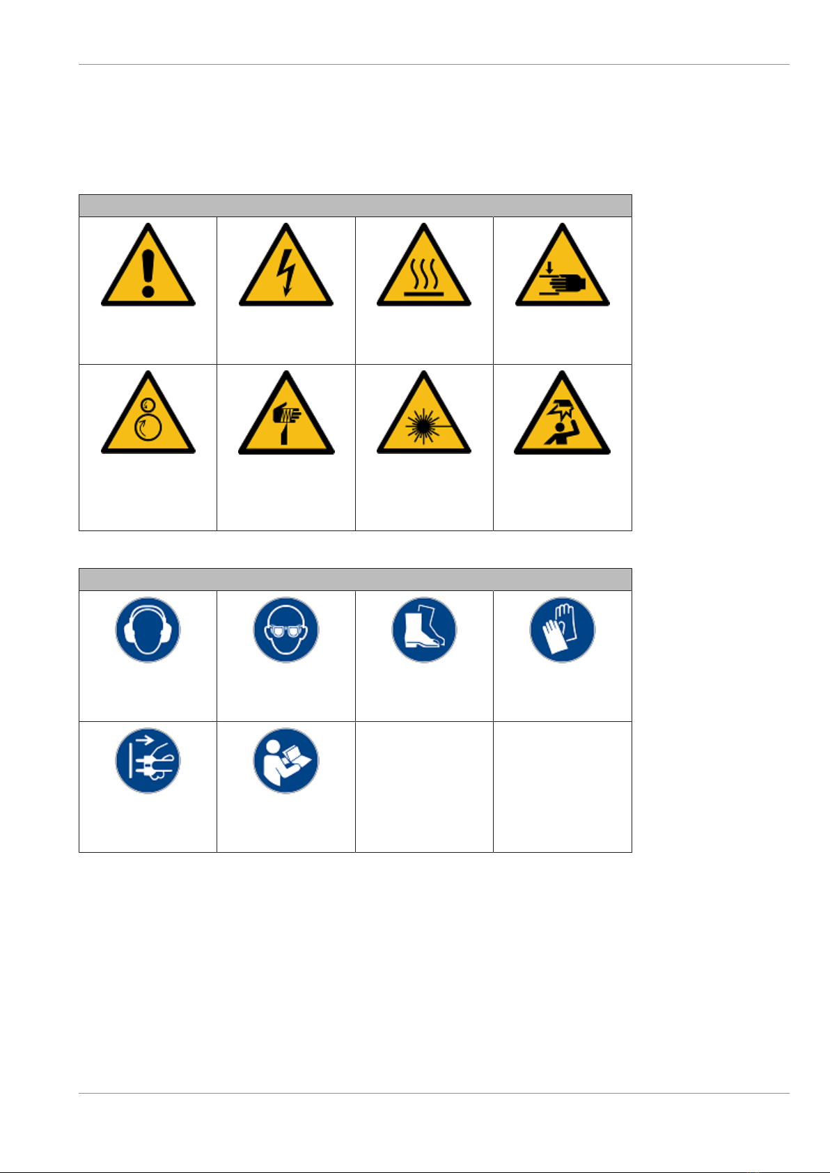
1.3 Signs, Labels and Symbols
The following labels can be used in these instructions, on the system or on the component.
Table1-1: Warning signs used
Warning signs
General
warning sign
Warning of
electric voltage
Warning of
hot surfaces
Warning of
hand injuries
Warning of
feed risk
Warning of
cut injuries
Warning of
laser beam
Warning of
obstacles in the
head area
Table1-2: Used mandatory signs
Mandatory signs
Use
hearing protection
Use
protection eyewear
Use
safety footwear
Use
protective gloves
Pull
main plug
Read
manual
Copyright © 2020, Diebold Nixdorf
01750339909C
1-3

2
2 Safety
2.1
2.1 General safety precautions for the system
This system complies with the relevant safety regulations for information processing equipment.
NOTE
Read this entire manual carefully in order to obtain a thorough knowledge with respect to
the system and the components, in addition to their operation and maintenance.
Operate the system and the components correctly in accordance with this manual in order
to avoid injuries and damage.
Keep this manual available and consult it for guidance when you are unsure about how to
carry out one or another of the procedures.
DANGER
Electrical voltage
Risk of fatal injury through contact with parts carrying electrical voltage! Switch the system
off before performing any cleaning or maintenance tasks.
lSwitch off the power switch for the power distributor.
lSwitch off the UPS, if installed.
lDisconnect the mains connection, if installed, between the UPS (Uninterruptible
Power Supply) and the system itself (see section "General power interruption" in the
operating manual).
lDisconnect the connector of the power supply cable from the electrical socket in-
stalled by the building contractor.
DANGER
Electrical voltage
Risk of fatal injury through contact with parts carrying electrical voltage! Before cleaning
and maintenance work, disconnect the system from the main power supply (for details see
Section2.3)
lSwitch off the system (see chapter "Operation",
section "Switching the system on/off).
lDisconnect the connector of the power supply cable from the electrical socket in-
stalled by the building contractor.
Copyright © 2020, Diebold Nixdorf
01750339909C
2-1
Safety
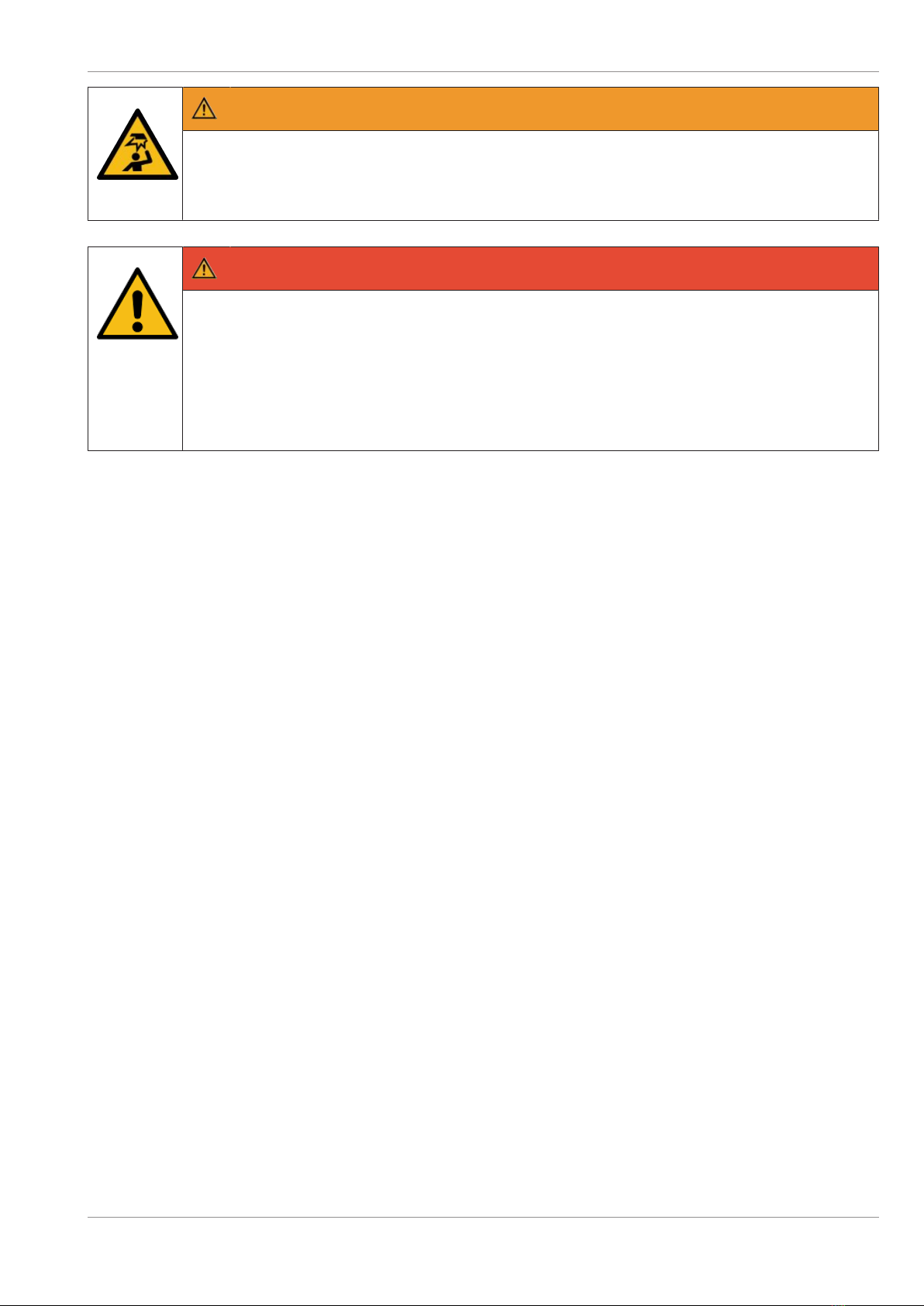
WARNING
Risk of impact
Be careful not to injure your head when the fascia or rear door is opened.
lMove carefully when the control panel or the rear door is opened.
DANGER
Adverse weather conditions
Make sure that no water/liquids (e.g. rain, snow etc.) gets into the open system and the
exposed components, especially under adverse weather conditions, since that could pose
a danger to your life.
Be sure to take suitable precautions when working on an open system (e.g. by covering
components where necessary) so that fluid cannot enter the open system.
• For reasons of stability, the system must be screwed to the load-bearing substructure of the installa-
tion site or mounted on a suitable base.
• When moving the system from a cold to a warm environment, condensations might occur. Therefore
consider an acclimatization time of at least two hours, before you connect the system to the supply
voltage.
• Only use the original packaging material to transport the system.
• Observe the warning and information labels on the system.
• Unless otherwise stated, grasp the components only by the green control elements when handling
them.
• This system is equipped with a safety-tested power cable which must be connected to a suitable
grounded socket only.
• Always hold the plug when removing the power cable. Never pull on the cable itself.
• Lay all connecting cables in such a way that they will not be stepped on or tripped over, damaged or
crushed in any way.
• Have damaged power cables replaced immediately.
• Make sure that there is always free access to the electrical sockets used or to the electrical circuit-
breakers of the facility installation.
Copyright © 2020, Diebold Nixdorf
01750339909C
2-2

Safety
DANGER
In case of an emergency (e.g. damaged cabinets, controls or power cables, liquids or for-
eign objects in the system) take the following steps:
Switch the system voltage-free immediately by:
lSwitching off the automatic circuit breaker or removing the fuse insert from the fuse
holder in the distributor box of the facility installation.
lDisconnecting the plug of the power supply cable from the grounded socket in the fa-
cility installation.
lInterrupting the power connection between the UPS (uninterruptible power supply)
and the system (see chapter "Introduction", section "General power interruption" in
the operating manual);
lFor further system-specific notes, please refer to the operating manuals.
lInform the customer service responsible for you.
• Never connect or disconnect data transmission lines during a thunderstorm.
• Always keep the system’s ventilation openings free from obstruction to ensure proper ventilation and
to prevent malfunctions resulting from overheating.
• Use only accessories and extension components that have been approved by . Nonobservance can
result in damage to the system or violations of regulations concerning safety, radio interference and
ergonomical requirements.
• Note that there are only safety extra-low voltage circuits (SELV circuits) if you want to feed voltage
from an external source into prepared cables to install additional electronics (e. g. EMA connection).
• To clean the system only use cleaning agents approved by Diebold Nixdorf (see chapter "Cleaning,
Service and Maintenance" in the operating manual).
• Components with adjustable light effects are integrated in this product. Repetition frequencies be-
tween 5 Hz and 40 Hz should be avoided as certain light frequencies or flickering light sources can
cause epileptic seizures in some individuals.
Also avoid light reflections and synchronize the cycles wherever possible. Ensure that monitors' re-
fresh rates are as high as possible.
DANGER
Repairs
Repair work on the system or on the components may be carried out only by authorized
specialist staff. Unauthorized opening of the system or repair work carried out improperly
could result in considerable danger to the user.
In case of noncompliance, excludes all liability.
Copyright © 2020, Diebold Nixdorf
01750339909C
2-3
Safety
Lithium batteries
DANGER
Danger of fire and explosion
The handling and replacement of batteries should only be performed by authorized per-
sonnel trained by trained or authorized service personnel.
There is danger of fire or explosion if the batteries are handled improperly. It is therefore
important to note the following points:
lAvoid short circuits
lNever recharge the battery
lAvoid temperatures above +100°C (+212°F).
lDo not attempt to open the battery by force
lDo not allow the battery to come into contact with water or fire
lThe battery should only be replaced with the same or an equivalent type recom-
mended by (see chapter “Appendix,” section “Consumables” in the operating man-
ual). Dispose of used batteries in compliance with national regulations and the manu-
facturer's specifications.
2.2
2.2 Radio Interference
WARNING
This is a class A product. In a domestic environment this product may cause radio interfer-
ence, in which case the user may be required to take adequate measures.
A warning label is included on systems available in Taiwan to meet Taiwan Class A regulatory require-
ments for radio frequency interference.
2.3
2.3 General power interruption
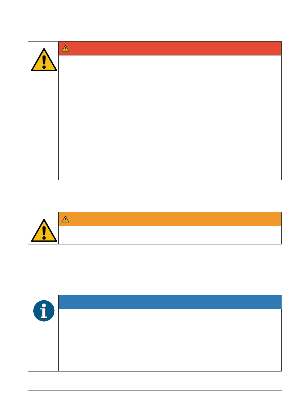
NOTE
A general power interruption has the following effects:
– Transactions in progress are canceled immediately (exception: ID card transport).
– Dispensed banknotes remain in the transport routes of the cash media dispenser. They
are transported to the clamp's stacking position or the cash media dispenser's reject cas-
sette when the system is switched on again.
– Depending on the parameter setting, ID cards are either output, retained or transported
to the card reject tray. This transaction will be completed properly.
Copyright © 2020, Diebold Nixdorf
01750339909C
2-4

Safety
1. Access the external control unit (see Operator Manual, chapter "System overview", section "Chas-
sis components").
Figure2-1: Switching off the system
2. Switch the system off with the ON/OFF but-
ton of the external control unit (1).
Figure2-2: General power interruption - Disconnecting the
plug
üThe type of plug used may differ depending
on the country of origin.
3. To ensure the power supply is fully discon-
nected, disconnect the power supply cable
from the electrical socket (1).
Alternatively, the power supply can be interrupted
by switching off the circuit-breaker or removing
the fuse from the distributor box of the facility in-
stallation.
Copyright © 2020, Diebold Nixdorf
01750339909C
2-5
3
3 Description
3.1
3.1 System Overview
3.1.1
3.1.1 Overall view
3.1.1.1
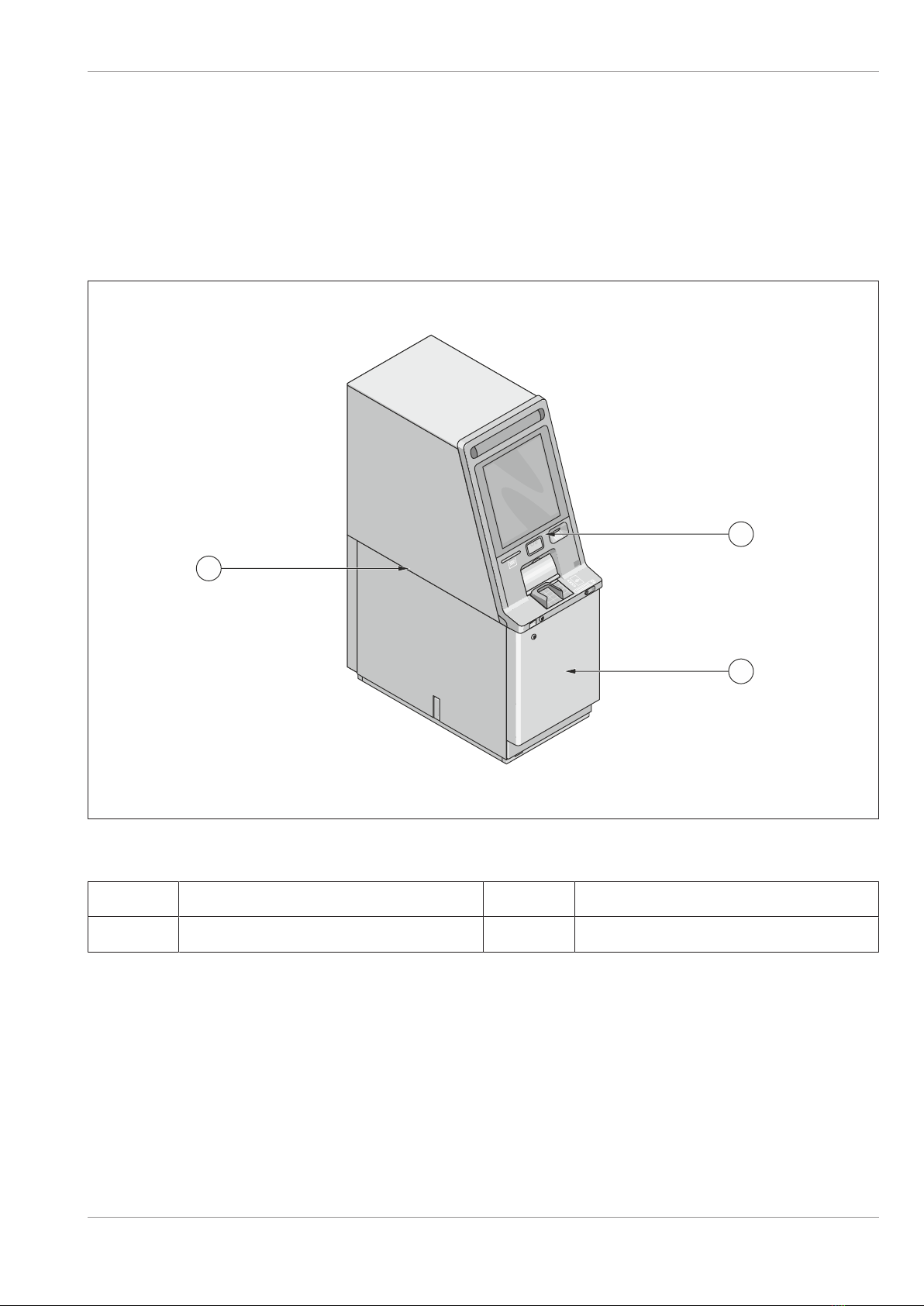
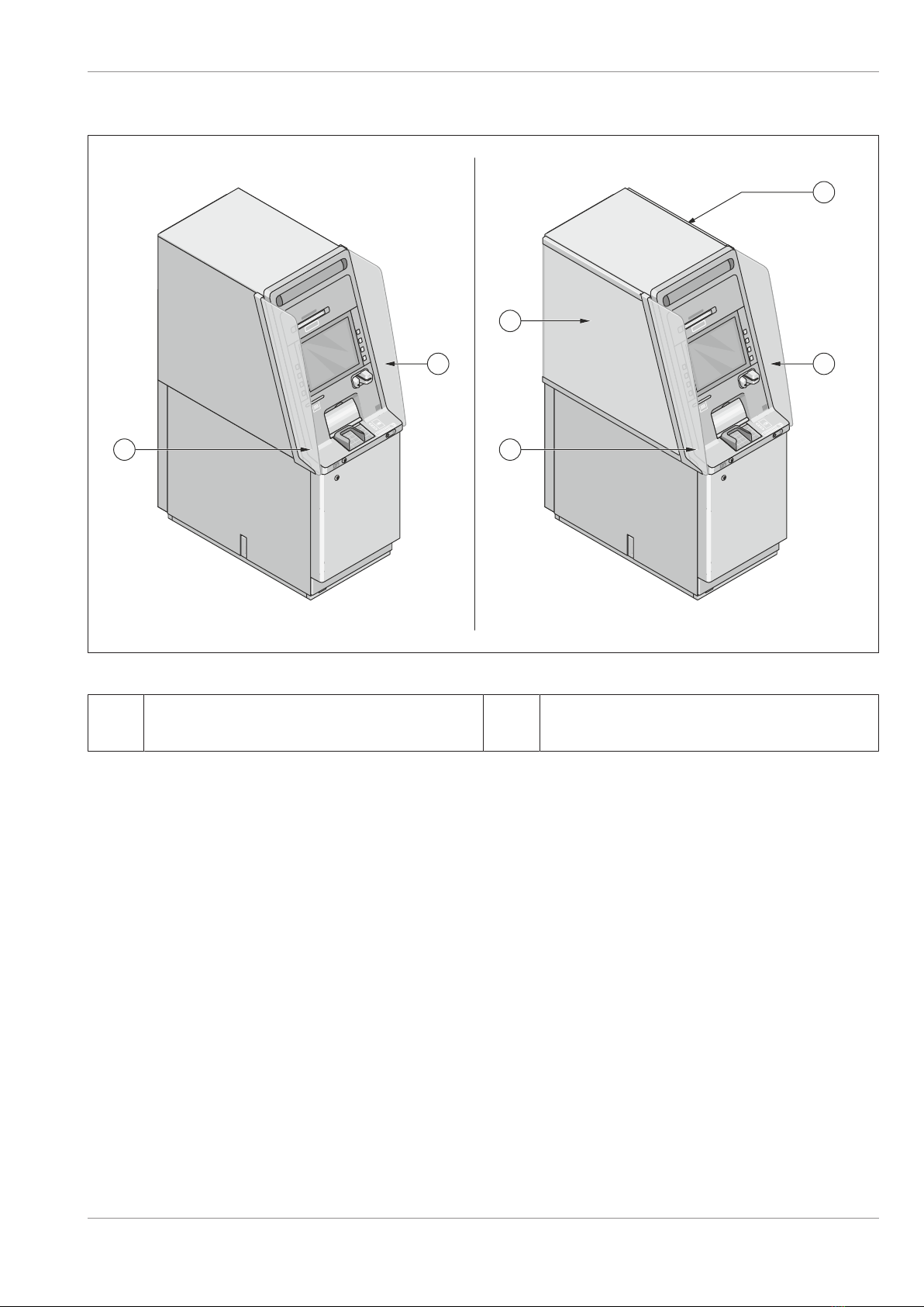
3.1.1.1 Overall view, Frontload from the front
TEST LF PE ERROR POWER
USB POWER
2
1
3
TD-01574-65
Figure3-1: Frontload overall view
1System 3Front door
2Fascia
Copyright © 2020, Diebold Nixdorf
01750339909C
3-1

Description
3.1.1.2
3.1.1.2 Overall view, Rearload from the front
TEST LF PE ERROR POWER
USB POWER
2
1
3
TD-01574-66
Figure3-2: Rearload overall view
1System 3Front door
2Fascia
Copyright © 2020, Diebold Nixdorf
01750339909C
3-2
Description
3.1.1.3
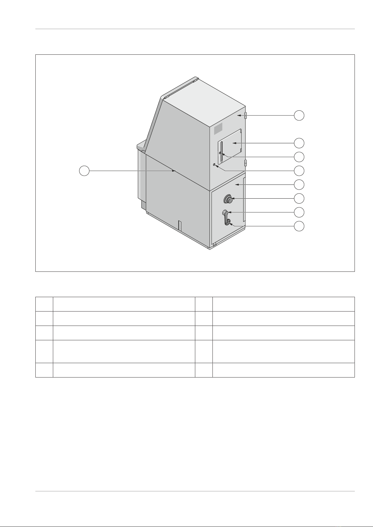
3.1.1.3 Overall view from the rear (with Operator Panel Inspection Window)
4
1
8
2
3
5
6
7
9
TD-01574-67
Figure3-3: Rear view with operator panel inspection window
1System 6Safe door
2Rear door 7Number combination lock
3Operator panel inspection window (optional) 8Locking/release handle of safe
4Lock for the operator panel inspection win-
dow (optional)
9Key-operated lock
5Rear door lock
Copyright © 2020, Diebold Nixdorf
01750339909C
3-3

Description
3.1.1.4
3.1.1.4 Overall view from the rear (with Passbook Printer)
4
1
8
2
3
5
6
7
9
TD-01574-160
Figure3-4: Rear view with operator panel keyboard
1System 6Safe door
2Passbook printer 7Number combination lock
3Operator panel inspection window (optional) 8Locking/release handle of safe
4Lock for the operator panel inspection win-
dow (optional)
9Key-operated lock
5Rear door lock
Copyright © 2020, Diebold Nixdorf
01750339909C
3-4
Description
3.1.1.5
3.1.1.5 Illuminated privacy panel
2
1 1
1
2
1
TD-01574-161
Figure3-5: Illuminated privacy panel
1Illuminated privacy panel, fascia 2Illuminated privacy panel, top of the chas-
sis
Copyright © 2020, Diebold Nixdorf
01750339909C
3-5
Table of contents
Other DIEBOLD NIXDORF Cash Counter manuals

DIEBOLD NIXDORF
DIEBOLD NIXDORF DN 490 User manual

DIEBOLD NIXDORF
DIEBOLD NIXDORF CS 7700 User manual

DIEBOLD NIXDORF
DIEBOLD NIXDORF DN Series 100D FL User manual

DIEBOLD NIXDORF
DIEBOLD NIXDORF CINEO C4060 Installation instructions

DIEBOLD NIXDORF
DIEBOLD NIXDORF CS 7790 User manual

DIEBOLD NIXDORF
DIEBOLD NIXDORF CS 7750 User manual

DIEBOLD NIXDORF
DIEBOLD NIXDORF DN 250 Series User manual

DIEBOLD NIXDORF
DIEBOLD NIXDORF CS 5500 User manual

DIEBOLD NIXDORF
DIEBOLD NIXDORF CS 5500 User manual

DIEBOLD NIXDORF
DIEBOLD NIXDORF CS 7780 User manual


