SEI Industries HELI-PUMP User manual

Heli-PUMP
oPerations
ManUal
2020 VERSION F

2020 Heli-Pump Operations Manual (Version F)
We Engineer Solutions
HELI-PUMP OPERATIONS MANUAL - Version F
Issue Date: February 2020
PLEASE READ BEFORE USING.
SEI INDUSTRIES LTD.
7400 Wilson Avenue
Delta, B.C. Canada
V4G 1H3
Phone: (604) 946-3131
Fax: (604) 940-9566
E-Mail: [email protected]
Website: www.sei-ind.com
COPYRIGHT © 2020 SEI INDUSTRIES LTD. ALL RIGHTS RESERVED
PRINTED IN CANADA

2020 Heli-Pump Operations Manual (Version F)
We Engineer Solutions
Table of Contents
Section 1: Heli-Pump Overview 1
Introduction ...................................................................................................................1
Description of Pump Systems ........................................................................1
Features and Options .....................................................................................1
Available Models ............................................................................................ 1
Model Specifications .....................................................................................................2
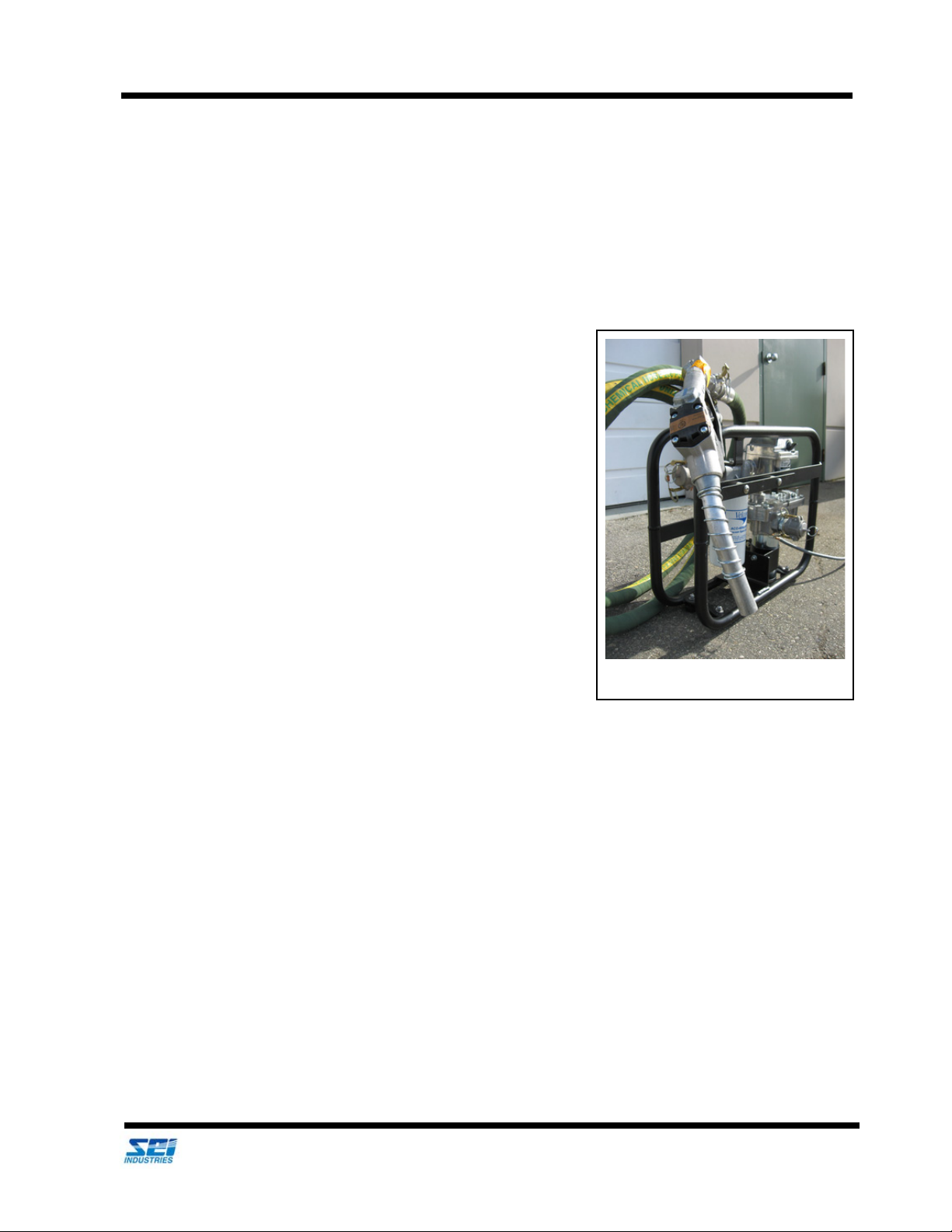
Model Slimline Pump, Part # 003530 .............................................................2
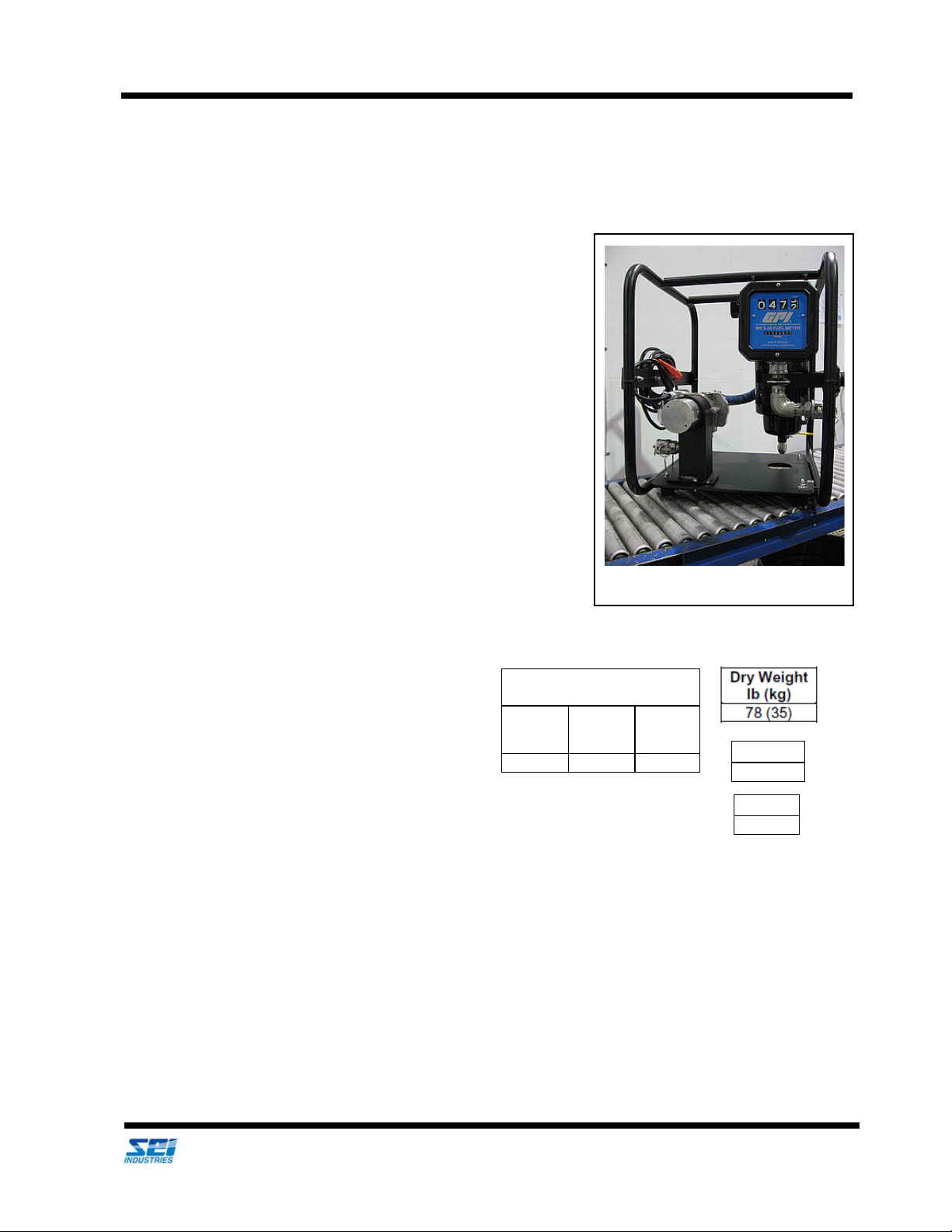
Model PSHR 1210 Heli-Pump, Part # 003595 ...............................................3
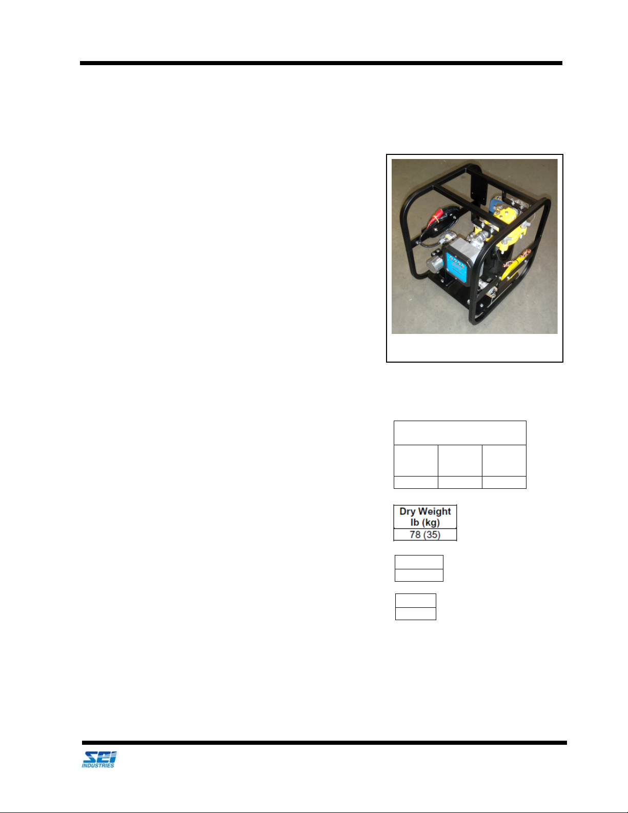
Model PSHR 2410 Heli-Pump, Part # 003594 ...............................................4
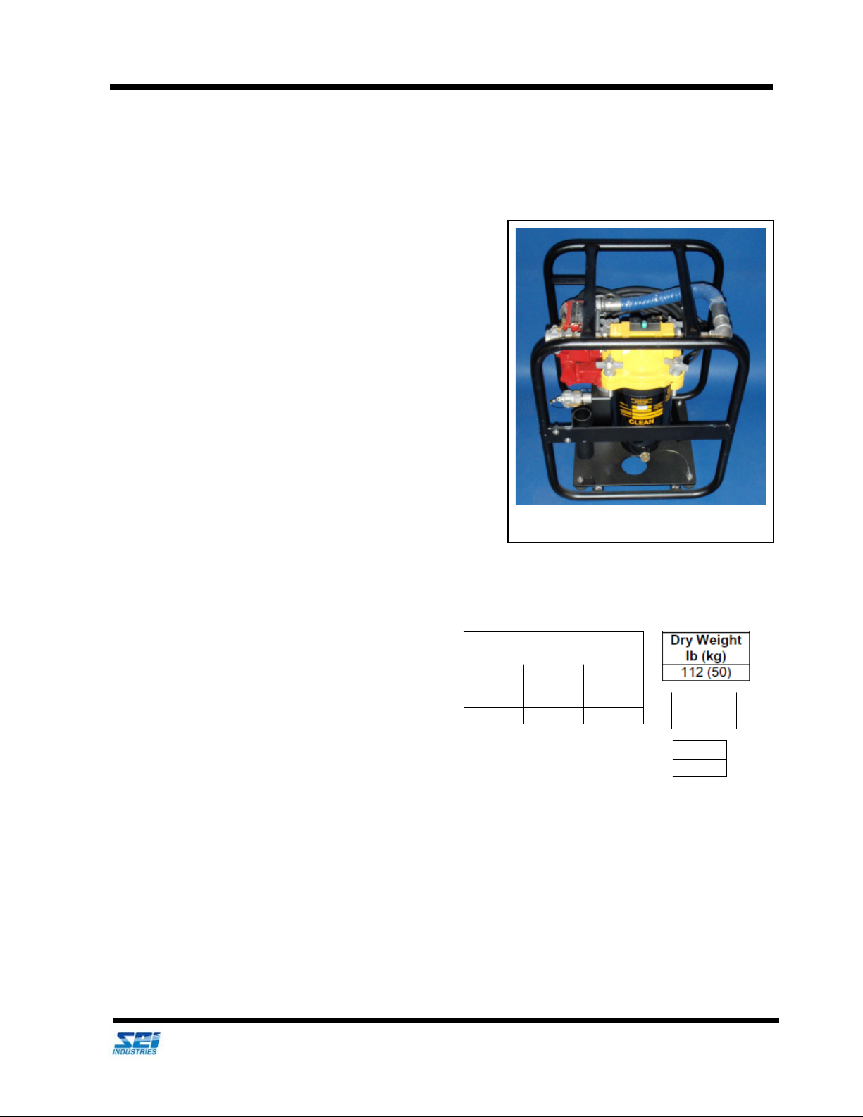
Model PSHR 2420 Heli-Pump, Part # 003687 ...............................................5
Model PSHR 2420-2 Heli-Pump, Part # 009923 ............................................6
Model PSHR 23020 Heli-Pump AC, Part # 003687A .....................................7
Model PSHR 11020 Heli-Pump AC, Part # 003687B .....................................8
Model PSD 688 Maritime Pump, Part # 006647 .............................................9
Section 2: Pump Safety 10
Safety Procedures ......................................................................................................10
Installation .................................................................................................... 10
Operation ......................................................................................................10
Service ..........................................................................................................11
Section 3: Pump Operations 12
12/24 VDC and 110/230 VAC Operations ..................................................................12
Dispensing Fuel ............................................................................................13
Filter Instructions ........................................................................................................13
Filter Safety Precautions ..............................................................................14
Models Slimline, PSHR 2410 and 1210 Pumps .........................................................15
Priming .........................................................................................................15
Motor Protector .............................................................................................16
Pump Maintenance .......................................................................................16
Models PSHR 2420, 2420-2, 11020 and 23020 Pumps .............................................18
Model PSD 688 Pump ................................................................................................19
PSD 688 Maintenance ..................................................................................19
Priming All Pump Systems .........................................................................................21
Section 4: Fuel Meters 22
Operations and Maintenance .....................................................................................22
Meter Accuracy .............................................................................................22
Daily Operations ...........................................................................................22
Maintenance .................................................................................................23

2020 Heli-Pump Operations Manual (Version F)
We Engineer Solutions
Section 5: Filters 24
Filter Safety ................................................................................................................24
Safety Precautions .......................................................................................24
Models Slimline, PSHR 2410 and PSD 688 Filters ....................................................25
Models PSHR 1210, 2420, 11020 and 23020 Filters .................................................26
Model PSHR 2420-2 Filter ..........................................................................................27
Filter Maintenance ......................................................................................................28
Cartridge Replacement .................................................................................28
Section 6: Parts 31
Part Lists .....................................................................................................................31
Model Slimline, Part # 003530 ......................................................................31
Model PSHR 1210 Heli-Pump, Part # 003595 .............................................32
Model PSHR 2410 Heli-Pump, Part # 003594 .............................................33
Model PSHR 2420 Heli-Pump, Part # 003687 .............................................34
Model PSHR 2420-2 Heli-Pump, Part # 009923 ..........................................35
Model PSHR 23020 Heli-Pump, Part # 03687A ...........................................36
Model PSHR 11020 Heli-Pump, Part # 03687B ...........................................37
Model PSD 688 Maritime Pump, Part # 006647 ...........................................38
Accessories ..................................................................................................39
Slimline and Maritime Pump Filters ..............................................................40
PSHR 2410, 2420, 1210, 11020 and 23020 Pump Filters ............................40
PSHR 2420-2 Pump Filter ............................................................................40
Section 7: Warranty 41
Appendix 42
Contents .....................................................................................................................42

Section 1: Heli-Pump Overview Introduction
2020 Heli-Pump Operations Manual (Version F) 1
We Engineer Solutions
Section 1: Heli-Pump Overview
Introduction
Description of Pump Systems
Designed for military special forces and adapted for civilian
helicopter operators, the Heli-Pump is a complete turnkey electric
aviation fuel pumping system in a compact package. Designed for
rapid deployment, Heli-Pumps can distribute fuel from SEI’s
collapsible bladder tanks or Fuel-Easy container as well as steel
tanks or drums.
With a variety of models to choose from, the Heli-Pump is powered
by a helicopter’s DC system. Ideal for remote site operations, the
Heli-Pump fits inside the cargo area of most helicopters. The Heli-
Pump series includes models that use 24VDC, one model that uses
110 or 230 VAC and two models that use 12 VDC (including one that
is a marine version). Most models offer single-stage filtration while
one model offers dual-stage filtration.
Features and Options
• Small, lightweight package.
• Transportable and storable.
• Complete aviation refuelling system.
• Optional Fuel-Easy camlock adapter kit.
• Optional Electrical plug connection (customer must provide specs).
Available Models
• PSHR Slimline: 10 USGPM (37 LPM) 10 amps 24 VDC (Part # 003530)
• PSHR 1210 Heli-Pump: 11 USGPM (40 LPM) 18 amps 12 VDC (Part # 003595)
• PSHR 2410 Heli-Pump 11 USGPM (40 LPM) 10 amps 24 VDC (Part # 003594)
• PSHR 2420 Heli-Pump: 20 USGPM (75 LPM) 20 amps 24 VDC (Part # 003687)
• PSHR 2420-2 Heli-Pump: 20 USGPM (75 LPM) 20 amps 24 VDC (Part # 009923)
• PSHR 23020 Heli-Pump AC: 20 USGPM (75 LPM) 2.3 amps 230 VAC (Part # 003687A)
• PSHR 11020 Heli-Pump AC: 20 USGPM (75 LPM) 4.9 amps 110 VAC (Part # 003687B)
• PSD 688 Maritime Pump: 10 USGPM (37 LPM) 10 amps 12 VDC (Part # 006647)
Slimline pump (not in carrying case).

Section 1: Heli-Pump Overview Model Specifications
2020 Heli-Pump Operations Manual (Version F) 2
We Engineer Solutions
Model Specifications
Model Slimline Pump, Part # 003530
Standard Equipment List
1. 10 USGPM (37 LPM) 24 VDC, 10 AMP
electric pump.
2. Replaceable absorbent cartridge filter
3. Leak-proof hard carrying case with lock.
4. 12 ft. of 1” discharge hose with nozzle.
5. 12 ft. of 1” suction hose with camlocks.
6. Totalizing flow meter.
7. Camlock connection drum stub.
8. 20 ft. grounding wire.
9. 20 ft. of electric cable (connect to 24V supply).
10. Powder-coated aluminium roll cage.
11. Water detection paste.
12. Run time: 30 minutes on and 30 minutes off.
Applications
Aviation Refuelling: Commercial and Military
Slimline Model
Heli-Pump Slimline
Dimensions
W
in (cm)
L
in (cm)
H
in (cm)
18 (46) 21 (53) 8 (20)
Dry Weight
lb (kg)
21 (9)
V
oltage
24 VDC
Amps
10

Section 1: Heli-Pump Overview Model Specifications
2020 Heli-Pump Operations Manual (Version F) 3
We Engineer Solutions
Model PSHR 1210 Heli-Pump, Part # 003595
Standard Equipment List
1. 11 USGPM (40 LPM) 12 VDC, 18 AMP electric pump.
2. Dispensing nozzle.
3. Drum suction tube.
4. 12 ft. of 1” discharge hose, with nozzle.
5. 12 ft. of 1” suction hose with camlocks.
6. Totalizing flow meter.
7. Camlock connection drum stub.
8. 20 ft. grounding wire.
9. 20 ft. of electric cable (connection to 12 volt supply).
10. Powder-coated aluminium roll cage.
11. Water detection paste.
12. Run time: 30 minutes on and 30 minutes off.
Applications
Aviation Refuelling: Commercial and Military
PSHR 1210 Model
Heli-Pump
Dimensions
W
in (cm)
L
in (cm)
H
in (cm)
18 (46) 21 (53) 8 (20)
V
oltage
12 VDC
Amps
18

Section 1: Heli-Pump Overview Model Specifications
2020 Heli-Pump Operations Manual (Version F) 4
We Engineer Solutions
Model PSHR 2410 Heli-Pump, Part # 003594
Standard Equipment List
1. 11 USGPM (40 LPM) 24 VDC, 10 AMP electric pump.
2. Dispensing nozzle.
3. Drum suction tube.
4. 12 ft. of 1” discharge hose, with nozzle.
5. 12 ft. of 1” suction hose with camlocks.
6. Totalizing flow meter.
7. Camlock connection drum stub.
8. 20 ft. grounding wire.
9. 20 ft. of electric cable (connect to 24V supply).
10. Powder-coated aluminium roll cage.
11. Water detection paste.
12. Run time: 30 minutes on and 30 minutes off.
Applications
Aviation Refuelling: Commercial and Military
PSHR 2410 Model
Heli-Pump
Dimensions
W
in (cm)
L
in (cm)
H
in (cm)
19 (48) 23 (58)
24 (61)
V
oltage
24 VDC
A
mps
10

Section 1: Heli-Pump Overview Model Specifications
2020 Heli-Pump Operations Manual (Version F) 5
We Engineer Solutions
Model PSHR 2420 Heli-Pump, Part # 003687
(With single stage filter)
Standard Equipment List
1. 20 USGPM (75 LPM) 24 VDC, 20 AMP electric
pump.
2. Dispensing nozzles
3. Drum suction tube.
4. 12 ft. of 1” discharge hose, with nozzle.
5. 12 ft. of 1” suction hose with camlocks.
6. Totalizing flow meter.
7. Camlock connection drum stub.
8. 20 ft. grounding wire.
9. 20 ft. of electric cable (connect to 24V supply).
10. Powder-coated aluminium roll cage.
11. Water detection paste.
12. Run time: 30 minutes on and 30 minutes off.
Applications
Aviation Refuelling: Commercial and Military
PSHR 2420 Model
Heli-Pump
Dimensions
W
in (cm)
L
in (cm)
H
in (cm)
18 (46) 20 (51) 23 (58)
Voltage
24 VDC
Amps
20

Section 1: Heli-Pump Overview Model Specifications
2020 Heli-Pump Operations Manual (Version F) 6
We Engineer Solutions
Model PSHR 2420-2 Heli-Pump, Part # 009923
(With two stage filtration)
Standard Equipment List
1. 20 USGPM (75 LPM) 24 VDC, 20 AMP electric
pump.
2. Dispensing nozzle.
3. Drum suction tube.
4. 12 ft. of 1” discharge hose.
5. 12 ft. of 1” suction hose with camlocks.
6. Totalizing flow meter.
7. Camlock connection drum stub.
8. 20 ft. grounding wire.
9. 20 ft. of electric cable (connect to 24V supply).
10. Powder-coated aluminium roll cage.
11. Water detection paste.
12. Run time: 30 minutes on and 30 minutes off.
Applications
Aviation Refuelling: Commercial and Military.
PSHR 2420-2 Model
Heli-Pump
Dimensions
W
in (cm)
L
in (cm)
H
in (cm)
19 (48) 32 (81) 24 (61)
Dry Weight
lb (kg)
136 (62)
Voltage
24 VDC
Amps
20

Section 1: Heli-Pump Overview Model Specifications
2020 Heli-Pump Operations Manual (Version F) 7
We Engineer Solutions
Model PSHR 23020 Heli-Pump AC, Part # 003687A
(With single stage filtration)
Standard Equipment List
1. 20 USGPM (75 LPM) 230 VAC, 2.3 AMP electric
pump.
2. Dispensing nozzle.
3. Drum suction tube.
4. 12 ft. of 1” discharge hose.
5. 12 ft. of 1” suction hose with camlocks.
6. Totalizing flow meter.
7. Camlock connection drum stub.
8. 20 ft. grounding wire.
9. 20 ft. of electric cable (connection to 220
receptacle).
10. Powder-coated aluminium roll cage.
11. Water detection paste.
12. Run time: 30 minutes on and 30 minutes off.
Applications
Aviation Refuelling: Commercial and Military
PSHR 23020 Model
Dry Weight
lb (kg)
116 (52)
V
oltage
230 VAC
Heli-Pump AC
Dimensions
W
in (cm)
L
in (cm)
H
in (cm)
18 (46) 20 (51) 23 (58)
Amps
2.3

Section 1: Heli-Pump Overview Model Specifications
2020 Heli-Pump Operations Manual (Version F) 8
We Engineer Solutions
Model PSHR 11020 Heli-Pump AC, Part # 003687B
(With single stage filtration)
Standard Equipment List
1. 20 USGPM (75 LPM) 110 VAC, 4.9 AMP electric
pump.
2. Dispensing nozzle.
3. Drum suction tube.
4. 12 ft. of 1” discharge hose.
5. 12 ft. of 1” suction hose with camlocks.
6. Totalizing flow meter.
7. Camlock connection drum stub.
8. 20 ft. grounding wire.
9. 20 ft. of electric cable (connection to 110
receptacle).
10. Powder-coated aluminium roll cage.
11. Water detection paste.
12. Run time: 30 minutes on and 30 minutes off.
Applications
Aviation Refuelling: Commercial and Military
PSHR 11020 Model
Heli-Pump AC
Dimensions
W
in (cm)
L
in (cm)
H
in (cm)
18 (46) 20 (51) 23 (58)
Dry Weight
lb (kg)
116 (52)
Voltage
110 VAC
Amps
4.9

Section 2: Pump Safety Model Specifications
2020 Heli-Pump Operations Manual (Version F) 9
We Engineer Solutions
Model PSD 688 Maritime Pump, Part # 006647
Standard Equipment List
1. 10 USGPM (37 LPM) 12 VDC, 12 AMP
electric pump.
2. Replaceable absorbent cartridge filter
3. Leak-proof hard carrying case.
4. 8 ft. of 1” suction hose with camlocks.
5. Totalizing flow meter.
6. 20 ft. grounding wire.
7. 20 ft. of electric cable.
8. Powder-coated aluminium mounting plate.
9. Run time: 30 minutes on and 30 minutes off.
Applications
Marine re-fuelling: Commercial and Military
Section 2: Pump Safety
PSD 688 Model
Heli-Pump
Dimensions
W
in (cm)
L
in (cm)
H
in (cm)
19 (48) 32 (81) 24 (61)
Dry Weight
lb (kg)
136 (62)
V
oltage
12 VDC
Amps
12

Section 2: Pump Safety Safety Procedures
2020 Heli-Pump Operations Manual (Version F) 10
We Engineer Solutions
Safety Procedures
Installation
• Provide adequate ventilation. Do not operate in an explosive atmosphere.
• Prohibit smoking and open flames.
• Keep fire extinguishers and/or other fire fighting equipment close by.
• Ground the pump to eliminate electrostatic build-up by the liquid being pumped.
• Ensure all pipes and hoses are securely connected and free of leaks. The arms of cam-
lock fittings should be secured to prevent loosening.
• Inspect external pump wiring regularly to make sure it is correctly attached to the power
source. To avoid electrical shock or sparks, use extra care when connecting the pump to
power.
Operation
• Shut the motor off if the pump fails to prime within two minutes and check the suction
lines for leaks. Check that all discharge valves are open.
• Do not operate the pump against a closed discharge valve for long periods.
• Do not attempt to pump water or corrosive materials. The Heli-Pump was designed to
handle petroleum products only.
• Shut down an overheated pump immediately.
• Observe precautions against electrical shock or sparks when operating the system.
Serious or fatal shock can result from operating electrical equipment in damp or wet
locations.
• Avoid prolonged skin contact with petroleum fuels. Use protective goggles, gloves, and
aprons in case of splashing or spills. Change saturated clothing and wash skin promptly
with soap and water.
• Do not pump the tank completely dry as contaminants from the bottom of the tank may
enter the pump.
• To avoid pump damage, do not run the pump for more than 10 minutes with the nozzle
closed.

Section 2: Pump Safety Safety Procedures
2020 Heli-Pump Operations Manual (Version F) 11
We Engineer Solutions
Service
• Familiarize yourself with the applicable manuals before servicing.
• Always allow the pump to cool before servicing. Do not remove fittings from an
overheated pump as vapor pressure within the pump may cause parts being removed to
be ejected with great force.
• Drain the pump before servicing. Do not drain fuel on to the ground. Drain into a
container which can be closed.
• Use non-sparking tools.
• Observe precautions against electrical shock or sparks when servicing the pump. Always
disconnect power before repairing or servicing. Never apply electrical power to the
system when any of the cover plates are removed.

Section 3: Pump Operations 12/24 VDC and 110/230 VAC Operations
2020 Heli-Pump Operations Manual (Version F) 12
We Engineer Solutions
Section 3: Pump Operations
12/24 VDC and 110/230 VAC Operations
Before refuelling, the pump skid and the aircraft must be properly grounded. Proper grounding means
continuous metal to metal contact between the pump skid and the aircraft or power supply.
To turn the pump on, use the switch at the top of the pump motor.
The pump will self-prime dry to a height of 150 cm. Once the pump is primed, it should lift up to a maximum
suction height of five meters, depending on pump specifications. If the pump fails to prime, refer to Section
4 of this manual for priming procedure.
When starting a new unit or one that has been idle for a long time, pump fuel back in to the storage tank for
several minutes. This will purge all the hoses of air and rinse out any contamination which may have entered
the system during storage or transport.
Important Note
Do not run the pump dry. If the pump does not begin to deliver fuel within two minutes after
turning the pump on and opening the nozzle, turn the pump off and check for air leaks in the
suction line.
Caution
The duty cycle of the pump is 30 minutes on and 30 minutes off. After pumping for a maximum
of 30 minutes, turn the pump off and allow it to cool for 30 minutes before pumping again.

Section 3: Pump Operations Filter Instructions
2020 Heli-Pump Operations Manual (Version F) 13
We Engineer Solutions
Dispensing Fuel
1. Turn the pump on.
2. Insert the nozzle into the receiving tank or container. Squeeze the handle to start fuel flow.
3. This pump is designed to self-prime. If it does not begin to deliver fuel within two minutes after
turning the pump on and opening the nozzle, turn it off. Refer to instructions in Section 4 of this
manual for priming procedure.
4. After dispensing fuel, release the nozzle handle, turn the pump off and return the nozzle to its
holder.
5. An automatic bypass valve prevents pressure buildup when the pump is on with the nozzle closed.
Filter Instructions
There are two types of filter systems available on Heli-Pump
models. One type is a spin-on absorptive cartridge and the second
type utilizes an aluminium housing with a replaceable internal
filter/separator cartridge.
Filter housings may be fitted with differential pressure gauges. As
the filter cartridge becomes contaminated, the pressure on the inlet
side of the filter will differ from the outlet side. This is referred to
as differential pressure.
For models equipped with differential pressure gauges, replace the
filter cartridge when the indicator reaches the "red" area (15 psi).
Both styles of cartridges may also need to be replaced when there is a significant reduction in flow or after
one year of service – whichever occurs first. The filter housing should also be periodically checked for any
water accumulating in the bottom of the housing.
Caution
To avoid pump damage, do not run the pump for more than ten minutes with the nozzle closed.
Filter Separator

Section 3: Pump Operations Filter Instructions
2020 Heli-Pump Operations Manual (Version F) 14
We Engineer Solutions
Filter Safety Precautions
• Do not drain fuel on to the ground. Drain into a container which
can be closed.
• Have trays and absorbent materials available in case of a spill.
• Wear rubber gloves when replacing cartridges as some fuel
additives are toxic.
• Fire extinguishers and other fire fighting equipment must be kept
close by.
• If tools are required, use only non-sparking tools.
• Rules prohibiting smoking and open flames in the area must be
established and strictly enforced.
Caution
Do not use spin-on absorptive cartridges with pre-mixed fuels containing anti-icing additives.
On canister-type filters, check the bottom of the housings frequently when using fuel containing
anti-icing additives. Stagnant water in the bottom of the filter housing can absorb large amounts
of anti-icing additives and must be periodically drained off.
Spin-On Filter
Important Note
Used filter cartridges are a fire hazard. They must be enclosed in a metal or approved fuel
container.

Section 3: Pump Operations Models Slimline, PSHR 2410 and 1210 Pumps
2020 Heli-Pump Operations Manual (Version F) 15
We Engineer Solutions
Models Slimline, PSHR 2410 and 1210 Pumps
Slimline, PSHR 2410 and PSHR 1210 pumping systems use pumps with the following specifications:
PSHR Slimline
• 24 VDC, 10 AMPS, 10 USGPM (37 LPM)
• Duty cycle: 30 minutes ON and 30 minutes OFF.
• Motor: 1900 RPM UL Listed, CSA certified.
•Inlet 1"
• Outlet 3/4"
PSHR 2410 Heli-Pump
• 24 VDC, 10 AMPS, 11 USGPM (40 LPM)
• Duty cycle: 30 minutes ON and 30 minutes OFF.
• Motor: 1900 RPM UL Listed, CSA certified.
•Inlet 1"
• Outlet 3/4"
PSHR 1210 Heli-Pump
• 12 VDC, 18 AMPS, 11 USGPM (40 LPM)
• Duty cycle: 30 minutes ON and 30 minutes OFF.
• Motor: 1900 RPM UL Listed, CSA certified.
•Inlet 1"
• Outlet 3/4"
Priming
These pumps are designed to self-prime with dry gears. Expect suction
lift as follows:
Manual Nozzle:
5.5 feet (1.7 m) with diesel
6.7 feet (2.1 m) with gasoline
If your installation requires a greater distance from the lowest fuel level to the pump, this pump may not
prime until the gears are coated with fluid. To coat the gears, remove the plug on the top of the pump and
pour a small quantity of motor oil into the gear cavity. Replace the plug, turn the pump on and open the
nozzle.

Section 3: Pump Operations Models Slimline, PSHR 2410 and 1210 Pumps
2020 Heli-Pump Operations Manual (Version F) 16
We Engineer Solutions
Motor Protector
PSHR Slimline
An inline fuse provides overload protection on the 24-volt models. Follow the instructions in this manual’s
repair section to replace the fuse.
PSHR 2410 Heli-Pump
An inline fuse provides overload protection on the 24-volt models. Follow the instructions in this manual’s
repair section to replace the fuse.
PSHR 1210 Heli-Pump
The motor protector trips automatically. This feature provides added protection against motor damage and
must be reset manually.
When the motor protector trips, reset by turning the switch to off. Let the pump cool then turn on again. If
the motor protector trips again, see the troubleshooting section of this manual.
Pump Maintenance
This pump is designed for minimum maintenance. Motor bearings are sealed and require no lubrication.
Inspect the pump and components regularly for fuel leaks and make sure that the hose and power cord are
in good condition. Keep the pump exterior clean to help identify leaks. Perform a regular visual inspection
of the system (refer to Section 2 of this manual).
Do not use this pump to pump water, chemicals, or herbicides. Dispensing any fluid other than gasoline,
diesel or kerosene fuel will damage the pump. Use of the pump with unauthorized fluids will void the
warranty.
Remove and clean the fuel strainer after every 40 hours of operation or if low flow is noticed. To do this,
follow the steps outlined below.
1. Turn the pump off and disconnect from its power
source.
2. Remove the four Phillips screws from the strainer
access coverplate.
3. Remove the inlet strainer and inspect for damage or
debris.
4. Clean the strainer with a soft-bristled brush and
solvent. If the strainer is very dirty, compressed air
may be used. If damaged, replace the strainer.
Remove four screws and cover.
Table of contents
Popular Water Pump manuals by other brands

QEP
QEP STK 60095 owner's manual

Kayoba
Kayoba 008053 operating instructions

webtrol
webtrol NV Series Installation & operating manual

Pentair
Pentair HYPRO 1542A-65SP Series Installation, operation, repair and parts manual

Nakayama
Nakayama SP7500 Translation of the original instructions

JABSCO
JABSCO 30520-1001 manual

Crivit
Crivit 273306 instruction manual

Edwards
Edwards E2M28 instruction manual

Liberty Pumps
Liberty Pumps XFL50 Series installation manual

Kärcher
Kärcher SP 9.000 Flat manual

vacuubrand
vacuubrand ME 16C NT VARIO o.C. Instructions for use

Armstrong
Armstrong Design Envelope 4300 Installation and operating instructions