manuals.online logo
Brands
  1. Home
  2. •
  3. Brands
  4. •
  5. SEI
  6. •
  7. Indoor Furnishing
  8. •
  9. SEI HO610200TX User manual

SEI HO610200TX User manual

Other SEI Indoor Furnishing manuals

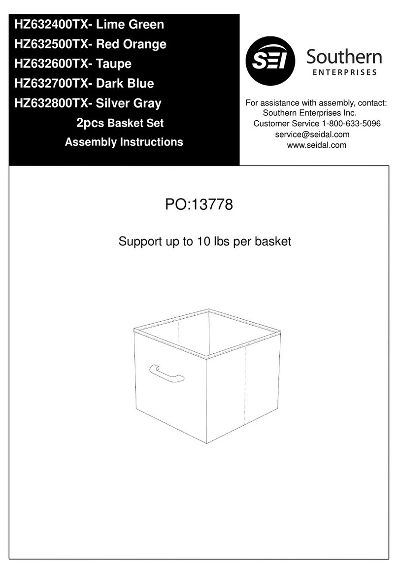
SEI WS605100TX User manual

SEI

SEI WS605100TX User manual

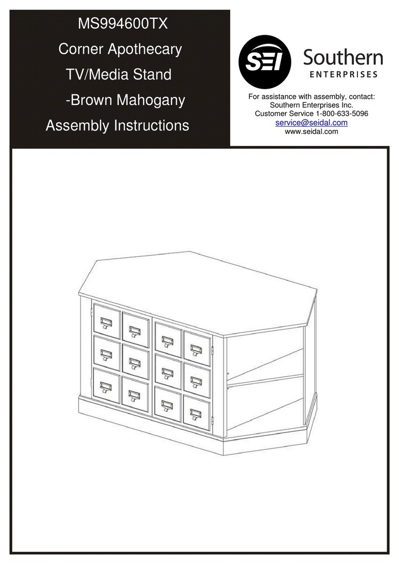
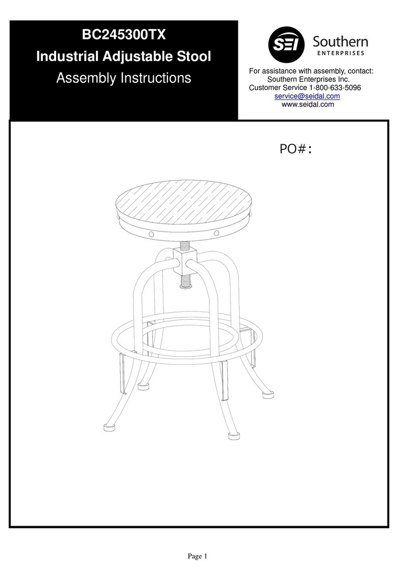
SEI MS994600TX User manual

SEI

SEI MS994600TX User manual

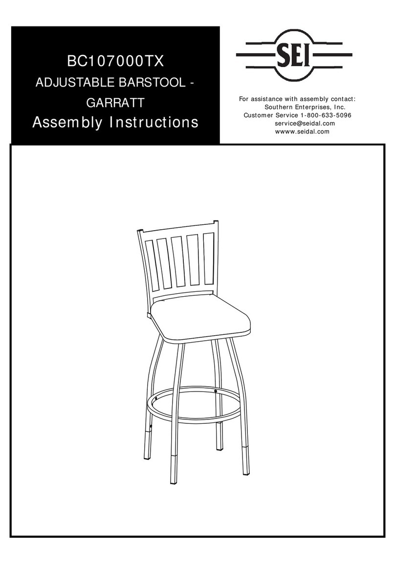
SEI Kismet Multi-Finish Cabinet HZ030300TX User manual

SEI

SEI Kismet Multi-Finish Cabinet HZ030300TX User manual

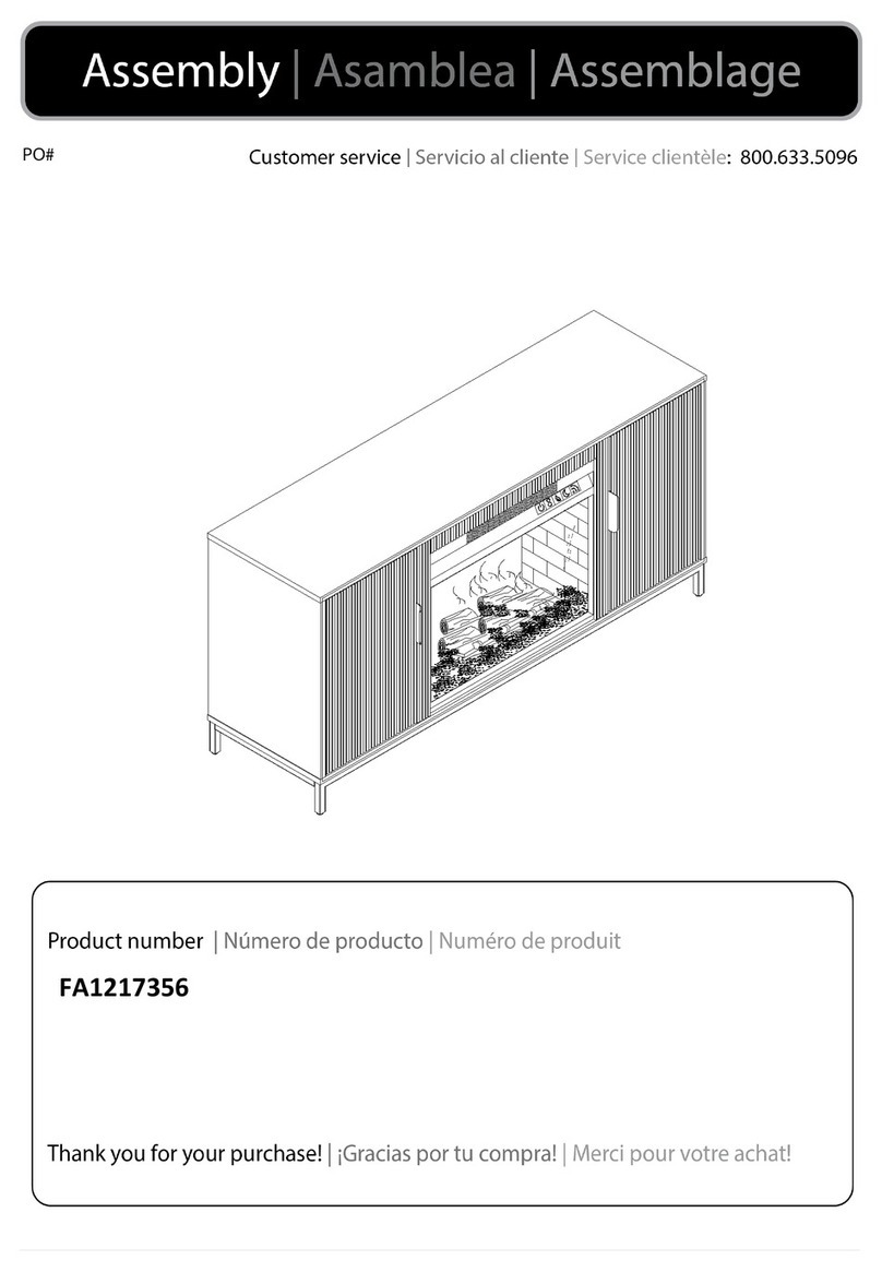
SEI Lucianna DN1490 User manual

SEI

SEI Lucianna DN1490 User manual

SEI HO872100TX User manual

SEI

SEI HO872100TX User manual

SEI CK1142600 User manual

SEI

SEI CK1142600 User manual

SEI Artisan BC946100TX User manual

SEI

SEI Artisan BC946100TX User manual

SEI HO1142737 User manual

SEI

SEI HO1142737 User manual

SEI Southern Enterprises HO979800TX User manual

SEI

SEI Southern Enterprises HO979800TX User manual

SEI FA1165456 User manual

SEI

SEI FA1165456 User manual

SEI MS089100TX-Berry Blue User manual

SEI

SEI MS089100TX-Berry Blue User manual

SEI CK886200TX User manual

SEI

SEI CK886200TX User manual

SEI HZ119700TX User manual

SEI

SEI HZ119700TX User manual

SEI CK222500TX User manual

SEI

SEI CK222500TX User manual

SEI HO664200TX User manual

SEI

SEI HO664200TX User manual

SEI OC341800TX User manual

SEI

SEI OC341800TX User manual

SEI BC4013 User manual

SEI

SEI BC4013 User manual

SEI HZ1167040 User manual

SEI

SEI HZ1167040 User manual

SEI HO731600TX User manual

SEI

SEI HO731600TX User manual

SEI HF0135 User manual

SEI

SEI HF0135 User manual

SEI CK7750 User manual

SEI

SEI CK7750 User manual

SEI Knox OC220400TX User manual

SEI

SEI Knox OC220400TX User manual

SEI WS706900TX User manual

SEI

SEI WS706900TX User manual

SEI HZ1216741 User manual

SEI

SEI HZ1216741 User manual

Popular Indoor Furnishing manuals by other brands

Regency LWMS3015 Assembly instructions

Regency

Regency LWMS3015 Assembly instructions

Furniture of America CM7751C Assembly instructions

Furniture of America

Furniture of America CM7751C Assembly instructions

Safavieh Furniture Estella CNS5731 manual

Safavieh Furniture

Safavieh Furniture Estella CNS5731 manual

PLACES OF STYLE Ovalfuss Assembly instruction

PLACES OF STYLE

PLACES OF STYLE Ovalfuss Assembly instruction

Trasman 1138 Bo1 Assembly manual

Trasman

Trasman 1138 Bo1 Assembly manual

Costway JV10856 manual

Costway

Costway JV10856 manual
moss DESIGN Caisson Credenza Assembly instructions

moss DESIGN

moss DESIGN Caisson Credenza Assembly instructions

Aquaglide FULL DECK 15.0 owner's manual

Aquaglide

Aquaglide FULL DECK 15.0 owner's manual

AREBOS AR-HE-SW30 user manual

AREBOS

AREBOS AR-HE-SW30 user manual

Till-Hilft Fulda 87005.330 Assembly instructions

Till-Hilft

Till-Hilft Fulda 87005.330 Assembly instructions

Twoey Outside 2010 quick start guide

Twoey Outside

Twoey Outside 2010 quick start guide

Hettich Easys 200 operating instructions

Hettich

Hettich Easys 200 operating instructions

The bedboss RELAX 404 Series owner's manual

The bedboss

The bedboss RELAX 404 Series owner's manual

Oeseder Möbelindustrie Bern 991 720 Assembly instructions

Oeseder Möbelindustrie

Oeseder Möbelindustrie Bern 991 720 Assembly instructions

Costway HW68469 user manual

Costway

Costway HW68469 user manual

Next ALIX A27743 Assembly instructions

Next

Next ALIX A27743 Assembly instructions

BROSA Hans Assembly guide

BROSA

BROSA Hans Assembly guide

Prodigg MINIKA PBA015T-FUR installation manual

Prodigg

Prodigg MINIKA PBA015T-FUR installation manual

manuals.online logo
manuals.online logoBrands
  • About & Mission
  • Contact us
  • Privacy Policy
  • Terms and Conditions

Copyright 2025 Manuals.Online. All Rights Reserved.

Page 1
HO610200TX
Wall Mount Desk
Assembly Instruction
For assistance with assembly contact:
Southern Enterprises Inc.
Customer Service 1-800-6 -5096
service@seidal.com
www.seidal.com
Page 2
1. Quantity
of 18
Wood Dowel 8* 0mm
2. Quantity
of 6
Cam Bolt
Wall Mount Desk
Parts List
Please check packaging for all parts and hardware before discarding. Unpack and lay parts on clean, padded
surface like carpet or blanket. Check that you have all parts indicated. Call customer service if hardware is
missing. Before beginning assembly, carefully study the diagrams below and sort your hardware according to the
pictures. Using the incorrect hardware will cause damage
A. Quantity
of 1
Top Panel l
B. Quantity
of 1
Side Panel(Left)
. Quantity
of 1
Side Panel(Right)
D. Quantity
of 1
Left Vertical Panel
E. Quantity
of 1
Right Vertical Panel
F. Quantity
of 1
Bottom Panel
G. Quantity
of 1
Back Panel
H. Quantity
of 2
Bottom Panel
I. Quantity
of 2
Rail
J. Quantity
of 2
Drawer Front Panel
K. Quantity
of 2
Drawer Side Panel(Left)
L. Quantity
of 2
Drawer Side Panel(Right)
M. Quantity
of 2
Drawer Bottom Panel
N. Quantity
of 1
Drawer Back Panel
O. Quantity
of 1
Keyboard
Page 3
3. Quantity
of 28
Cam Lock
4. Quantity
of 8
Cam Lock
5. Quantity
of 10
Screw 1/8”*1”L
6. Quantity
of 6
Plastic anchor
7. Quantity
of 4
Bolt
8. Quantity
of 2
Handle
9. Quantity
of 6
Screw 1/8” *1/2L
10. Quantity
of 4
Ball Bearing Slide
11. Quantity
of 2
Ball Bearing Slide
12. Quantity
of 6
Screw 1/8”*1-1/2L
13. Quantity
of 1
Level
14. Quantity
of 1
Slide
15. Quantity
of 8
cover
are and leaning Instructions:
Before using, wipe with a clean, dry cloth.
Periodically apply furniture wax to renew
the finish. Avoid rubbing or scratching the
surface with rough or abrasive objects.
all customer service at 1-800-633-5096
for assistance, questions, or Parts.
Assembly Tool Required No.2 Phillips
Screwdriver (Not Included)
Page 4
Wall Mount Desk
Assembly Instructions
Figure 1
Firstly please disassemble Metal
Slides(10) into Male Metal
Slide(10) and Female Metal
slide(10) as shown .
Figure 2
Firstly please disassemble Metal
Slides(11) into Male Metal
Slide(11) and Female Metal
Slide(11) as shown
Figure 3
Attach Female Ball Bearing Slides
(10/11) to Left Vertical Panel
(D)and Right Vertical Panel(E)
with Wood Screw (9).
Tighten screws with a phillips
screwdriver (not included)
Page 5
Figure 4
Attach Female Ball Bearing Slides
(10) to Left Side Panel (B) and
Right Side Panel(C)with
Wood Screw (9).
Tighten screws with a phillips
screwdriver (not included)
Figure 5
Insert Cam Lock ( ) into
predrilled holes on Middle
Bottom Panel (F).
Screw Cam Bolt (2) into
pre-drilled holes on Vertical Panel
(D/E).
Attach Vertical Panel (D/E ) to
Middle Bottom Panel(F) by
inserting Wood Dowel (1) & Cam
Bolt (2) into corresponding
pre-drilled holes until panels
meet.
Secure by rotating Cam Lock ( )
clockwise with a Philips
screwdriver.
Page 6
Figure 6
Insert Cam Lock ( ) into
predrilled holes on Side Bottom
Panel (H).
Screw Cam Bolt (2) into
pre-drilled holes on
pre-assembled unit from figure
5.
Attach Side Bottom Panel (H ) to
pre-assembled unit from figure 5
by inserting Wood Dowel (1) &
Cam Bolt (2) into corresponding
pre-drilled holes until panels
meet.
Secure by rotating Cam Lock ( )
clockwise with a Philips
screwdriver.
Figure 7
Insert Cam Lock ( ) into
predrilled holes on
pre-assembled unit from figure
6.
Screw Cam Bolt (2) into
pre-drilled holes on Back Panel
(G). Attach pre-assembled unit
from figure 6 to Back Panel(G)
by inserting Wood Dowel (1) &
Cam Bolt (2) into corresponding
pre-drilled holes until panels
meet.
Secure by rotating Cam Lock ( )
clockwise with a Philips
screwdriver.
Page 7
Figure 8
Attach Rail(I) to pre-assembled
unit from figure 7 with Wood
Dowel(1).
Figure 9
Insert Cam Lock ( ) into
predrilled holes on
pre-assembled unit from figure
8.
Screw Cam Bolt (2) into
pre-drilled holes on Side Panel
(B/C).
Attach Side Panel (B/C ) to
pre-assembled unit from figure 8
by inserting Wood Dowel (1) &
Cam Bolt (2) into corresponding
pre-drilled holes until panels
meet.
Secure by rotating Cam Lock ( )
clockwise with a Philips
screwdriver.
Page 8
Figure 10
Insert Cam Lock ( ) into
predrilled holes on
pre-assembled unit from figure
9.
Screw Cam Bolt (2) into
pre-drilled holes on Top Panel
(A). Attach Top Panel (A ) to
pre-assembled unit from figure 9
by inserting Wood Dowel (1) &
Cam Bolt (2) into corresponding
pre-drilled holes until panels
meet.
Secure by rotating Cam Lock ( )
clockwise with a Philips
screwdriver.
Figure 11
Screw Cam Bolt (2) into
pre-drilled holes on Drawer F
ront
Panel (J).
Page 9
Figure 12
Insert Cam Lock (4) into
predrilled holes on Drawer Side
Panel (K/L)
Attach Drawer Side Panel (K/L )
to Drawer Front Panel(J) by
inserting Cam Bolt (2) into
corresponding pre-drilled holes
until panels meet.
Secure by rotating Cam Lock (4)
clockwise with a Philips
screwdriver.
Insert the Drawer Bottom Panel
(R) into the corresponding
groove of Drawer front Panel (J)
& drawer side panel (K/L).
Attach the Drawer Back Panel (N)
to Drawer Side panel matching
the groove and tighten them by
using Screw (5).
Tighten screw with Phillips
screwdriver(not included)
Cover the cam lock hole with
cover(15).
Figure 13
Attach Male Ball Bearing Slide
(10) to Drawer with Screw (9)
Tighten screw with Phillips
screwdriver(not included)
Page 10
Figure 14
Attached Handle(8) to drawer
front with Bolt (7)
Tighten bolt with Phillips
screwdriver(not included)
Attached drawer box’s into figure
10 unit, please make sure drawer
box side’s male ball bearing slide
into side panel’s female ball
bearing slide, please try and
make sure ball bearing slide in
and out smoothly.
Figure 15
Attach Male Ball Bearing Slide
(11) to Keyboard(O)with Screw
(9)
Tighten screw with Phillips
screwdriver(not included)
Page 11
Figure 16
Attached keyboard into figure 14
unit, please make sure drawer
box side’s male ball bearing slide
into side panel’s female ball
bearing slide, please try and
make sure ball bearing slide in
and out smoothly.
Figure 17
Please mark a line on wall with
pencil as shown
Use a level on wall to insure line is
level
Figure 18
Place slide (14) against the wall at
the desired location.
then, mark each hole with a pencil.
Remove the slide.
Tip: If mounting to sheet rock (cavity
wall) it is advisable to mount at least
one screw (without anchor) directly to
a wall stud.
Page 12
Figure 19
Using a power drill and 3/16/” drill bit,
drill a hole through the wall at each
marked hole location where screw
(12) will not hit a stud in the wall.
Then insert plastic anchors (6) into
each hole and lightly tap anchors (6)
with a hammer until they are securely
flush with the face of the wall.
After the plastic anchors(C) are
securely in place, position slide (14)
to be mounted to the wall. Using a
philips screwdriver, drive in the
screws (12) into plastic anchors (C)
until the slide (14) is securely placed
on the wall.
Use a level on wall to insure slide(14)
is level
Figure 20
Place the pre-assembled unit
form figure 16 to slide as shown
Page 13
Figure 21
Use a level on table to insure table is
level
Figure
22
Now you wall mount desk is
ready for use
Max loading weight of top :20lbs
Max loading weight of
keyboard :10lbs
Max loading weight of each
drawer :10lbs
Page 14
Please immediately examine this product carefully. Any request for missing parts or damage replacement must be
received within 90 days of your receipt of the product. Replacement, if available, will be honored within this time
frame.Parts will not be available for items arriving fully assembled. We do not recommend mowe are not
responsible for any damages due to product modification(s).
If damages or missing parts are not reported within 90
days of your receipt, we are under no obligation to provide parts or replacement merchandise.
Please contact Southern Enterprises at 800-633-5096 or in Dallas 972-869-0111/ 9am – 4pm Mon-Fri Central time if
you have product issues or email us at service@seidal.com. Please ask for customer service representative for
issues involving damages or replacement parts. Please ask for technical assistance representative for any issues
with product and assembly/construction.
Please contact the retailer that you purchased from for returns.
Customer Information
Name
Address
City/State/Zip Code
Phone Number
Please indicate where you purchased this item: Store/Website/Catalog
Please indicate color/size/style number:
Style No Parts Letter Parts Description Quantity Needed
Customer Service 1-800-633-5096
service@seidal.com
Southern Enterprises, Inc.
600 Freeport Parkway, Suite 200
Coppell, Texas 75019
Parts Replacement Form