9
TECHNICAL GUIDE Cal. V14JA
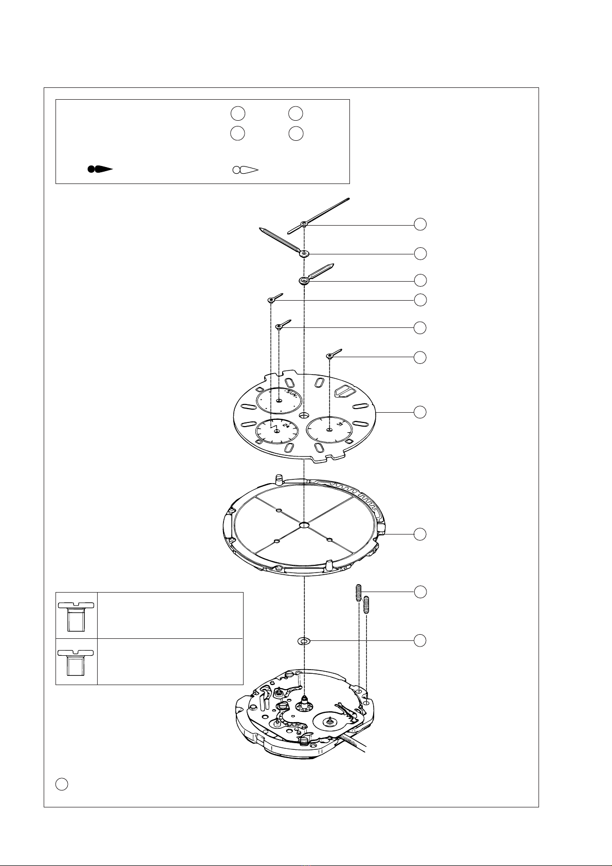
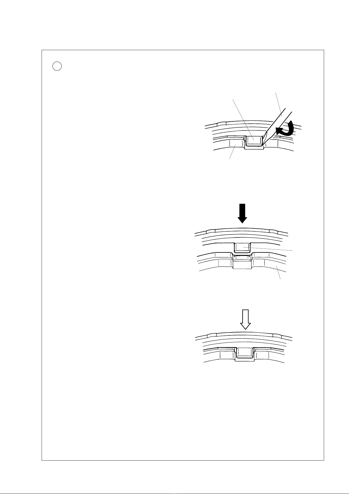
14 Date corrector setting wheel
•How to install
Set the date corrector setting wheel in the direction as
shown in the illustration at right, taking care not to set it
upside down.
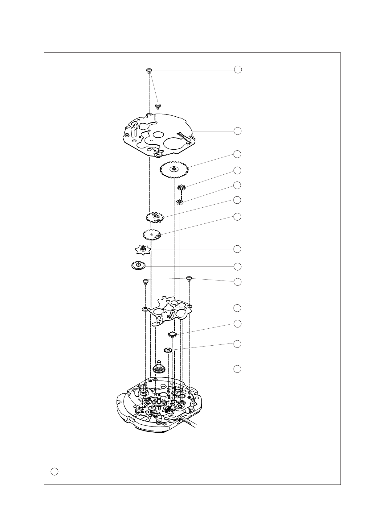
•How to install
Set the intermediate date wheel in the direction as shown
in the illustration at right, taking care not to set it upside
down.
15 Intermediate date wheel
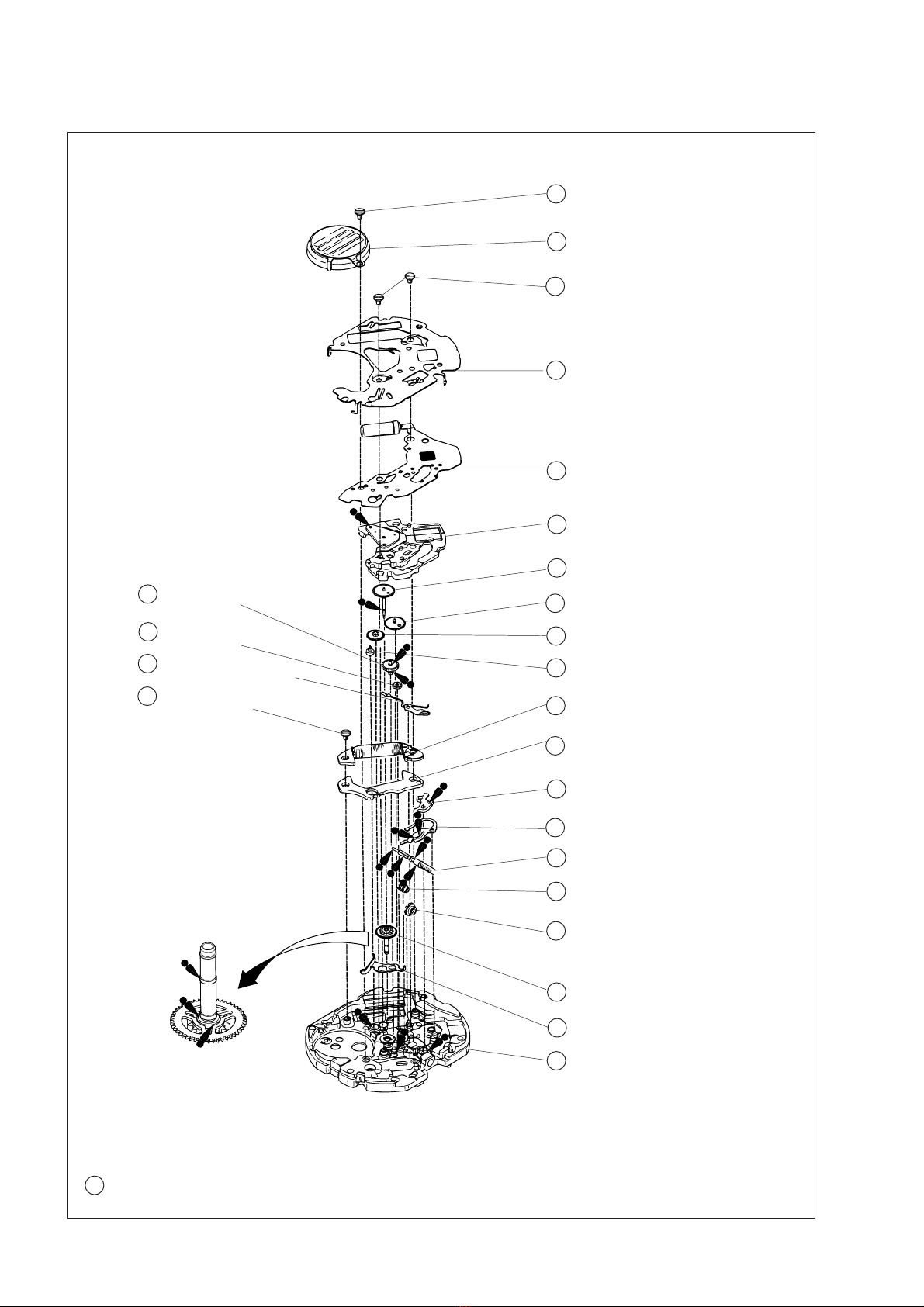
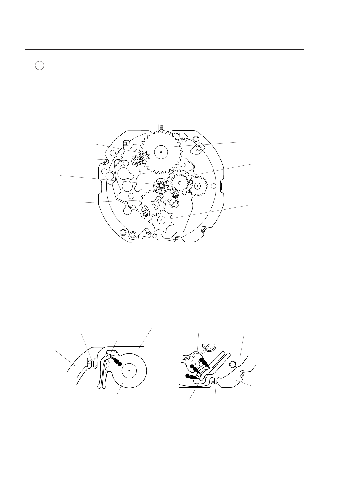
16 Day driving wheel
17 Date driving wheel
Cal. V14JA watches use two different driving wheels to
turn the date and day hands. It is necessary, therefore, to
adjust the engagement of the wheels so that the date and
day hands shift properly.
Top
Bottom
(Main plate side)
Bottom
(Main plate side)
Top
Day driving wheel
Date driving wheel
Guide post “A” of the main plate
Guide post “B” of the main plate
Guide post “A” of the main plate
Allowable range of installation Allowable range of installation
Guide post “B” of the main plate
Claw of the date driving wheel Claw of the day driving wheel
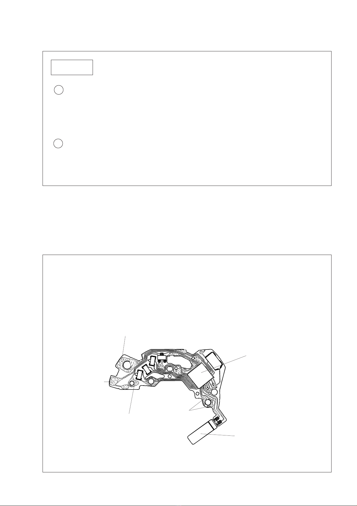
•How to install the date and day driving wheels for proper engagement
1) Install the date driving wheel so that its claw overlaps the guide post “A” of the main plate as shown in
the illustration below.
2) While checking that the date driving wheel does not move, install the day driving wheel so that its claw
overlaps the guide post “B” of the main plate as shown in the illustration below.