THREADING
THE
MACHINE (Fig. 7)
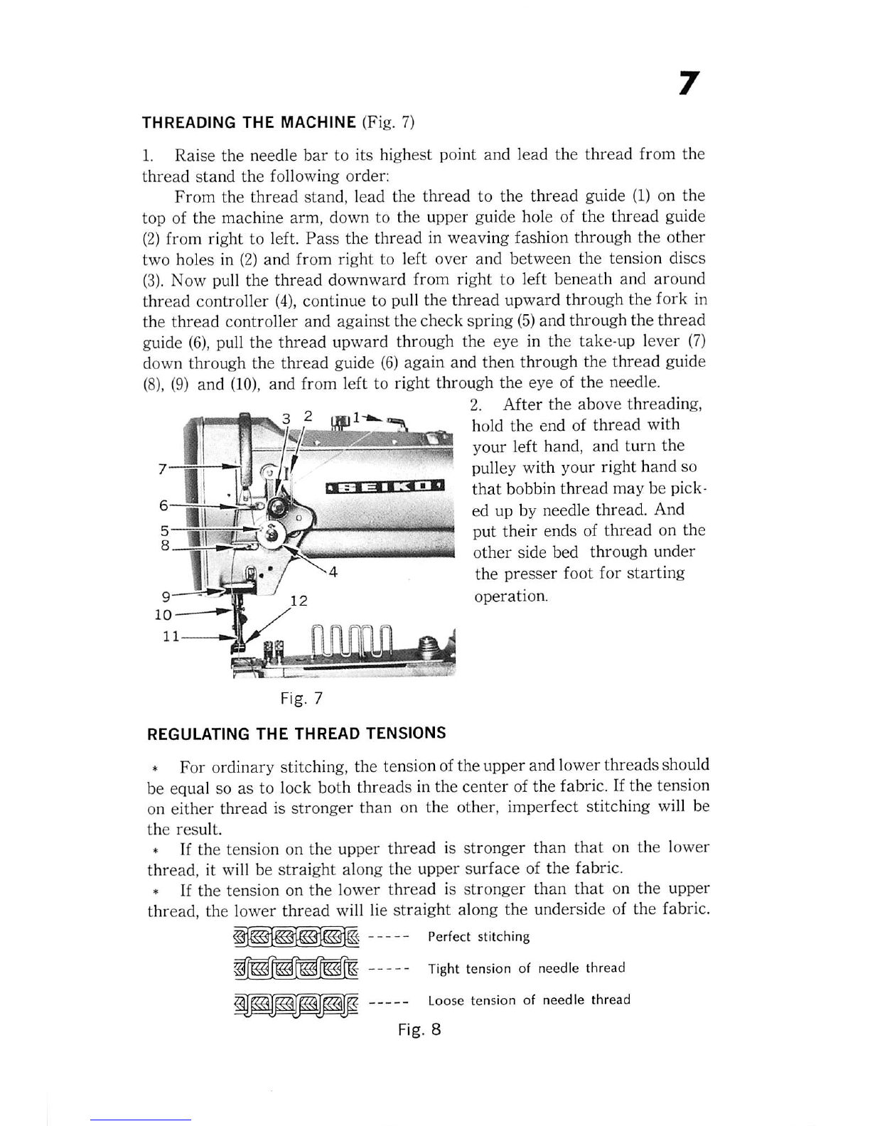
1. Raise the needle
bar
to
its
highest point
and
lead
the
thread
from
the
thread
stand
the
following
order:
From
the
thread
stand,
lead
the
thread
to
the
thread
guide (1) on
the
top of the machine arm, down to the upper guide hole of the thread guide
(2)
from right to left.
Pass
the
thread
in weaving fashion through the
other
two
holes in (2)
and
from
right
to
left
over
and
between
the
tension discs
(3).
Now pull the thread downward from right to left beneath and around
thread
controller
(4),
continue to pull the thread upward through the fork in
the
thread
controller
and
against
the
check
spring
(5)and
through
the
thread
guide
(6),
pull the thread upward through the eye in the take-up lever
(7)
down through the
thread
guide
(6)
again and then through the
thread
guide
(8),
(9) and
(10),
and from left to right through the eye of the needle.
2.
After
the
above
threading,
hold
the
end
of
thread
with
I t
your
left
hand,
and
turn
the
7—4—^1
pulley
with
your
right
hand
so
• '
.0
-1%
El
=•
=1
i ^
that
bobbin
thread
may
be
pick-
® ed up by
needle
thread.
And
put their ends of
thread
on the
®rii
i--
ifri'i
other
side
bed
through
under
1
iJ-JB**/
^
the
presser
foot
for
starting
9—12
operation.
DETQcrmii
Fig. 7
REGULATING
THE
THREAD
TENSIONS
* For ordinary stitching, the tension ofthe upper and lower threadsshould
be equal so as to lock both threads in the center of the fabric. If the tension
on either
thread
is stronger
than
on
the
other, imperfect stitching will be
the
result.
* If the tension on the upper
thread
is stronger
than
that
on the lower
thread, it will be
straight
along the upper surface of
the
fabric.
* If
the
tension
on
the
lower
thread
is
stronger
than
that
on
the
upper
thread, the lower
thread
will lie
straight
along the underside of
the
fabric.
Perfect
stitching
Tight tension of needle thread
Loose
tension
of
needle
thread
Fig. 8