Contents
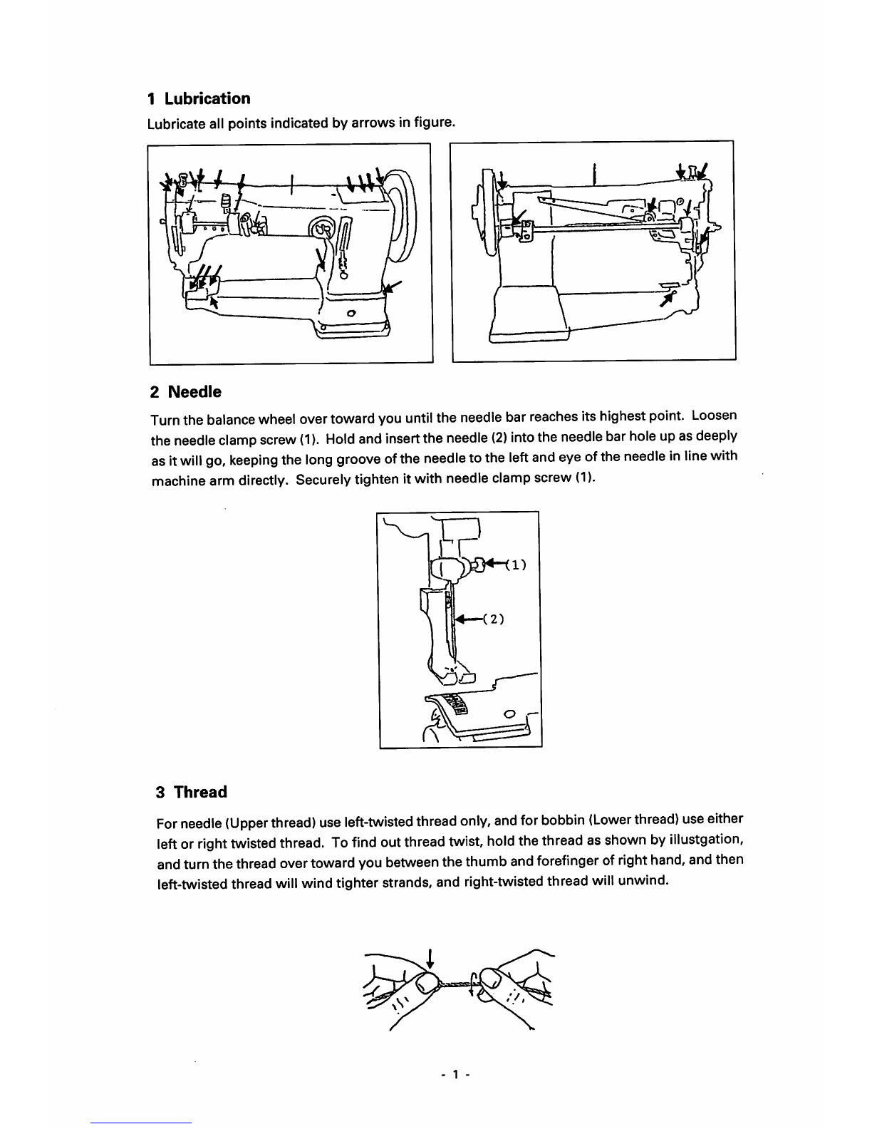
1Lubrication 1
2Needle 1
3Thread 1
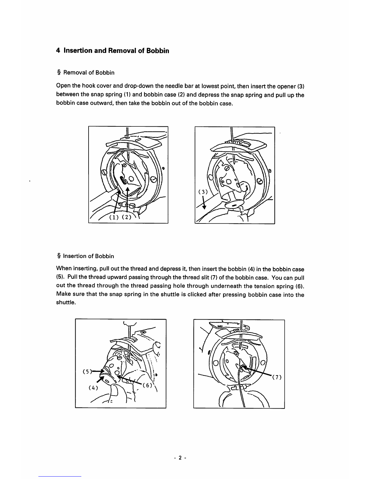
4Insertion
and
Removal 2
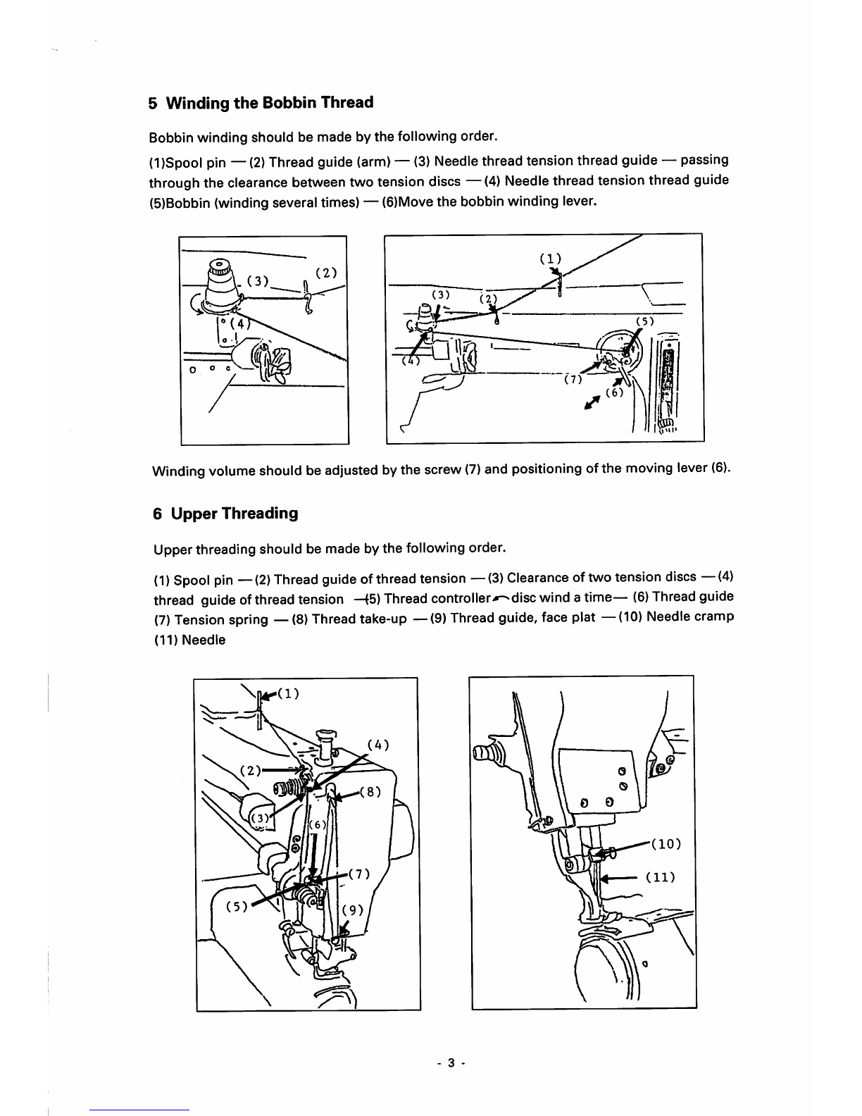
5 Winding the Bobbin Thread 3
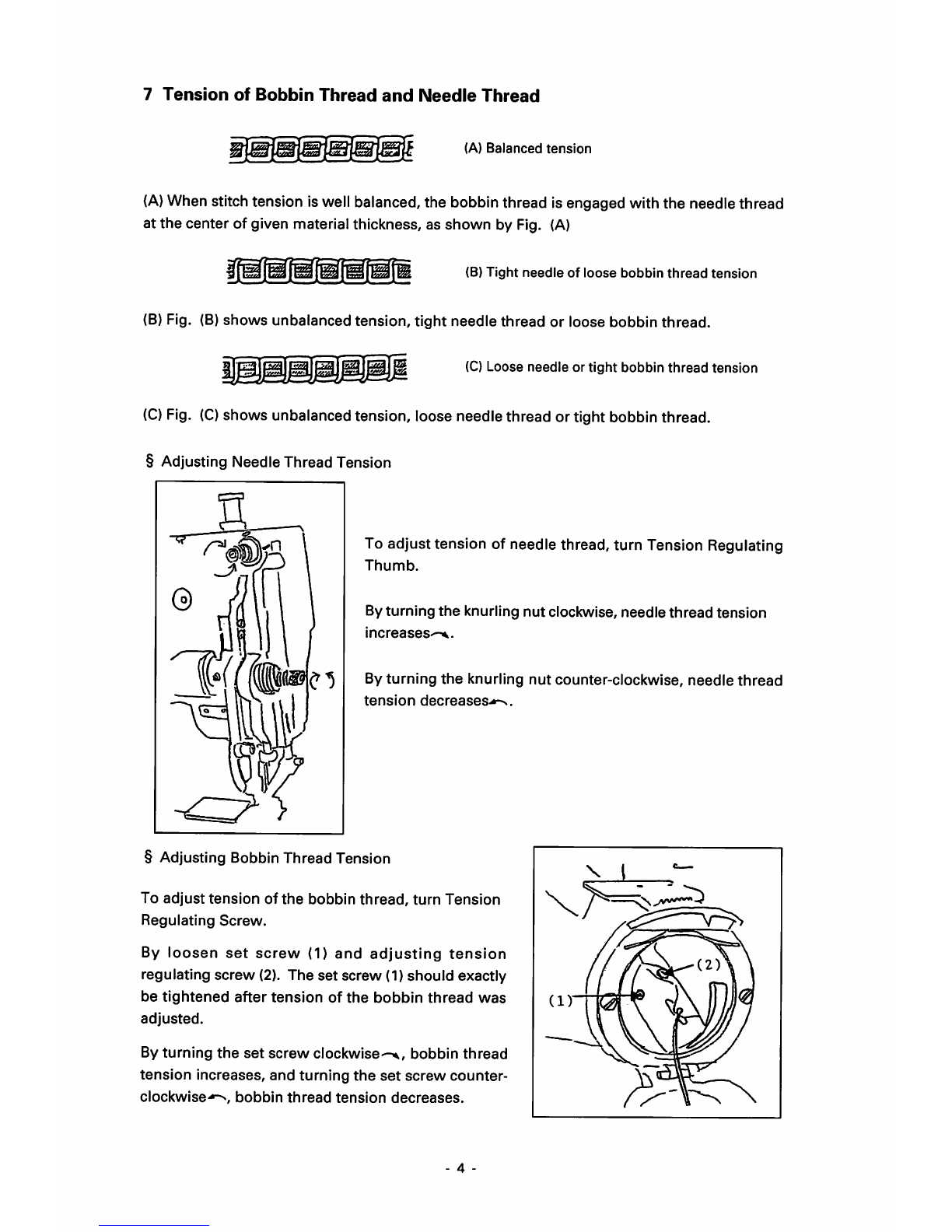
6Upper Threading 3
7Tension of Bobbin Thread and Needle Thread 4
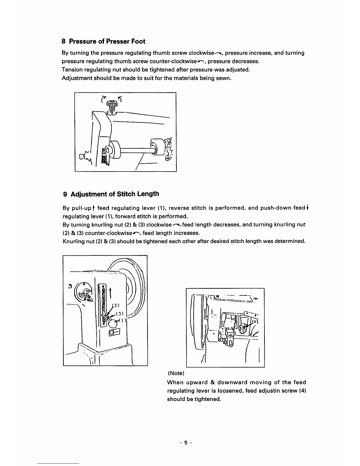
Adjusting Needle Thread Tension 4
Adjusting Bobbin Thread Tension 4
8Pressure of Presser Foot 5
9Adjustmentof Stitch Length 5
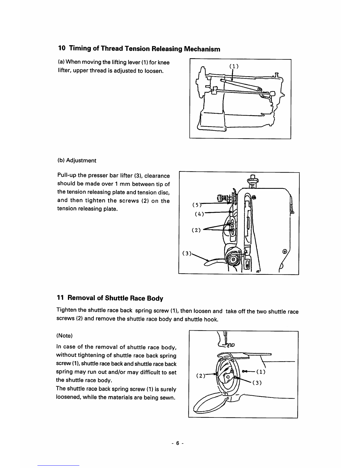
10 Timing of Thread Tension Releasing Mechanism 6
11
Removal of Shuttle Race Body 6
12 Adjusting on
the
Each Points 7
(A)
Adjusting Needle Position Against Needle Hole of 7
the
Feed
Dog
{7B & 8B
Types)
(B)
Adjusting of Feed Dog Height 7
(C)
Adjusting theForward and Backward Position of q
Needle
BarFrame
(D)
Timing of Needle and Hook 8
Positioning of
needle
and
tip of
the
hook 9
Adjusting
the
height of needle bar 9
Adjusting
the
position of
the
tip of hook 9
Clearance between needle
and
tip of hook 9
Each timing for up/down strokes of
presser
10
foot
(2B & SB
Types
only)
13
CH-2B/DF
11
a. Use of
the
Differential Feed Mechanism 10
b. Adjusting Upper Feed Length Against Lower Feed 11
Length
14
CH-2-DF
Adfusting
Upper
Feed
Length
11
Adfudting
Lower
Feed
Length 12
Positioning
Upper
Feed
Dog 13
Adjustment
14
Adjusting
Up/Down
Amount
of
Upper
Feed
14
Positioning
presser
Bar
15