Seiko 7T11A Quick start guide

Cal. 7T11A
[SPECIFICATIONS]
1/18
Movement
Item Cal. No. 7T11A
0 jewel
Stepping motor, 3 pieces
•Battery life indicator (The small second hand moves at two-second
intervals.)
•Second hand stop function
•Electronic circuit reset function
Monthly rate: Less than 15 seconds (worn on the wrist at
temperature range between 5 ºC and 35 ºC)
Use 10-second gate.
SEIKO SR927SW
Nil
1.55 V
Approx. 5 years
•STOPWATCH functions
Measure up to 12 hours in one second increments
Accumulated Elapsed Time Measurement
Split Time Measurement
STOPWATCH hand position adjustment
1 second
4002700, 2 pieces: 2.10 – 2.70 KΩ
1. Coil block for hour, minute, and small second
2. Coil block for stopwatch second
4002711, 1 piece: 1.80 – 2.40 KΩ
1. Coil block for stopwatch minute
Circuit block: Less than 0.20 µA
Movement: Less than 1.10 µA
Time setting, hand position adjustment / resetting the circuit
Free
Outside: Ø 27.6 mm Casing:Ø 27.0 mm
• Diameter
• Height: 3.3 mm
• 3 hands (hour, minute,
and small second hands)
•24 hour indicator
Battery No.
Driving system
Additional function
Crown operation
Loss/Gain
Regulation system
Gate time for rate measurement
Current consumption
Power supply
Battery life
Number of jewels
Interval of hands movements
Normal position
1st click position
Coil resistance
Battery voltage

SPECIFICATIONS
2/18
Cal. 7T11A has a new structure employing one crown and two buttons, but the basic movement
structure of Cal. 7T11A is similar to the previous Cal. 7T Series watches, and the knowledge and
technique you have gained in handling the previous Cal. 7T Series watches will come in handy
when you repair Cal. 7T11A.
When repairing, however, you are requested to have full knowledge of the features characteristic
of these watches and strictly observe the repairing and checking instructions provided in this
guide so that the watches will be repaired correctly.
FEATURES
Cal. 7T11A
●Measurement performance
Displays the elapsed time with the 3 designated STOPWATCH hands.
Measures up to 12 hours in one second increments.
●Button operation (Crown position: Normal position)
Button A: START/STOP
Button B: SPLIT/SPLIT RELEASE/RESET
1. STOPWATCH FUNCTION
Button B
Button A
Crown
Stopwatch second hand Minute hand
Stopwatch hour and minute hands
Hour hand
Small second hand
24-hour hand
Click position (Time setting
and adjusting the stopwatch
Normal position
hand position)
Cal. 7T11A
This is the multi-display analogue watch featuring a stopwatch function.
The time is indicated by the 24-hour, hour and minute hands, and a small second hand.
The stop watch can measure up to 12 hours.
After 12 hours, it will stop automatically.

SPECIFICATIONS
/18
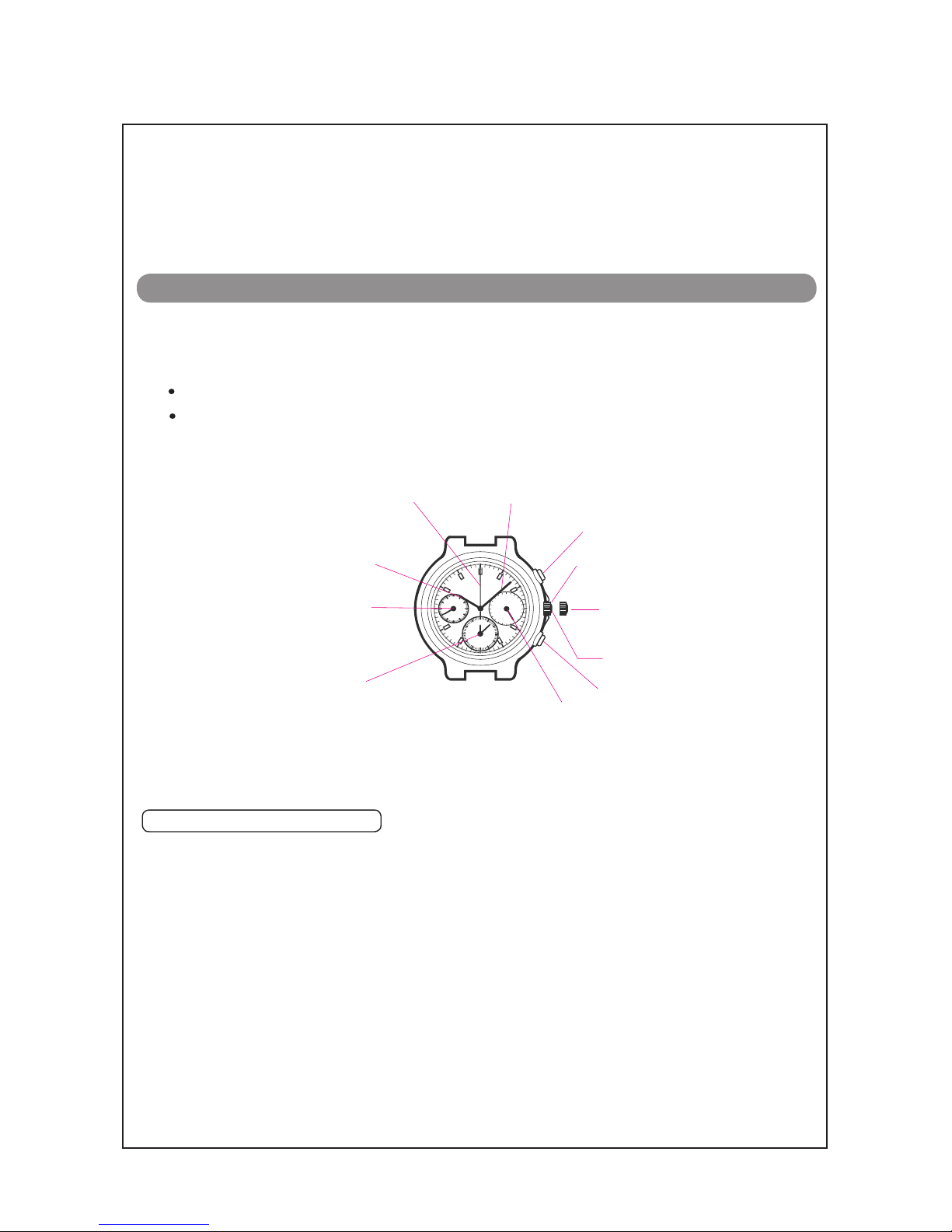
●Measurement functions
Accumulated elapsed time measurement and split time measurement are available.
Cal. 7T11A
●Standard measurement
Button A
START →Button A
STOP →Button B
RESET
●Split (intermediate) time measurement
Button A
START →Button B
SPLIT
Button B
SPLIT RELEASE
→ → → Button B
RESET
Button A
STOP
●Accumulated elapsed time measurement
Button A
START →Button A
STOP
Button A
STOP →Button B
RESET
→Button A
RESTART … →
Measurement and release of the split time can be repeated by pr essing button B.
Restart and stop of the stopwatch can be repeated by pressing b utton A.
●Measurement of two competitors
Button A
START
Button B
RESET
Button B
FINISH TIME OF FIRST
RUNNER
Button A
SECOND RUNNER
FINISH
→ →
Button B
FINISH TIME OF
SECOND RUNNER
→ →
After installing the battery, pull out the crown to the second click position. And then follow the
instructions below to correct the hand positions and set the time.
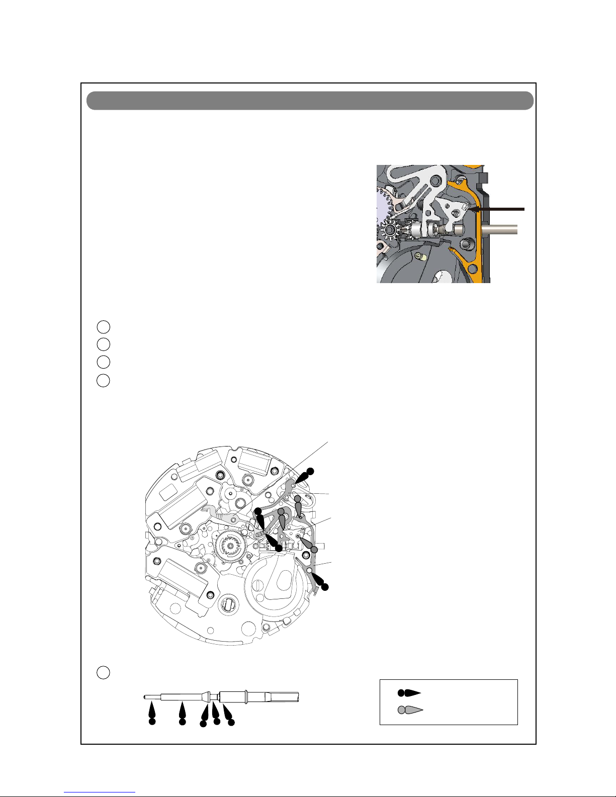
NECESSARY PROCEDURE AFTER BATTERY CHANGE
Pull out to the click position when the small second hand is at the
60 seconds position. The small second hand stops on the spot.
Turn to set the main time. * Check that AM/PM is correctly set.
Crown
Crown
Note*
Push back in to the normal position in accordance with a time signal.
Crown
Note* Pressing Button A for longer than 2 seconds here will allow you to resume the procedure again
Button A
Press Button A for longer than 2 seconds to ready for “0” position adjustment.
Button A
Press Button A for longer than 2 seconds.
The STOPWATCH second hand turns a full circle.
Button A
Press Button A for longer than 2 seconds.
The STOPWATCH hour and minute hand turns a full circle.
Button B
Press Button B to set the STOPWATCH second hand to the “0” position.
Button B
Press Button B repeatedly to reset the STOPWATCH
second hand to the “0”
if button B is kept pressed.
position. (12:00) It moves quickly
3

Cal. 7T11A
→
→
Disassembling procedures Figs.:
Reassembling procedures Figs.:
Remarks on removing the Setting stem
To remove the SETTING STEM when taking out
the movement from the case or while disassemb
-ling the parts during repair work, be sure to pull
out the crown to the first click, and then, remove
the SETTING STEM while pushing the setting
lever. Refer to page 9 for further details. 0027 973
4283 501
1002 501
0817 503
0271 583
0271 588
[24 HOUR INDICATOR
MECHANISM]
1PIN FOR 24HOUR WHEEL
PLATE
224 HOUR WHEEL PLATE
324 HOUR WHEEL
4
5
6
INTERMEDIATE WHEEL
FOR 24H WHEEL
HOUR WHEEL
HOUR COUNTING WHEEL
Lubricating of some parts is shown in “REMARKS ON DISASSEMBLING AND REASSEMBLING.”
4/18

Cal. 7T11A
0022 230
4225 530
0022 459
4457 814
0396 580
4000 564
4270 710
0125 577
0888 582
0241 583
0261 580
0950 590
0270 582
0261 582
0027 974
0240 580
0231 580
0701 580
0885 594
0885 595
0022 230
0022 459
7
8
9
10
11
12
13
14
15
16
17
18
19
20
21
22
23
24
25
26
27
BATTERY CLAMP SCREW
BATTERY CLAMP
BATTERY (SR927SW)
CIRCUIT BLOCK COVER SCREW
CIRCUIT BLOCK COVER
FRICTIOIN SPRING FOR
SECONDS COUNTING
CIRCUIT BLOCK
BATTERY CONNECTION (-)
TRAIN WHEEL BRIDGE
SECONDS COUNTING WHEEL
FOURTH WHEEL
MINUTE WHEEL
MINUTE COUNTING
INTERMEDIATE WHEEL
MINUTE COUNTING WHEEL
HOUR COUNTING
INTERMEDIATE WHEEL
PIN FOR TRAIN WHEEL BRIDGE
SMALL SECONDS WHEEL
THIRD WHEEL
FIFTH WHEEL
SECONDS COUNTING
1ST INTERMIDIATE WHEEL
SECONDS COUNTING
2ND INTERMIDIATE WHEEL
Lubricating of some parts is shown in “REMARKS ON DISASSEMBLING AND REASSEMBLING.”
BATTERY CLAMP SCREW
CIRCUIT BLOCK COVER
SCREW
[GEAR TRAIN MECHANISM]
5/18

Cal. 7T11A
4002 711
4002 700
4002 700
4146 710
4146 710
4450 703
0383 592
0384 582
0281 580
0351 583
4283 581
0221 583
0391 591
4146 710
0282 586
4239 710
4239 711 4239 712
4450 701
0100 588
28
29 COIL BLOCK
COIL BLOCK FOR
MINUTE COUNTING
COIL BLOCK FOR
SECONDS COUNTING
30
31
32
33 34
35
36
37
38
39
40
41
42
43
44 45
46
47
ROTOR FOR
MINUTE COUNTING
ROTOR FOR
SECONDS COUNTING SWITCH LEVER FOR START/
STOP BUTTON
SETTING LEVER
YOKE
SETTING WHEEL
SETTING STEM
ROTOR
CLUTCH WHEEL
SPACER FOR CENTER WHEEL
CENTER WHEEL
TRAIN WHEEL SETTING
LEVER
ROTOR STATOR
ROTOR STATOR FOR
SECONDS COUNTING
ROTOR STATOR FOR
MINUTE COUNTING
SWITCH LEVER FOR
RESET BUTTON
MAIN PLATE
Lubricating of some parts is shown in “REMARKS ON DISASSEMBLING AND REASSEMBLING.”
[SETTING MECHANISM/STEPPING MOTORS
(STATORS AND COIL BLOCKS)]
6/18

Cal. 7T11A
7/18
●How to find the correct parts, if not determined by 4 digit caliber number
Following parts are determined based on the design of watches, such as hands height, dial color,
and design of cases. Please refer to the SEIKO WATCH PARTS CATALOGUE in order to choose
corresponding parts.
* HOLDING RING FOR DIAL (0866788)
38
SETTING STEM (0351583)
●
How to discriminate resembled parts
Refer to the illustrations below to see the difference between those two types of pins.
1 PIN FOR 24HOUR WHEEL PLATE
0027973
18 PIN FOR TRAIN WHEEL BRIDGE
0027974
CAL. 7T62A
CAL. 7T11A, CAL.7T92A
CAL. 7T94A
No hole
Hole
Hole
CIRCUIT BLOCK
The circuit block (4000 564) for Cal.7T11A is also used for Cal.7T92A.
*The holes for discrimination are intended to discriminate
among the circuit blocks for Cal. 7T11A, 7T62A, 7T92A
and Cal.7T94.
*After Cal. 7T11A was launched, in order to commonize the
circuit block to Cal.7T92A, the shape of the circuit block was
changed. The old circuit block (4000 518) for Cal.7T92A is
usable only for Cal.7T92A. The new circuit block (4000 564)
is usable for both Cal.7T11A and Cal.7T92A.
13 (4000 564)

Cal. 7T11A
●Tools and consumables required for disassembling/reassembling
•Movement holder
UNIVERSAL MOVEMENT HOLDER
(S-682)
• Watch oils
SEIKO watch grease (S-6) and watch oils (AO-3 and AO-2)
S-6 AO-2
AO-3
8/18

TECHNICAL GUIDE Cal. 7T11A
REMARKS ON DISASSEMBLING AND REASSEMBLING
THE MOVEMENT
●How to remove the SETTING STEM before dismantling the movement
●Setting mechanism
•Setting position and lubricating
34 SWITCH LEVER FOR START/STOP BUTTON
35 SETTING LEVER
36 YOKE
42 TRAIN WHEEL SETTING LEVER
TRAIN WHEEL SETTING LEVER
YOKE
SETTING LEVER
SWITCH LEVER FOR START/STOP BUTTON
AO-3
SEIKO Watch Oil S-6
38 SETTING STEM
Crown position:
Click position
Push the SETTING LEVER gently (refer to the picture on the
right) in order to disengage it from the SETTING STEM. Then
pull out the crown with the stem completely.
9/18

Cal. 7T11A
TECHNICAL GUIDE
15 TRAIN WHEEL BRIDGE and 18 PIN FOR TRAIN WHEEL BRIDGE
●Gear train mechanism
After setting the as illustrated
below, lubricate the upper pivots of the following parts:
•32 ROTOR, 33 ROTOR FOR SECONDS COUNTING,
COUNTING (as illustrated below)
•24 MINUTE WHEEL, 16 SECONDS COUNTING WHEEL
Upper pivot of the ROTOR
Upper pivot of the MINUTE WHEEL Other portions
WHEEL (as illustrated below)
31 ROTOR FOR MINUTE
and 19 SMALL SECONDS
16 SECONDS COUNTING WHEEL
41
CENTER WHEEL
10/18

Cal. 7T11A
TECHNICAL GUIDE
Setting position and lubricating
●Gear train mechanism
MINUTE COUNTING
WHEEL
0270 582
26
0950 590
25 MINUTE COUNTING
INTERMEDIATE WHEEL
(white plastic)
0231 580
20 THIRD WHEEL
0241 583
17 FOURTH WHEEL
0261 582
27 HOUR COUNTING
INTERMEDIATE
WHEEL (white plastic)
0888 582
16 SECONDS COUNTING
WHEEL
0240 580
19 SMALL SECONDS
WHEEL
0701 580
21 FIFTH WHEEL
(Green plastic)
0885 594
22 SECOND COUNTING
1ST INTERMIDIATE
WHEEL (Green plastic)
0885 595
23 SECONDS COUNTING
2ND INTERMIDIATE
WHEEL (white plastic)
0261 580
24 MINUTE WHEEL
(white plastic)
4283 581
40
SPACER FOR
CENTER WHEEL
4146 710
32 ROTOR
4146 710
31 ROTOR FOR
MINUTE COUNTING
4146 710
ROTOR FOR SECONDS
COUNTING
11/18

Cal. 7T11A
TECHNICAL GUIDE
47
MAIN PLATE
Lubricating
12/18

TECHNICAL GUIDE Cal. 7T11A
13/18
REMARKS ON INSPECTION AND MEASUREMENT
1. To measure the current consumption for the whole move -
ment, connect the (-) probe to the battery connection (-)
and (+) probe to the other metal part of the movement,
such as battery clamp or circuit block cover.
* When measuring the current consumption using the
SEIKO digital multi-tester (S-860), use the range of 40 µ
A of SUPPLY V (= 1.55 V) & GATE TIME (2 S).
2. Connect the AC component to the positive terminal for 2
seconds until a short circuit occurs to reset the integrated
circuit.
3. After the integrated circuit is reset, wait approximately for
10 seconds until a stable measurement is obtained, and
then read the measurement.
4. Make sure the read value is less than 1.10 µ A.
●How to measure the current consumption for the whole movement
●How to measure the current consumption for the CIRCUIT BLOCK alone
1. To measure the current consumption for the CIRCUIT
BLOCK alone, connect each probe to the appropriate
positive (+) or negative (- ) input terminal of the CIR -
CUIT BLOCK (please refer to “Structure of the CIRCUIT
BLOCK” below).
*When measuring the current consumption using the
-
SEIKO Multi-Tester S-860, use the range of 4 µ A of SUPPLY
V (= 1.55 V) & GATE TIME (2 S).
2. Repeat the same procedures as 2. and 3. of measuring
current consumption for the whole movement above.
*When measuring the current consumption for the CIRCUIT
BLOCK alone, be careful not to damage or deform the pat
tern of the circuit block.
3. Make sure the read value is less than 0.20 µ A.

TECHNICAL GUIDE Cal. 7T11A
14/18
●Value checking – coil resistance (coil blocks)
Check the resistance of each coil block if they are within the range in the following table.
2.10 K Ω ~ 2.70 KΩ
1.80 KΩ ~ 2.40 KΩ
COIL BLOCK
COIL BLOCK FOR SECONDS COUNTING
COIL BLOCK FOR MINUTE COUNTING
4002700
4002700
4002711
2.10 KΩ ~ 2.70 KΩ
C-MOS-IC
[Structure of the CIRCUIT BLOCK]
Input terminal (+)
Output terminal
Output terminal
Crystal unit
Input terminal (-)
Output terminal

TECHNICAL GUIDE Cal. 7T11A
15/18
●Function check
Before doing the following function check, follow the instructions on P.3 to correct the hand
positions, set the time and operate the stopwatch function.
Operation Function Check point
Pull out the crown to
the click position and
push it back in to the
no rma l p os ition. Rep ea t
the same several times.
Setting mechanism
- switching the function
of the time seting
Make sure that it has a
click at the position
and th e s t e m i s n o t
pulled off.
Pull out the crown to
the click position when
the small second hand
stops on the spot.
Stop watch second
hand stop function
Make sure that the stop
watch second hand
stops when the crown
is pulled out to the click
position.
Setting mechanism
- hour and minute
hand setting
M a k e s u r e t h a t t h e
hour and minute hands
move smoothly (without
t o u c h i n g e a c h other
or touching the surface
of the dial or inside of
the glass).
Hands installation
A
B
<Standard Measurement>
Press button A to stop the
stopwatch.
Press button B to reset the
stopwatch.
A A B
Start Stop Reset
Stopwatch mecha -
nism
<Split Time Measurement>
A B B A B
Start Split Split Stop Reset
Release
M a k e s u r e t h a t t h e
Stopwatch hands start/
stop smoothly.
M a k e s u r e t h a t t h e
Stopwatch hands are
reset to the “0” posi -
tion.

TECHNICAL GUIDE Cal. 7T11A
16/18
●
Water resistance test
●
Accuracy test
Check the water resistance according to the designated specification of the watch.
Measure the rate and make sure the value shows within ±0.50 s/d.
Use 10 seconds gate of the tester.
Water resistance test
WATER RESIST 5 BAR
WATER RESIST 10 BAR
WATER RESIST 15 BAR
WATER RESIST 20 BAR
WATER RESISTANT (WATER RESIST)
Marking on the case back
Air overpressure test
Wa t e r ov e r pr e s sur e
test and condensation
test
Wate r-tigh tne s s an d
w a t er ov er p r e s s u r e
test and condensation
tests before/after water
overpressure test
SCUBA DIVER’S (AIR DIVER’S) 150 m
SCUBA DIVER’S (AIR DIVER’S) 200 m
He-GAS DIVER’S 300 m
He-GAS DIVER’S 600 m
He-GAS DIVER’S 1000 m
18.75 BAR = 150 (m) times 0.125
25 BAR = 200 (m) times 0.125
37.5 BAR = 300 (m) times 0.125
75 BAR =600(m)times 0.125
125 BAR = 1000 (m) times 0.125
3 BAR
5 BAR
10 BAR
15 BAR
20 BAR
Applied pressure

TECHNICAL GUIDE Cal. 7T11A
17/18
Movement
TROUBLESHOOTING
The watch stops operat -
ing.
The battery has been depleted. Measure the batter y voltage.
Replace the battery with a new
one.
The hour wheel and the pinion of
the minute wheel are not prop -
erly engaged. (Or the teeth of the
hour wheel and/or minute wheel
have been broken.)
Check the relevant par ts, and
replace the damaged parts with
new ones.
The hooking portions of the cir -
cuit block cover are not properly
engaged, resulting in poor con -
ductivity.
Securely attach the hooks of the
circuit block cover to the main
plate.
The coil is broken.
Measure the coil block resis t -
ance. Replace the coil with a new
one.
One or more wheels have been
contaminated with dirt, dust or
other particles.
An excessive amount of oil in the
movement has caused adhesive
forces among the parts. (wring -
ing)
Remove dirt or dust and clean the
contaminated wheels. Be careful
so as not to damage the teeth of
the plastic parts while cleaning.
The current consumption
for the whole movement
e x c e e d s t h e s t a n d a r d
value.
Dirt, dust or foreign particles are
adhered to the movement.
Remove dirt, dust or foreign par -
ticles and clean the movement.
The driving pulse is generated in
order to compensate the exces -
sive load applied to the wheels.
(The oil has deteriorated, leaked
or run out.)
If the current consumption for
the circuit block alone is within
the standard value range, over -
haul and clean the movement
parts, and then make the meas -
urement again.
The current consumption
for the circuit block alone
exceeds the standard val -
ue.
The light from outside the move -
ment is af fecting the measure -
ment.
Shut out the light, and make the
measurement again.
There is a defect in the IC (inte -
grated circuit).
Replace the circuit block with a
new one.
Symptom Possible causes Solutions

TECHNICAL GUIDE Cal. 7T11A
18/18 Copyright©2009 by
STOPWATCH
O n e o r m o r e S T O P WATCH
h a n d s h a v e stopped
moving or show an
abnormal movement.
The relevant coil is broken. Measure the coil block resis t -
ance. Replace the coil with a new
one if necessary.
An excessive load is being ap -
plied to the chronograph wheels
due to dust or foreign particles
adhering to them or oil starva -
tion.
Clean the relevant parts and lu -
bricate with an adequate amount
of oil.
The step motor shows an
abnormal movement
.
There is a crack on the circuit
block switch pattern.
Replace the circuit block with a
new one.
The buttons do not oper -
ate normally.
The amount of oil around the but -
tons is insufficient.
Clean the buttons and lubricate
appropriately.
The circui t blo ck pa t tern ha s
been broken or bent.
Adjust the circuit block pattern
or replace the circuit block with a
new one.
The crown falls off. The winding stem is not securely
installed. (the setting lever and
yoke are disengaged.)
Check the main plate, winding
stem, set ting lever and yoke.
Replace the defective parts with
new ones.
The current consumption
exceeds the standard value.
An excessive load is being ap -
plied due to friction among the
hour, minute and STOPWATCH
hands.
Small amount of water/
blur inside of the glass
persists.
Water resistance is deteriorated.
The watch has been subjected to
water pressure that exceeds the
guaranteed degree.
Investigate the causes to take
necessary measures, while clean -
ing inside of the watch.
Replace the s tator with a new
one.
Adjust or remount the relevant
hands.
Symptom Possible causes Solutions
Exterior
parts
The step motor has b een d e -
formed.
Seiko Watch Corporation
Table of contents
Other Seiko Watch manuals

Seiko
Seiko CREDOR 7R06 User manual

Seiko
Seiko Pulsar Y182 User manual

Seiko
Seiko Cal. S058 User manual

Seiko
Seiko quartz M354 User manual

Seiko
Seiko Cal. V198 User manual

Seiko
Seiko Cal. 5M82 User manual

Seiko
Seiko Grand 3F81 User manual

Seiko
Seiko 4M21 User manual

Seiko
Seiko Astron 7X52 Instruction manual

Seiko
Seiko Grand Seiko SPRING DRIVE DIVERS 9R65 User manual

Seiko
Seiko V147 User manual

Seiko
Seiko Conceptual SUR377P User manual

Seiko
Seiko Grand Seiko 9S65 User manual

Seiko
Seiko YT57B Quick start guide

Seiko
Seiko Cal. 5M83 User manual

Seiko
Seiko Cal. 9R84 User manual

Seiko
Seiko Presage SRPB41J User manual

Seiko
Seiko 5M84A User manual

Seiko
Seiko 4205B Quick start guide

Seiko
Seiko 9R86 User manual