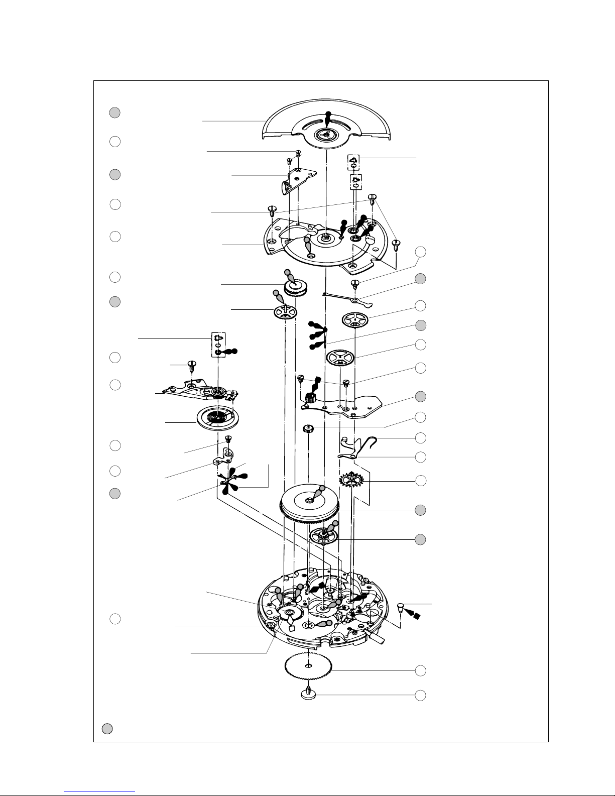
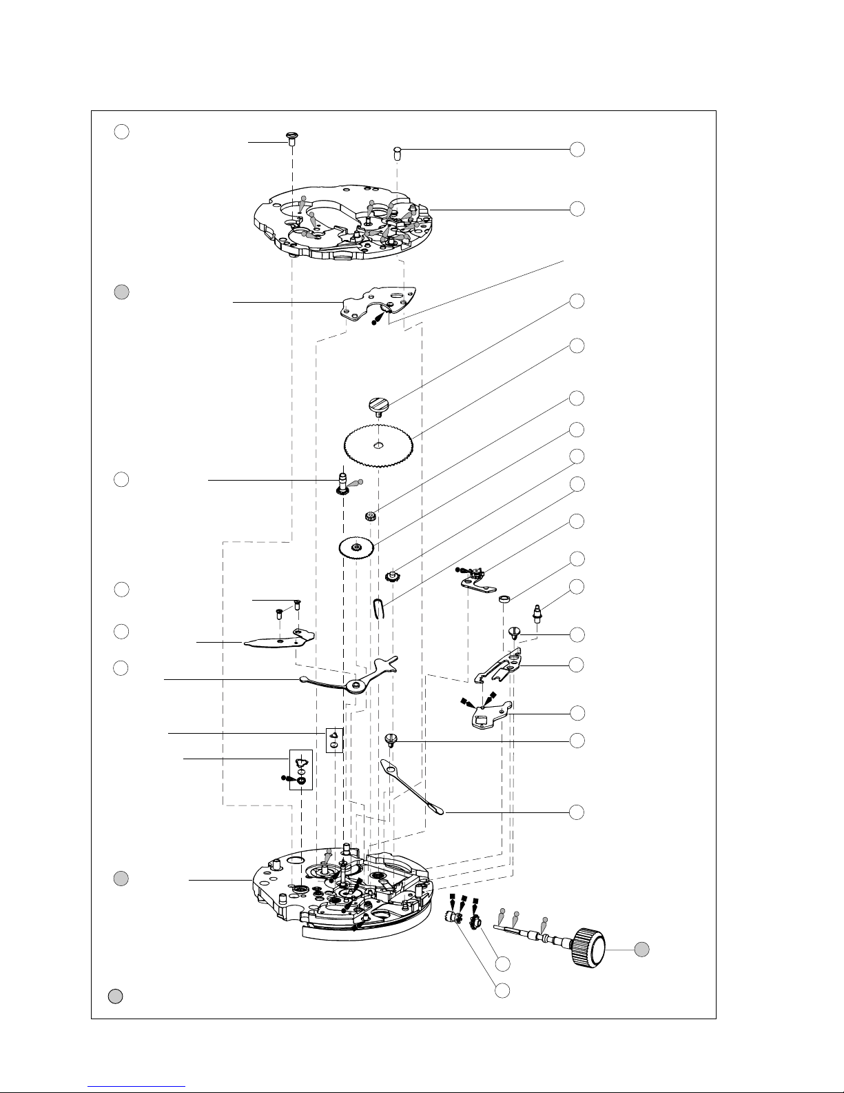
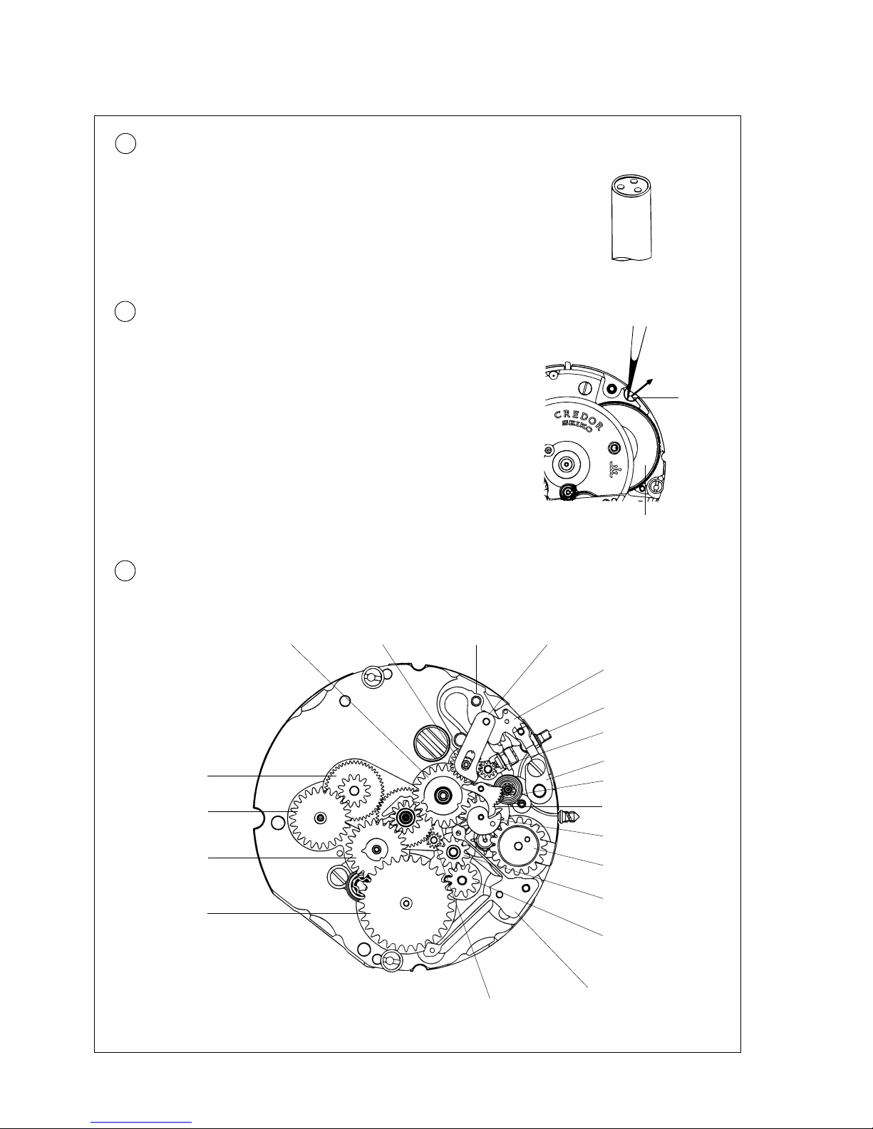
Seiko 4S77A Installer manual

1
PARTS CATALOGUE/TECHNICALGUIDE
[SPECIFICATIONS]
Movement
Item
Cal. No.
Brand CREDOR
4S77A
Cal. 4S77A
Movement size
(x 1.0)
Casing diameter
Outside diameter
Height
ø26.0 mm
ø25.6 mm
5.38 mm
Time indication Three hands (Hour, minute and second hands)
with 24-hour, date and day hands
Vibrations per hour 28,800 (8 beats per second)
Additional mechanism •Automatic winding (with auxiliary hand winding mechanism)
•Calendar indicated by hands (Date and day of the week)
•Instant setting device for date and day calendar
•24-hour hand
•Independent adjustment of hour hand
•Micro-regulating device
•Second setting device
•Regulating device by micro-positioning regulator pin
Loss/gain Daily rate at normal temperature range: Within a range between
+15 seconds and -10 seconds
Jewels 28 jewels

2
PARTS CATALOGUE
Disassembling procedures Figs. : 1 ~ 80
Reassembling procedures Figs. : 80 ~ 1
Lubricating: Types of oil Oil quantity
Liberal quantity
Normal quantity
Extremely small
➡➡Please see the remarks on the following pages.
Cal. 4S77A
Moebius V
Moebius A
SEIKO Watch Oil S-6
SEIKO Watch Oil S-4
SEIKO Watch Oil S-3
1 Hour, minute and
second hands
2 Date hand
1 24-hour hand
2 Day hand
10 0012 354
Auxiliary train wheel
bridge screw
11 0126 116
Auxiliary train
wheel bridge
4 Dial
12 0165 002
Small hour hand
corrector lever
18 0817 035
Intermediate small hour hand
corrector wheel and pinion
19 0281 077
Small hour hand
corrector setting wheel
20 0898 001
Day indicator driving wheel
21 0165 002
Small hour hand wheel
23 0817 036
Intermediate small hour
hand hand wheel and pinion
24 0802 029
Date driving wheel
25 0810 003
Date jumper
26 0981 008
Date star
29 0012 354
Setting lever spring screw
30 0388 021
Setting lever spring
31 0383 176
Small hour hand corrector
setting lever
32 0384 890
Small hour hand corrector yoke
13 0585 014
Hammer
14 1019 077
Day wheel
15 0817 029
Intermediate day driving wheel
16 0989 027
Intermediate wheel for
day corrector B
17 0989 026
Intermediate wheel
for day corrector A
27 0804 001
Intermediate date corrector
setting wheel A
28 0804 002
Intermediate date corrector
setting wheel B
34 Small hour hand corrector
winding stem
33 0282 077
Small hour hand corrector
clutch wheel
22 Hour wheel

3
➡➡Please see the remarks on the following pages.
5 0509 108
Oscillating weight with
ball bearing
6 0012 744
Screw for framework for
automatic device (2 pcs.)
PARTS CATALOGUE Cal. 4S77A
7 Framework for automatic device
3 0013 975
(Dial leg pin)*
0429 001
(Support for second reduction
wheel and pinion)
0514 003
(Second reduction wheel
and pinion)*
* The dial leg pin and second reduction wheel
and pinion cannot be disassembled as they
are fixed to the main plate.
Diashock
51 0012 284
Balance cock
screw
43 0012 513
Rachet wheel screw
(left-hand thread)
44 0285 023
Rachet wheel
69 0251 018
Escape wheel and pinion
66 0851 002
Second reverser idler
64 0012 285
Center wheel bridge screw
(2 pcs.)
61 Second wheel pinion
59 0012 673
Screw for friction spring for
second wheel pinion
Diafix
70 Center wheel and pinion
with cannon pinion
63 0201 275
Complete barrel with mainspring
65 0122 030
Center wheel bridge
57 0112 284
Barrel and train wheel bridge
56 0012 284
Screw for barrel and train
wheel bridge (3 pcs.)
8 0531 003
Differential wheel and pinion
9 0511 004
First reduction wheel and pinion
52 0171 076
Balance
cock
0310 034
Balance complete
with stud
53 0012 285
Pallet cock screw
54 0161 030
Pallet cock
55 0301 012
Jewelled pallet
fork and staff
Moebius A
0390 005
Setting lever axle
68 0391 006
Train wheel setting lever
67 0361 002
Train wheel setting lever spring
62 0231 012
Third wheel and pinion
58 0241 016
Fourth wheel and pinion
60 0396 003
Friction spring for second
wheel pinion

4
➡➡Please see the remarks on the following pages.
PARTS CATALOGUE Cal. 4S77A
36 0012 820
Auxiliary plate screw (A)
35 0012 201
Auxiliary plate screw (B)
37 0102 117
Auxiliary plate
38 0387 007
Minute wheel bridge
39 Cannon pinion
46 0012 820
Date jumper guard screw
47 0809 001
Date jumper
73 0384 023
Yoke
Diafix
Diashock
80 Main plate
77 Winding
stem
76 0381 010
Click
75 0012 672
Click screw
74 0383 024
Setting lever
72 0388 006
Setting lever spring
78 0283 006
Winding pinion
79 0282 031
Clutch wheel
71 0012 354
Setting lever spring screw
50 0390 116
Setting lever axle
(for small hour hand
corrector)
49 4408 189
Auxiliary plate spacer
48 0981 008
Day/date corrector wheel
rocker
45 0363 003
Sliding crown wheel
spring
42 0286 003
Sliding crown wheel
41 0261 009
Minute wheel and pinion
40 0281 076
Setting wheel
44 0285 023
Rachet wheel
43 0012 513
Rachet wheel screw
(left-hand thread)
(Crown wheel)

5
PARTS CATALOGUE
•List of screws
• Stud screw • Click screw
0012 121 0012 672
0012 284 0012 673
0012 285
• Yoke holder screw
• Auxiliary train wheel
bridge screw
• Setting lever spring
screw
0012 726
0012 354
• Rachet wheel screw
0012 744
0012 513
• Auxiliary plate screw (A)
• Date jumper guard
screw
0012 201
0012 820
NamePart No.NamePart No.
Cal. 4S77A
• Casing clamp screw
• Screw for barrel and train
wheel bridge
• Balance cock screw
• Screw for friction spring
for second wheel pinion
• Center wheel bridge
screw
• Pallet cock screw
• Auxiliary plate screw (B)
• Screw for framework for
automatic device

6
PARTS CATALOGUE Cal. 4S77A
•List of jewels
0011 540
• Lower hole jewel for fourth wheel
and pinion
0011 505
0011 541
0011 151
0011 422
0011 157
•List of tubes and pins
0032 165
Part No. Name Part No. Name
• Diashock upper/lower cap jewel
• Diafix upper cap jewel for fourth
wheel and pinion
• Diafix upper/lower cap jewel for
escape wheel and pinion
0011 221 • Upper/lower hole jewel for third
wheel and pinion
• Upper hole jewel for complete
barrel with mainspring
0011 398
• Upper hole jewel for center wheel
and pinion
0011 715
• Lower hole jewel for center wheel
and pinion
0011 146
0013 934 • Micro adjuster pin
• Dial leg pin
0013 975
• Upper/lower hole jewel for jewelled
pallet fork and staff
• Upper/lower hole jewel for first
reduction wheel and pinion
• Upper hole jewel for differential
wheel and pinion
• Lower hole jewel for differential
wheel and pinion
0013 481 • Pin for second reduction wheel
and pinion
0032 166 • Tube for auxiliary train wheel bridge
• Tube for balance cock (B)
0344 080
Part No. Part No. NameName
•Other parts
• Regulator pointer
0345 010 • Stud holder
0468 003 • Lower hole jewel with frame for
jewelled pallet fork and staff
0014 603 • Diashock upper frame
0341 016 • Regulator
0014 605 • Diashock upper/lower hole jewel
with frame
0014 317 • Diashock upper/lower spring
0014 417 • Diafix upper spring for fourth wheel
and pinion
• Diafix upper spring for escape
wheel and pinion
0014 634 • Diashock lower frame
0015 513 • Diafix lower spring for escape
wheel and pinion
0015 721 • Diafix upper hole jewel with frame
for fourth wheel and pinion
0015 161 • Diafix upper hole jewel with frame
for escape wheel and pinion
0015 531 • Diafix lower hole jewel with frame
for escape wheel and pinion

7
PARTS CATALOGUE Cal. 4S77A
7 Framework for automatic device
22 Hour wheel
61 Second wheel pinion
70 Center wheel and pinion
•Discrimination of the hand installation height
Cal. 4S77A watches have numerals printed on the dial and movement to indicate the hand installation
height. When repairing, refer to the tables below.
Height Short type
Discrimination 1
Ex.) Short typeEx.) Short type
Printed position
Printed on Dial Movement
Numeral for
discrimination
Please see the numeral
printed on the movement.
The type of winding stem is determined based on the design of cases. Check the case number and refer to
“SEIKO Casing Parts Catalogue” to choose a corresponding winding stem.
77 Winding stem 0354 132
Hour wheel
Second wheel
pinion
Center wheel and
pinion with cannon
pinion
Framework for
automatic device
Numeral for
discrimination
0191 270 0224 288 0245 017 0271 487
1
(short type)
Please see the rightmost
numeral printed on the dial.

8
TECHNICAL GUIDE Cal. 4S77A
I. REMARKS ON DISASSEMBLING AND REASSEMBLING
•The explanation here is only for the particular points of Cal. 4S77A.
●How to install the hands
1 24-hour hand
Install the 24-hour hand so that its center is
positioned within the range indicated in the
illustration at right.
Within 3°on both sides
of the center of
the hour marker
➪
2 Date hand
Install the date hand so that its center is
positioned within the range indicated in the
illustration at right.
Within 3°on both sides
of the center of
the date marker
2 Day hand
Install the day hand so that the tip of the hand
ispositionedwithintheheightofthedaymarker
as shown in the illustration at right.
1. Adjust the day hand until the end portion of the hammer
engages with the cam of the intermediate day driving
wheel in the manner as shown in the illustration at right.
2. Install the dial.
* In doing so, take care not to move the parts from their
respective positions indicated in the illustration.
3. Install the date and day hands.
In doing so, pull out the winding stem for hour hand
adjustment at the 2 o’clock side to the first click position,
and check that the day hand does not touch the dial.
4. Pull outthe windingstem atthe 3o’clock sideto thesecond
click position, and turn it counterclockwise until the date
changes to the next.
5. Install the 24-hour hand at the “24” position and the hour,
minute and second hands at the 12 o’clock position,
respectively.
Hammer
Cam of the intermediate
day driving wheel
Checking hole of the auxiliary
train wheel bridge
Checking hole of
the auxiliary train
wheel bridge
➪

9
TECHNICAL GUIDE Cal. 4S77A
●Setting position of the day wheel
Slide the hammer so that it engages with the pinion of the day wheel as shown in the illustration below.
Day wheel
Hammer Intermediate day driving wheel
●Setting position of the date driving wheel and day indicator driving wheel
•Check that the notched portion of the day driving wheel aligns with a tooth of the intermediate day driving
wheel.
•Set the day driving wheel so that the midpoint between its two protrusions aligns with the center of the
hour wheel.
•Set the date driving wheel so that its protrusion aligns with the indented portion on the auxiliary plate.
•Check that the notched portion of the date driving wheel aligns with a tooth of the date star.
Intermediate day driving wheel
Day driving wheel
Check that the notched portion of
the day driving wheel aligns with a
tooth of the intermediate day
driving wheel.
Date driving wheel
Set the date driving wheel so
that its protrusion aligns with
the indented portion on the
auxiliary plate.
Indented portion
on the auxiliary plate
Date star
Date jumper
Hour wheel
Set the day driving
wheel so that the
midpoint between its
two protrusions
aligns with the center
of the hour wheel.
Check that the notched portion
of the date driving wheel aligns
with a tooth of the date star.

10
TECHNICAL GUIDE Cal. 4S77A
5 Oscillating weight with ball bearing
A screwdriver having a tip as shown in the illustration at right is
convenient for removing or installing the oscillating weight with
ball bearing.
•How to remove and install
9 First reduction wheel and pinion
Before removing the first reduction wheel and pinion, be sure to
unwind the mainspring. To do so, move the click in the direction
of the arrow with tweezers as shown in the illustration at right
while turning the crown gently counterclockwise. If the click is
movedwithoutturningthecrowncounterclockwise,themainspring
will be unwound forcibly all at once and may cause the mainspring
to be damaged.
•How to remove Tweezers
Click
Complete barrel
with mainspring
11 Auxiliary train wheel bridge
•Setting position
Day driving wheel
Date star Intermediate date corrector
setting wheel (A)
Small hour hand wheel
Intermediate small
hour hand corrector
wheel and pinion
Intermediate small hour hand
corrector wheel and pinionDay driving wheel Small hour hand corrector lever
Yoke
Setting lever
Small hour hand corrector
winding stem
Small hour hand corrector
setting wheel
Setting lever spring
Day wheel
Hammer
Intermediate day driving
wheel
Intermediate wheel for
day corrector (A)
Intermediate date corrector
setting wheel (B)
Date jumper
Minute wheel and pinion

11
TECHNICAL GUIDE Cal. 4S77A
38 Minute wheel bridge
Lubricate the crown wheel of the minute wheel bridge at the portion indicated in the illustration below.
•Lubricating
<Top view>
Crown wheel
<Cross section>
Crown wheel
Minute wheel bridge
55 Jewelled pallet fork and staff
Apply a proper quantity of oil only
to the tip of the pallet.
Pallet Pallet
Pallet staff
Enlarged
cross section
[Correct] [Incorrect]
Lubricate the jewelled pallet fork and staff at the portion indicated in the illustration below.
When doing so, do not apply more oil than required or apply it to any other portion than specified,
lest the oil should drip.
•Lubricating
The oil
will drip.
60 Friction spring for second wheel pinion
Do not set the friction spring to the second wheel pinion from above the pinion portion, as the spring
will not fit in position. Instead, insert the spring from sideways as shown in the illustration. After
installing it, check if it is set in position.
•How to install
Insert it sideways.
[Correct] [Incorrect]

12
TECHNICAL GUIDE Cal. 4S77A
61 Second wheel pinion
•Lubricating
65 Center wheel bridge
<Cross section><Top view>
Snap for first reverser idler
First reverser idler
Snap for first reverser idler
•Lubricating
First reverser idler Center wheel bridge
63 Complete barrel with mainspring
•Lubricating
<Top view> <Cross section>
80 Main plate
<Cross section><Top view>
Second reduction wheel
Main plate
Second reduction wheel
Lubricate the upper portion of the second wheel pinion as shown in the
illustration at right.
It is not necessary to disassemble the complete barrel with mainspring. If it is disassembled for
cleaning purposes, lubricate 2 to 3 portions inside the barrel with SEIKO Watch Oil S-3.
Lubricate the first reverser idler of the center wheel bridge at the portion indicated in the illustration
below.
•Lubricating
Lubricate the second reduction wheel at the portion indicated in the illustration below.
Lubricate the
two teeth.

13
TECHNICAL GUIDE Cal. 4S77A
• Manual winding mechanism
By turning the crown clockwise while the winding pinion
and sliding crown wheel engage with each other (while
the crown is at the normal or first click position), the
rachet wheel will turn intermediated by the sliding
crown wheel, thus winding the mainspring. By turning
the crown counterclockwise, however, the crown wheel
will be disengaged from the sliding crown wheel, and
the mainspring will not be wound. The crown wheel
and sliding crown wheel are also disengaged when the
mainspring is wound through the automatic winding
mechanism.
Balance complete
with stud
Normal position Second click
Train wheel setting
lever
Train wheel setting
lever spring
• Automatic winding mechanism
Regardless of whether the oscillating weight turns
clockwise or counterclockwise, the differential wheel
and pinion keeps the wheels turning only in one fixed
direction so that the mainspring will be wound as the
oscillating wheel turns.
Upper
differential
wheel
Lower
differential
wheel
→→ →
→→
First reverser
idler
Oscillating
weight with
ball bearing
Second
reverser idler
→Rachet wheel
→
Second
reduction wheel
and pinion
First
reduction wheel
and pinion
Differential wheel and pinion
Oscillating weight
with ball bearing
Complete barrel
with mainspring
Rachet wheel
Second reduction
wheel and pinion
First reduction
wheel and pinion
Differential wheel
and pinion
Second reverser idler
First reverser idler
Sliding crown
wheel spring
Winding pinion
Oscillating weight
Rachet wheel
Click
Crown wheel
Sliding crown
wheel
→
II. REFERENCE
●How to wind the main spring
●Second setting device
When the crown is pulled out to the second click, the pin at the end of the train wheel setting lever
presses down the balance complete with stud, thus stopping the hands.
↓

14
TECHNICAL GUIDE Cal. 4S77A
●Regulating device by micro-positioning regulator pin
The accuracy of the watch can be adjusted by
moving the lever attached to the regulator device
as shown in the illustration to extend or reduce
the clearance between the regulator key and
regulator pin. After replacing the balance complete
with stud, be sure to adjust the accuracy using the
lever. Except in such a case, however, do not
move the lever, as the accuracy of the watch has
been adjusted at the factory before shipment.
To reduce the clearance:
To extend the clearance:
Lever
HOW TO OPERATE Cal. 4S77A
●Dual time indication
(Ex.:When you travel abroad)
Time of the place you visit
●Position of the day hand during hour hand adjustment
If the crown for hour hand adjustment is left at the first click
position, the hour hand will not advance properly. To prevent
this, the day hand points outside the day dial while the crown
is at the first click position, to signal the crown position. After
the hour hand adjustment is completed, make sure that the
crown is pushed back in to the normal position, checking that
the day hand points to a day of the week.
•First click position
Turning clockwise:
Advances the hour hand
Turning counterclockwise:
Moves back the hour hand
Crown for hour hand adjustment
•Normal position
Will not work
2) First click position
3) Second click position
1) Normal position
3) Second click position
(for time setting)
Turning clockwise:
Moves back the minute and 24 hour
hands
(Will not move back the hands around
12:00 midnight on Monday)
Turning counterclockwise:
Advancing the minute and 24-hour
hands
1) Normal position
Turning clockwise:
Winding the main spring
Turning counterclockwise:
Will not work
2) First click position
(for calendar setting)
Turning clockwise:
Winding the main spring and changing the day
of the week (Two clicks change the day)
(The day will not change between 21:30 and
2:00.)
Turning counterclockwise:
Changing the date
(The date will not change between 21:10 and
1:20.)
Time back home
(24-hour hand)


99-4 Printed in Japan
Table of contents
Other Seiko Watch manuals

Seiko
Seiko V657 Installer manual

Seiko
Seiko 8R48 User manual

Seiko
Seiko 4R35 User manual

Seiko
Seiko 6G34A Quick start guide

Seiko
Seiko Pulsar Y182 User manual

Seiko
Seiko 5T82A Quick start guide

Seiko
Seiko 6M15A Installer manual

Seiko
Seiko 5M62 User manual

Seiko
Seiko 5M45 User manual

Seiko
Seiko D-1 User manual

Seiko
Seiko CSB7X52 Installation guide

Seiko
Seiko SRX011P1 User manual

Seiko
Seiko 9S56 User manual

Seiko
Seiko SKY671P1 User manual

Seiko
Seiko SSB367 User manual

Seiko
Seiko A156A Quick start guide

Seiko
Seiko T001 User manual

Seiko
Seiko 7T11A Quick start guide

Seiko
Seiko M-6 User manual

Seiko
Seiko Cal. 6T63 User manual