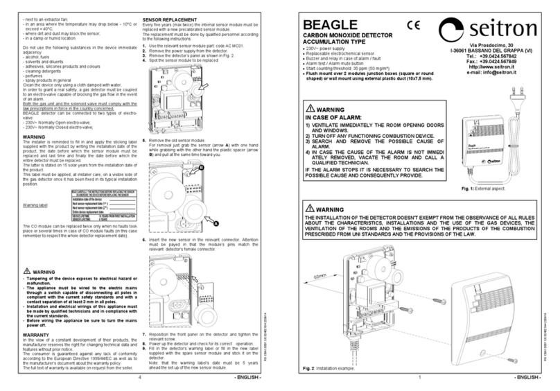
Seitron SEGUGIO L WIRELESS User manual

1
DDMSM30001T5 031751 250219
CARACTERISTICI GENERALE
Funcţionare în modalitatea via radio
Alimentare 230V
Versiune pentru GPL: (SEGUGIO L WIRELESS)
Versiune pentru gaz metan: (SEGUGIO M WIRELESS)
Senzor cu semiconductor interschimbabil
Alarmă la bord
Buton de test alarmă
Fixare pe carcase încastrate 2 module (pătrate şi rotunde)
FUNCŢIONARE
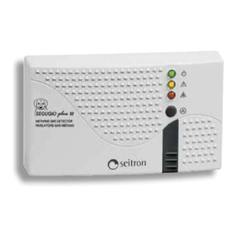
Detectorul SEGUGIO (Fig. 1) este un aparat pentru detectarea
prezenţei gazelor inflamabile via radio. În prezenţa gazelor în
concentraţie mult mai mică decât pragul de periculozitate,
activează Led-ul roşu şi buzzer.
Notă: Se poate ca utilizatorul să simtă prezenţa gazelor înainte să
intervină detectorul, având în vedere că, din motive de siguranţă,
firmele distribuitoare adaugă gaze odorizante gazului metan sau
GPL-ului.
Această senzaţie e foarte variabilă de la un subiect la altul şi
depinde de perioada de expunere.
Dispozitivul e dotat cu un buton-test ' '.
Apăsarea butonului de testare ' ' intră în modul de testare:
LED-urile verde, galben, roşu şi soneria se aprind.
SEGUGIO e dotat cu o linie de temporizare care evită intervenţia
sistemului de alarmă în timpul perioadei de stabilizare a senzorului
adică atunci când dispozitivul este, alimentat sau, la restabilire,
după o întrerupere a tensiunii de la reţea. În timpul acestei
perioade de temporizare, aproximativ 30, de secunde, se aprinde
becul de semnalizare galben "avarie" împreună cu becul de
semnalizare verde fix indicând că aparatul funcţionează.
SEGUGIO mai prevede un sistem de autodiagnosticare pentru a
verifica buna funcţionare a senzorului.
Când se aprinde becul de semnalizare galben "avarie", după
temporizarea iniţială, cauzele posibile sunt:
- senzor defect;
- senzor deconectat;
- funcţionare defectuoasă a aparatului.
Şi situaţia de "avarie" se transmite prin radio la receptor, drept
pentru care receptorul semnalizează avaria vizual şi în plus
activează releul de ieşire "avarie".
CARACTERISTICI TEHNICE
Alimentare: 230V 50Hz
Putere absorbită: 3VA
Tip senzor: SnO2cu semiconductor
interschimbabil
Gaz detectat: SEGUGIO L WIRELESS: GPL
SEGUGIO M WIRELESS: Gaz Metan
Prag de calibrare: 10% L.E.L.
Frecvenţă: 868,150 MHz
Sensibilitate: -105 dBm
Modulare: GFSK
Putere RF max transmisa: 1 mW
Lăţime bandă (-3 dB): 100 KHz
Tip antenă: tijă interioară
Distanţa maximă de la transmiţător: >300m în câmp deschis
>50m în interiorul clădirilor
(în funcţie de clădire şi de
mediu)
Semnalizări: Activare: Led verde
Alarmă: Led roşu
Avarie: Led galben
Alarmă: Sonerie - Buzzer intern
Timp de activare : ~ 30 secunde
Fig. 1: Aspect exterior.
SEGUGIO WIRELESS
DETECTOR DE SCAPARI GAZE VIA RADIO Via del Commercio, 9/11. 36065 Mussolente (VI)
- ROMANA -
ATENŢIE!
- Înainte de a instala detectorul de gaze via radio în
poziţia dorită e necesar să se controleze dacă receptorul
îşi primeşte corect semnalele sale.
- Manevrarea gresită a aparatului expune la un posibil
pericol de scurt-circuitare sau functionare defectuoasa.
- Conectaţi aparatul la reţeaua electrica printr-un
întrerupător monopolar conform normelor în vigoare şi
cu distanţa de deschidere a contactelor de cel puţin 3
mm la fiecare pol.
- Instalarea şi branşarea electrica a dispozitivului trebuie
să fie efectuate de companii autorizate cu personal
calificat şi conform legilor în vigoare.
- Înainte de a efectua orice branşare asiguraţi-vă că
reţeaua electrică e deconectată.
ATENŢIE
INSTALAREA DETECTORULUI DE GAZE NU EXONEREAZĂ DE RESPECTAREA
TUTUROR REGULILOR REFERITOARE LA CARACTERISTICI, INSTALAREA ŞI
FOLOSIREA APARATELOR PE GAZ, AERISIREA ÎNCĂPERILOR ŞI
EVACUAREA PRODUSELOR DE ARDERE PREVĂZUTE DE NORMELE UNI ŞI
DE DISPOZIŢIILE LEGALE.
ATENŢIE!
În
caz
de
alarmă
:
1) Stingeţi toate flăcările libere / neprotejate.
2) Închideţi robinetul contorului de gaze sau al buteliei de GPL
3) Nu aprindeţi şi nu stingeţi lumini; nu activaţi aparate sau dispozitive
alimentate electric.
4) Deschideţi uşile şi ferestrele pentru aspori ventilarea ambientului.
Dacă alarma încetează e necesar s identificaţi cauza care a provocat-o şi să
procedaţi în consecinţă.
Dacă alarma continuă şi cauza prezenţei gazului nu se poate identifica şi
elimina părăsiţi imobilul şi, din exterior, anunţaţi serviciul de intervenţie de
urgenta.
INSTALAREA
Rapiditatea de intervenţie a aparatului este strâns legată de
pozitionarea sa în incapere şi de tipul de gaz de detectat. Pentru
gazele "grele" cum ar fi GPL e indicat să instalati detectorul in
partea de jos (aprox. 30cm de podea) iar pentru gazele "uşoare"
cum e gazul metan in partea de sus (aprox. 30cm de la tavan).
A se evita instalarea detectorului în toate acele poziţii în care
funcţionalitatea i-ar putea fi compromisă, ca de ex.:
- într-un spaţiu închis (ex. într-un dulap sau în spatele unei
perdele);
- deasupra unei chiuvete;
- lângă o uşă sau o fereastră;
- lângă un extractor de aer / hota;
- într-o zonă unde temperatura poate coborî sub 10°C sau poate
depăşi +40°C;
- într-un loc unde murdăria şi praful pot bloca senzorul;
- într-o încăpere umedă.
Nu folosiţi următoarele substanţe în imediata apropiere a
aparatului:
Durata de viata a senzorului: 5 ani
Temperatura de funcţionare: 0°C .. 40°C
Temperatură stocare: -10°C .. +50°C
Limite umiditate: 20% .. 80% RH
(fără condens)
Grad de protecţie: IP 42
Carcasa: Material: ABS V0 care se stinge singur
Culoare: Capac: Alb semnal (RAL 9003)
Piese: Gri şobolan (RAL 7005)
Dimensiuni: 148 x 84 x 40 mm
(L x H x h)
REFERINŢE NORMATIVE
Produsul corespunde normativei pertinente de preluare a Uniunii
Europene: EMC (2014/30/UE) - LVD (2014/35/UE) - RoHS2
(2011/65/UE) - RED 2014/53/UE
ETSI EN 300 220-1
ETSI EN 300 220-2
ETSI EN 301 489-1
ETSI EN 301 489-3
EN 50581 (2012)
EN 50194-1 (2009)
EN 50270 (2006)
GARANŢIE
În perspectiva unei dezvoltări continue a produselor sale,
producătorul îşi rezervă dreptul de a aduce modificări datelor
tehnice şi prestaţiilor fără preaviz. Consumatorul are garanţie
pentru defectele de conformitate ale produsului conform Directivei
Europene 1999/44/EC precum şi documentului asupra politicii de
garanţie a producătorului.
La cerere e disponibil la vânzător textul complet al garanţiei.
METHANE
METANO
SEGUGIO
LPG
GPL
SEGUGIO
Led On/Off
Led Fault
Led Alarma
Tasta Reset

2
DDMSM30001T5 031751 250219
- alcool, benzină
- solvenţi şi diluanţi
- lipici, vopsele sau produse cu silicon
- detergenţi pentru curăţenie
- parfumuri
- spray în general
Pentru a curata dispozitivul folositi NUMAI o carpa
umezita in apa.
Instalaţia de gaze si electrovana ce se conecteaza la Receiver
trebuie să corespundă cerintelor legale în vigoare din ţara interesată
Pentru a verifica eficienţa corectă a senzorului aparatului este
disponibilă o butelie de gaz pentru teste (opţională) care trebuie să
se folosească în conformitate cu indicaţiile care i se anexează.
ATENŢIE: Folosirea oricărei alte metode de probă, cum ar fi
cu bricheta, vapori inflamabili etc. poate duce la concluzii
greşite precum şi la avarierea ireversibilă a însuşi
senzorului.
ATENŢIONĂRI
Se aminteşte instalatorului să completeze şi să pună eticheta
adezivă furnizată împreună cu produsul indicând data instalării
aparatului, data până la care să se înlocuiască pentru prima oară
modulul senzorului, data până la care să se înlocuiască a doua
oară şi ultima data modulul senzorului şi in sfârşit data până la
care să se înlocuiască întregul aparat. Aceasta din urmă
corespunde cu 15 ani calendaristici de la data instalării aparatului.
Eticheta trebuie pusă prin grija instalatorului pe o parte a
aparatului vizibilă în poziţia tipică de instalare.
Etichetă atenţionări:
Senzorul poate fi înlocuit maxim de două ori şi numai de către
persoane calificate.
Pentru a instala dispozitivul efectuaţi următoarele
operaţiuni:
1. ACCESAŢI PĂRŢILE INTERNE
Pentru a accesa părţile interne ale detectorului de gaze,
deşurubaţi şurubul care se află sub lamela de strângere dispus
pe partea din faţă (Fig. 2).
2. Fixaţi baza detectorului de gaze pe o cutie de joncţiune cu 2
module prin intermediul celor două locaşuri pentru şuruburi cu
interax de 60 mm având grijă să faceţi să treacă cablurile în
fantă aşa cum se arată în Fig. 3.
ATENŢIE:
Instalarea dispozitivului este prevăzută pentru montarea în cutii de
joncţiune cu încastrare (sau pe perete) standard cu două module şi
branşări cu cablurile subterane existente şi provenind de la
instalaţia electrică fixă.
Siguranţa şi funcţionalitatea aparatului sunt garantate numai cu o
branşare care să exploateze trecerea pentru cabluri prevăzută la
baza din material plastic.
- ROMANA -
3. LEGATURILE ELECTRICE
Urmaţi schema de conectare redată în Fig. 5.
Bornele L şi N alimentează detectorul de gaze şi trebuie
conectate la tensiunea de reţea 230V ~ cu nulul pe borna N.
4. ÎNCHIDEŢI DISPOZITIVUL
Introduceţi capacul în locaşul special, înşurubaţi respectivul
şurub şi reintroduceţi lamela ce acopera şurubul.
5. ALIMENTAŢI DETECTORUL DE GAZE
6. CONFIGURAREA SISTEMULUI RADIO
Activati modalitatea de "Auto-Asociere" apasand de 2 ori
rapid consecutiv (dublu- click) tasta ‘A’, vizibila in Fig. 4.
In modalitatea "test" detectorul de gaztrasmite continuula
receiver o comanda de “alarma” urmata de o comanda de “nicio
alarma" la doua secunde; de fiecare data cand detectorul de
gaz transmite o comanda radio, led-ul rosu vizibil in ‘B’ din Fig. 4
va lumina o data scurt. Demaraţi procedura de "învăţare
automată" pe receptor în scopul de a determina memorarea de
către receptor a adresei detectorului de gaze transmiţător.
Modalitatea Test se finalizeaza apasand o data tasta "A"
vizibila in Fig. 4 sau se termina automat dupa circa 17 minuti.
Când se dispune detectorul de gaze în zona dorită, asiguraţi-vă că
cele două dispozitive mai comunică încă în mod corect. Calitatea
semnalului se poate monitoriza pe receptor, vedeti respectiva
documentaţie pentru mai multe informaţii.
ATENŢIE!
Dacă intensitatea semnalului primit de receptor nu e
acceptabilă încercaţi să schimbaţi poziţia receptorului sau
transmiţătorului sau eventual evaluaţi posibilitatea de a
instala un dispozitiv de repetare (DA0411) care dublează
fluxul comenzilor radio. Nu uitaţi că atât transmiţătorul cât
şi receptorul trebuie să fie montate departe de obiecte
metalice sau pereţi consolidaţi metalic care ar putea slăbi
semnalele radio.
7. COMPLETAŢI ŞI PUNEŢI ETICHETA DE ATENŢIONĂRI
(A se vedea paragraful "ATENŢIONĂRI").
SCHEME DE CONECTARE
Fig. 5: Schema legaturilor pentru conectarea detectorului de
gaze la reţeaua electrică.
Fig. 2
ÎNLOCUIREA SENZORULUI
La fiecare cinci ani (ptr max.de două ori) e necesar să se
înlocuiască placuta-modul cu senzor din interiorul detectorului cu
un modul nou cu senzor precalibrat. Operaţia de înlocuire trebuie
efectuată de personal calificat conform următoarelor indicaţii:
1. Folosiţi modulul-senzor de schimb, special aferent:
SEGUGIO L WIRELESS: AC MG01
SEGUGIO M WIRELESS: AC MM01
2. Întrerupeţi alimentarea detectorului.
3. Îndepărtaţi capacul cum se arată în Fig. 2.
4. Identificaţi modulul senzor de înlocuit.
5. Scoateţi / extrageti vechiul modul senzor.
Pentru a-l scoate e suficient să luaţi modulul cu două degete
de marginile placutei senzorului (cum evidenţiază săgeţile) şi
să trageţi orizontal spre sine.
6. Luaţi noul modul senzor şi introduceţi-l în conectorul
special, având grijă să coincidă conectorul modulului cu
cel al detectorului.
ATENŢIE: Componentele Modulului Senzor
trebuie sa fie orientate catre dreapta.
7. Introduceţi capacul în lacaşul special şi înşurubaţi respectivul
şurub.
8. Alimentaţi detectorul şi verificaţi funcţionarea.
9. Completaţi eticheta de atenţionări anterior pusă pe detector
sau aplicaţi şi completaţi noua etichetă de avertizări
furnizată în dotarea modulului senzor de schimb.
Nu uitati că data corespunde cu 5 ani calendaristici de la
data punerii în funcţiune a noului modul senzor.
Importator / Reprezentant Unic si
Centru asistenta - BALCANI
GazPro Equipments srl
str.Pastorului nr.4sector 2
Bucuresti, Romania
Tel.: 0722-745312; 0745040429
E-mail: gazproequipments@gmail.com
Web: https://www.gazproequipments.ro
CITIŢI CU ATENŢIE INSTRUCŢIUNILE ÎNAINTE DE A ÎNLOCUI
SENZORUL. ÎNTRERUPEŢI ALIMENTAREA ELECTRICA ÎNAINTE DE A
ÎNLOCUI SENZORUL.
Data instalării aparatului: __________________
Data viitoarei înlocuiri (1^) a senzorului: __________________
Data viitoarei înlocuiri (2^) a senzorului: __________________
Data înlocuirii aparatului: __________________
DURATA DE VIATA A APARATULUI: 15 ANI DE LA PRIMA
INSTALARE DURATA DE VIATA A SENZORULUI: 5 ANI
Fig. 3
LPG
GPL
SEGUGIO
Fig. 4
A
B

3
DDMSM30001T5 031751 250219
- ENGLISH -
WARNING!
- Before the installation of the wireless gas detector in
the desired location, it is necessary to check that its
signals are properly received by the receiver.
- Tampering of the device exposes to electrical hazard or
malfunction.
- The appliance must be wired to the electric mains
through a switch capable of disconnecting all poles in
compliance with the current safety standards and with a
contact separation of at least 3 mm in all poles.
- Installation and electrical wirings of this appliance must
be made by qualified technicians and in compliance with
the current standards.
- Before wiring the appliance be sure to turn the mains
power off.
GENERAL FEATURES
Wireless operated
230V Power supply
LPG model: (SEGUGIO L WIRELESS)
Methane gas model: (SEGUGIO M WIRELESS)
Interchangeable semiconductor sensor
Built-in buzzer
Alarm test button
Mounting on built-in 2 module boxes (round and square)
OPERATION
The SEGUGIO detector (Fig.1) is an instrument for the wireless
detection of flammable gases. In presence of gas concentrations
far below the hazard threshold, it activates a red light and an
alarm.
Note: The user may detect the presence of gas before detector
intervention, given that distribution companies add odorants to
Methane or LPG gases.
This sensation varies widely among different individuals and
depends on exposure time.
The device is equipped with a ‘ ‘ test button.
By pressing the ' ' button, the test mode is activated: the
green, yellow and red led are lit on and the buzzer turns on.
SEGUGIO has a delay line that prevents the intervention of the
alarm system during sensor stabilization time, i.e. when the device
is powered up or it is on reset, after a mains cut off.
During this delay time, 30 seconds approx., the “fault” yellow
light lights up at the same time with the steady green light
indicating that the device is active.
SEGUGIO is also provided with a self-diagnosis system to check
the proper operation of the sensor.
If the “fault” yellow light turns on after the initial delay, the
probable causes are the following:
- sensor is faulty;
- sensor is disconnected;
- malfunctioning of the instrument.
Also the “fault” status is transmitted via radio to the receiver , so
that the receiver visually signals the fault and switches on the
“fault” output relay.
TECHNICAL FEATURES
Power supply: 230V 50Hz
Power absorption: 3VA
Sensor type: Semiconductor SnO2,
replaceable
Detected gas: SEGUGIO L WIRELESS: LPG
SEGUGIO M WIRELESS: Methane
Calibration threshold: 10% L.E.L.
Frequency: 868,150 MHz
Modulation: GFSK
Max. RF power transmitted: 1 mW
Bandwidth (-3 dB): 100 KHz
Antenna type: Internal stylus
Max. distance from the receiver: >300 m in free air
>50 m in building
(depending on the building
and environment)
Indicators: Operation: Green led
Alarm: Red led
Fail: Yellow led
Alarm: Buzzer
Activation delay: ~ 30 seconds
Sensor lifetime: 5 years
Operating temperature: 0°C .. 40°C
Storage temperature: -10°C .. +50°C
Fig. 1: External aspect.
Via del Commercio, 9/11. 36065 Mussolente (VI)
WARNING
THE INSTALLATION OF THE DETECTOR DOESN'T EXEMPT FROM THE
OBSERVANCE OF ALL RULES ABOUT THE CHARACTERISTICS,
INSTALLATIONS AND THE USE OF THE GAS DEVICES, THE VENTILATION
OF THE ROOMS AND THE EMISSIONS OF THE PRODUCTS OF THE
COMBUSTION PRESCRIBED FROM UNI STANDARDS AND THE PROVISIONS
OF THE LAW.
WARNING! In case of an alarm:
1) Extinguish all fire sources.
2) Close main gas valve (either methane or LPG).
3) Do not turn on or off any electrical light; do not turn on or off any
electrical device.
4) Open doors and windows to increase ventilation.
If the alarm stops it is necessary to search the possible cause and
consequently provide.
In case the alarm persists and the cause of the leak cannot be found,
vacate the premises and, from external, immediately notify the gas
emergency service.
INSTALLATION
Please note that the intervention delay is strictly dependant both
on a correct positioning of the detector in the room and to the
type of gas to be detected.
In case of 'heavy' gases as for LPG an installation in low places is
advisable (roughly 30 cm from floor), instead for ’light’ gases as
for methane in high places (roughly 30 cm from ceiling).
Please avoid to install this gas detector in any position in which its
operational features could be compromised, such as the following:
- in a closed space (e.g. in a cupboard or behind a curtain);
- directly above a sink;
- next to a door or window;
- next to an extractor fan;
- in an area where the temperature may drop below - 10°C or
exceed + 40°C;
- where dirt and dust may block the sensor;
- in a damp or humid location.
Do not use the following substances in the device immediate
adjacency:
Humidity limits: 20% .. 80% RH
(non condensing)
Protection grade: IP 42
Case: Material: ABS V0 self-extinguishing
Color: Cover: Signal white (RAL 9003)
Details: Mouse grey (RAL 7005)
Size: 148 x 84 x 40 mm
(WxHxD)
NORMATIVE REFERENCE
The product complies with the relevant European Union standards:
EMC (2014/30/UE) - LVD (2014/35/UE) - RoHS2 (2011/65/UE) -
RED 2014/53/UE
ETSI EN 300 220-1
ETSI EN 300 220-2
ETSI EN 301 489-1
ETSI EN 301 489-3
EN 50581 (2012)
EN 50194-1 (2009)
EN 50270 (2006)
WARRANTY
In the view of a constant development of their products, the
manufacturer reserves the right for changing technical data and
features without prior notice. The consumer is guaranteed against
any lack of conformity according to the European Directive
1999/44/EC as well as to the manufacturer’s document about the
warranty policy. The full text of warranty is available on request
from the seller.
METHANE
METANO
SEGUGIO
LPG
GPL
SEGUGIO
SEGUGIO WIRELESS
WIRELESS GAS LEAK DETECTOR
On/Off led
Fault led
Alarm led
Reset button

4
DDMSM30001T5 031751 250219
- ENGLISH -
- alcohol, fuels
- solvents and diluents
- adhesives, silicones products and colours
- cleaning detergents
- perfumes
- spray products in general
Clean the device only using a cloth damped with water.
Both the gas unit and the solenoid valve at the receiver side must
comply with the law prescriptions in force in the country
concerned.
In order to check the proper efficiency of the device sensor a
specific test gas bottle (optional) is made available which must be
used according to the enclosed instructions.
WARNING: Any other method for testing, such as the use of
cigarette lighters, flammable vapours etc., can lead to
wrong conclusions as well as to the irreversible damage of
the sensor itself.
WARNINGS
The installer is reminded to fill in and apply the sticking label
supplied with the product by writing the installation date of the
product, the date before which the sensor module must be
replaced, the date before which the sensor module must be
replaced the second and last time and finally the date before
which the entire detector must be replaced. The latter is stated on
15 solar years from the installation date of the product. This label
must be applied, at installer care, on a visible side of the gas
detector once it has been fixed in its typical installation position.
Warning label:
The sensor module can be replaced only twice and the
replacement must be done by qualified personnel only.
To install the device carry out the following steps:
1. ACCESS TO THE INTERNAL COMPONENTS
To access the internal components of the gas detector, loose
the screw under the raw plug on the front panel (Fig. 2).
2. Attach the base of the gas detector to a 2 module junction box
through the two screw slots with a hole to hole distance of
60 mm ensuring that wiring is made through the cable slot as
shown in Fig. 3.
ATTENTION:
This device is intended for mounting on standard built-in (or wall-
in) 2-module junction boxes and electrical connection through the
existing chased wiring from the fixed electrical system.
Safety and performance of this device can be guaranteed only
when the electrical wiring is properly made through the cable slots
provided for on the plastic base.
3. ELECTRICAL CONNECTIONS
Follow the wiring diagram shown in Fig.5.
The gas detector is powered by terminals L and N which are to
be connected to the 230V~ mains supply with neutral on
terminal N.
4. CLOSE THE DEVICE
Reposition the front panel on its seat, tighten the screw and
insert the screw cap.
5. POWER UP THE GAS DETECTOR
6. RADIO SYSTEM SET-UP
Switch on to "Self-learning procedure" by rapidly pressing twice
(double click) the ‘A’ button, shown in Fig. 4.
When in “test” mode the gas detector continuously transmits to
the receiver an “alarm” command followed by a “no alarm”
command every two seconds; every time the gas detector
transmits a radio command, the red led shown in Fig. 4 as ‘B’
blinks once.
Start the “self-learning procedure” on the receiver to memorize the
transmitter gas detector address.
The "test" mode, can be stopped by pressing once the ‘A’ button,
shown in Fig. 4 or it automatically finishes after about
17 minutes.
When the gas detector is positioned in the desired position, make
sure that it still communicates properly with the receiver.
The signal quality can be monitored in the receiver; see the relative
documentation for further information.
CAUTION!
If the receiver signal strength is not acceptable, try to
change the position of the receiver or transmitter or
evaluate the possibility to install a repeater (DA0411) which
doubles the range of the radio signals.
Remember that both the transmitter and the receiver must
be installed away from metal objects or metal-reinforced
walls that could weaken the radio signals.
7. COMPLETE AND ATTACH THE WARNING LABEL
(See paragraph "WARNINGS").
WIRING DIAGRAMS
Fig. 5: Wiring diagram for the connection of gas detector to the
main supply.
Fig. 2
SENSOR REPLACEMENT
Every five years (max twice) the internal sensor module must be
replaced with a new precalibrated sensor module.
The replacement must be done by qualified personnel according to
the following instructions:
1. Use the relevant sensor module part:
SEGUGIO L WIRELESS: AC MG01
SEGUGIO M WIRELESS: AC MM01
2. Remove the power supply from the detector.
3. Remove the detector panel as shown in Fig. 2.
4. Spot the sensor module to be replaced:
5. Remove the old sensor module, holding firmly the edges of
the board and pulling it out:
6. Insert the new sensor in the relevant connector. Attention
must be payed in that the module pins match the relevant
detector female connector.
WARNING: The sensor module must be installed
with its components facing to the right.
7. Reposition the front panel on the detector and tighten
the relevant screw.
8. Power up the detector and check for its correct operation.
9. Fill in the detector warning label or fill in the new label
supplied with the spare sensor module and stick it on
the detector.
Note: that the warning label’s date must be 5 years ahead
the set up of the new sensor module.
Importator / Reprezentant Unic si
Centru asistenta - Balcani
GazPro Equipments srl
str.Pastorului nr.4 sector 2
Bucuresti, Romania
Tel.: 0722-745312; 0745040429
E-mail: [email protected]
Web: https://www.gazproequipments.ro
Fig. 3
LPG
GPL
SEGUGIO
Fig. 4
A
B
This manual suits for next models
1
Table of contents
Languages:
Other Seitron Security Sensor manuals
Popular Security Sensor manuals by other brands

Datasensing
Datasensing S3N-PR T5 Series manual

NuAire
NuAire 230PIR installation guide

Honeywell
Honeywell IntelliSense FG-1625RFM installation instructions

Bircher Reglomat
Bircher Reglomat Jupiter operating instructions

Honeywell
Honeywell IQ Force Operation manuals

DigiSpec
DigiSpec VMD-1001 Operation manual