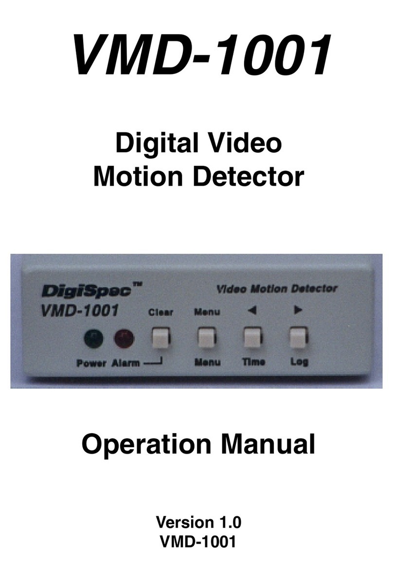
DigiSpec VMD-1001 User manual

VMD-1001
Digital Video
Motion Detector
Version G
Operation Manual

Introduction ..................................................................... 3
Features ........................................................................... 4
Connecting the Video .................................................... 6
Types of Cameras .............................................. 6
Cable .................................................................... 6
Lighting ................................................................ 7
Video Input & Output ........................................ 7
Connecting the Alarms ................................................. 8
Alarm Output ....................................................... 8
Connecting the Power .................................................. 9
Normal Operating Mode ................................................ 10
Front Panel .......................................................... 10
Button Operation ................................................ 10
On-Screen Displays ....................................................... 12
Present Time Display ........................................ 12
Log Display ......................................................... 13
Video Loss .......................................................... 13
Programming the VMD1001
Main Menu .............................................................................. 14
Security Code .........................................................................15
Alarm Setup .......................................................... 17
Sensitivity Level ................................................ 17
Tracking Level .................................................... 18
Relay Hold ........................................................... 19
Relay Contact ..................................................... 19
Buzzer .................................................................. 19
Alarm Zones ........................................................ 20
Clock Format ...................................................... 20
Clock Set ............................................................. 21
Alarm Log / Clearing ......................................... 22
Warranty ........................................................................... 24
Specifications ..................................................................... 26
Emergency Security Code Tear Out Page ........................................... 27
2
TABLE OF CONTENTS

INTRODUCTION
Congratulations on your purchase of the VMD-1001 Digital Video Mo-
tionDetector.You are now the owner of one of the most innovative, low
cost video motion detectors available today. We would like to person-
ally thank you for your purchase and would like to provide you with
additionalinformationonthisremarkableproduct.TheVMD-1001analy-
ses the video image 30 times per second to assure instantaneous
motiondetection.ByutilizingRISC processing, the VMD-1001 handles
millions of calculations per second, which greatly decreases the deci-
sion time and increases reliability.
Traditionally, motion detection has been used for surveillance and se-
curity applications. This unit is perfect for indoor or outdoor, low light
and difficult applications. Regardless of the job, the VMD-1001 can
handleit.
This ground breaking technology is representative of our commitment
toincorporateQuality,Valueand Innovationineveryproductwemanu-
facture. We are and will continue to be the leader in Digital Video Mo-
tion Detection Technology.
3

FEATURES
- Compact Size
- Simple Installation and Easy Set up
- 198 Independently Selectable Zones
- 99 Levels of Sensitivity
- Duration Settings from 0-99 seconds
- On-Screen Programming
- 100-Entry Event Log
- User Access Security Code
- No external synchronization required
- Low Power 7-15VDC @ 50mA
4

CONNECTING THE VIDEO
Type of Cameras
Precautions: The VMD-1001 functions best with high quality video
cameras.Camerasmustbesecurelylockeddownsothepictureisstable
andjitterfree.IfthepicturejittersortheVideoMotionDetector’s (VMD)
character display jitters, the VMD may false trigger. If the camera has
any sync or phase adjustments, try adjusting these first.
To select the right camera for your application (i.e. indoor, outdoor, low
light,nolight),youshouldconsidertheadvantagesanddisadvantages
of each type.
CCD: High quality CCD cameras will work well with the VMD-1001.
The higher the resolution, the more precise the motion detection. CCD
camerasworkequallywellin both indoor and outdoor enviroments.Itis
recommednded that B&W CCD cameras be used in outdoor applica-
tions due to their increased resolution. B&W low light level CCD cam-
eras should be used in low light conditions. CCD cameras are sensi-
tive to Infrared (IR) light and can be used for night vision with the aid of
anInfraredIlluminator.
IR: Infrared cameras should be used for no light applications or very
sensitive night vision applications. IR cameras are better equipped for
night vision than CCD cameras.
Cable
Itisimportantthatyouusethepropercabletype and installation proce-
dures when installing the cameras and your VMD. Make sure you use
standard RG-59U coaxial cable with at least 95% braided shield for
videotransmission. Wheninstalling,makesurethatyoudonotrunthe
cablenearanypower lines for they maycauseinterferenceinthevideo
transmission. If you are cabling between floors or long distances, use
conduit to protect the cable from interference. Proper protection of the
video cable from external power interference, weather, and water is
5

important to ensure a clear transmission of video signal and reliable
motiondetection.
Grounding problems between the various components of a video sys-
tem may cause noise or hum bars to appear in the video image. This
must be eliminated by properly grounding all equipment to an earth
groundandmaking sure allshieldsareintactinall videocoaxialcables.
Grounding problems will effect the reliability of motion detection.
Lighting & Enviromental Conditions
Unless a camera is in a controlled enviroment, fluctuations in condi-
tions will occur. The VMD-1001 provides the flexibility to configure the
Video Motion Detector for two separate sets of conditions.
Florescent Lighting: Gradualor suddenlightingchanges,video noise,
intermittenceorglitchesinvideo lines, or power surges can be ignored
bytheVMD-1001.Tocompensateforsuch occurrencesabalancemust
bereachedintheconfigurationofthemotioncriteria(seeMotionCrite-
ria). Fluorescent light may result in high speed flickering when a CCD
cameraisused. Variouscamerashaveshutter selectionsforflickerless
option or you may have to disable the Auto White balance feature on
DC versions. Another solution is to change the lighting ballast to an
electronic one that operates at a higher frequency than the video sync
signal.
Video Input / Output
The video input and output are located on the rear of the unit. (see
Figure1).Thevideoinput connects to the videosourceviatheleftBNC
connector. The video output connects to a display, recording device,
switcher, or other equipment via the right BNC connector. Both the
input and output are 1 V P-P into 75 ohms unbalanced EIA standard
RS-170A/ NTSC or CCIR / PALvideo format. Improper input termina-
tion or looping will cause the video level to be too low and effect the
motion detection. Improper output termination will make the image or
the video recording poor.
6

Alarm Output
The VMD-1001 has one Form-C alarm output with a normally open (N/
O) and normally closed (N/C) configuration. When power is lost, the
contacts are as follows.
The contacts change state (open to closed N/O, or closed to open N/
C) whenever an alarm occurs. An alarm occurs when the VMD-1001
detectsmotion andthealarmhasbeenenabledbypressing theALARM
ON-OFF button (red LED on or slow flashing). The contacts remain
closed or open for the duration programmed in the Relay Hold time.
The location of the alarm output connector is seen in Figure 1. The
state of the relay when there is no alarm can be selected as N/C or N/
Oso that power losswill indicateeither analarm orno alarm.For more
information, consult the Relay Contact Section of this manual under
Alarm Setup.
Some equipment may require a dry contact closure (normally open).
Connect such equipment to the N/O and common leads. For a nor-
mallyclosedalarm,connectbetweentheN/Candcommonleads.There
Input Output Alarm
Form-C
NO
NC
Com Power
7-15VDC
Common NO NC Figure 2 - Alarm Plug
Connecting the Alarms
Figure 1 - Back Panel Diagram
7

is no polarity; these leads may be swapped around. Other equipment
may require a closure to ground. In this case, a ground connection will
be provided on such equipment. Connect the common lead to ground
and N/O lead to the input of the equipment. There is no voltage on the
alarm connectors of the VMD-1001. No damage can be done by incor-
rectwiring.
For installation guidelines, consult the Relay Contact Section of this
manual under Alarm Setup.
Connecting the Power
The VMD-1001 operates from a DC supply range from 8V to 15VDC.
The power input connector, a standard 2.1mm power jack, must have
positive(+)onthe center and negative (-) or ground, on theouter shell.
The unit is reverse protected and correct polarity is indicated by the
green Power LED being lit on the front panel.
Formobileoperation,anegativegroundsystemisrequired,unlessthe
video ground is isolated from the automobile chassis ground. If oper-
ated in a vehicle, make sure the power supplied to the VMD-1001 is
properlyfilteredsoalternator,radioorotherequipmentdoesnotgener-
ated noise that might effect the motion detection performance. The
unitmaybeoperatedoff of a regular 110or220VAChouseholdsupply
using a transformer to supply the required 8-15VDC power.
8

NORMAL OPERATING MODE
Front Panel
Four buttons on the front panel give full control of the unit.
The two LEDs indicate the general state of the unit. The green Power
LED indicates appropriate power is applied. The red Alarm LED indi-
cates the unit is armed when solid and alarmed when flashing rapidly.
Note: Motion detection is inhibited during setup and during the time or
logdisplay.
Figure 3 - Front Panel
In the normal operating mode, the VMD is processing alarms (if en-
abled) and displaying the date and time (if enabled). The 4 buttons
provide all the necessary functions.
Alarm Button
This button toggles between alarm enabled and disabled. When en-
abled,theVMD-1001 will generate alarmswheneverthemotiondetec-
torqualifiesvalidmotion.Whenthealarmisdisabled, no alarms will be
generated. However, the red LED will still flash whenever motion is
detected. This feature is useful when setting the Sensitivity Level. The
red LED will light solid or slow flashing when the alarm is enabled.
Ifanalarm isactive(i.e.theVMD-1001isgeneratinganalarm)pressing
the Alarm button will clear the alarm. After that, the alarms will toggle
between enabled and disabled.
9
Clear Menu Z [
Menu Time Log
PowerAlarm

Menu Button
Thisbuttonbrings uptheProgrammingMenu as whitelettersoverlayed
on the video and starts the Programming Mode.
Time Button
Momentarily displays the current data and time on the screen.
Log Button
Displays Log Page #1 and starts the Log Display Mode. The most re-
cent alarm events, and their date, time, and alarm number are dis-
played. Pressing the Left or Right button scrolls forward or backward
through the log. Pressing the Clear button clears the Log Page and
reverts back to normal running operation. Normal operation also re-
sumes when no buttons have been pressed for 10 seconds.
Remember, motion detection is inhibited when the log is being dis-
played.
10

ON-SCREEN DISPLAY DURING RUNNING
OPERATION
Alarm Display
Whenever an alarm occurs, a message is shown on the bottom
lineofthescreenwhichindicatesthedateandtimeofthealarmas
wellasthenumberofaccumulatedalarms(1-99).Thisdisplaywill
continueforthedurationofmotiondetectionplustheprogrammed
alarm Hold time. In USA and 12 hour format, the display will ap-
pearasfollows.
MM/DD/YY HH:MM:SS A##
where## isthenumberofalarms accumulatedsincelastclearing
thelog.
Present Time Display
Thesystemdate andtime willmomentarilydisplay wheneverthe
Timebuttonispressed.
PRESENT TIME
MM-DD-YY HH:MM:SSA
MM-DD-YY
Month(01=JAN, 02=FEB,etc.) Date(dayofthemonth)andYear.
ThesequenceofthesecanbechangedintheClockFormatMenu.
USAorEuropeanformatsare selectable.
HH:MM:SSA
Hours, minutes, seconds, and am/pm indicators. The format can
be changed in the Clock Format Menu to display 12 hour mode
(with am/pm) or 24 hour mode (military time). The method used
heredetermines themode fortheTimerMode menuscreen.
11

Log Display
PressingtheLogbuttonwilldisplaythealarmlog,eightalarmsata
time,starting withthe mostrecentasnumber1.
Sample Alarm Log:
Alarm Log 01 <=note:pagenumber, pressLeft
04/02/99 08:05A 01 & Right to scroll through the
04/02/99 08:02A 02 pages of alarm events
04/01/99 03:25P 03
03/25/99 12:15P 04 <= each entry is: date, time,
and alarm number
Video Loss
When video is lost, the VMD stops all processing. An alarm will
occurimmediately andwillbedisplayedaccordingly.
12

Programming the VMD1001
To starttheprogramming,press theMenubutton.TheMain Menu
page will be displayed.
Main Menu
MAIN MENU
-> SECURITY CODE
ALARM SETUP
ALARM ZONES
CLOCK FORMA
CLOCK SET
ALARM LOG
The6itemsontheMainMenuarethe maincatagories forsetting
the VMD. From this menu, you branch to the menu page associ-
atedwith eachitem, wherethe settingsare changed.
Duringprogramming,thefourbuttonsfunctionasfollows:
Clear Button
Clears the programming mode at any time during programming
andrevertsbacktonormalrunningoperation.Changeswillbesaved
tonon-volatile memoryand willtakeimmediateeffect.
Menu Button
Steps through the programming options which are displayed on-
screenwithflashingprompts.EachtimetheMenuButtonispressed,
thenextpromptwillbeselected,indicatingachangecanbemade.
Atthe endofeachmenupage,thelast promptwillwraparoundto
13

the top of the page (the first prompt).
Left Button
Use this button to reduce the value if it is numeric or to sequence
backwards if the value is text. During zone pattern settings, the
cursorwillmove tothe left.Holdingdownthebutton willcause its
actiontorepeatrapidly.
Right Button
Use this button to increase the value if it is numeric or sequence
forwardsif thevalueistext.DuringZonePattern settings,thecur-
sor will move to the right. Holding down the button will cause its
actiontorepeatrapidly.
Security Code
SECURITY CODE
-> >00< 00 00 00
SECURITY ENABLE?
YES >NO<
ACCEPT CHANGES?
YES >NO<
Asecuritycodemaybe setusing thismenu topreventaccidental
changes to the alarm criteria settings and subsequent missed
alarms.
TheSecurityCode is essentiallyapassword that consistsoffour
groupsofnumbers(eachfrom 00to 99)
14

To set a security code, access this menu from the main menu by
selectingSecurityCodeusingtheMenubutton.Whentherightar-
row is pointing to the Security Code, press the Log or Right (>)
arrowbutton.ThenMenubuttonmovestheflashingcursor><around
thescreen.Movethecursortothesetofnumbersyouwishtochange
andthenusetheLeft orRightarrow buttonstochangethevalue.
For example, to set a security code of: 01 02 03 04, move the
cursortothefirstsetofzeros(00)usingtheMenubuttonandpress
theRight arrowoncetochangethevalueto “01”
PresstheMenubuttontomovetothenextgroupofzeros(00)and
again press the Right arrow to change this value to “02”. Repeat
thisfor thethird andfourth sets toset“03”and“04”respectively.
Next,usingthe Menubutton, movethe cursortothe SecurityEn-
able?prompt andpress theRight arrowbutton totoggle to“Yes”.
Finally,movethecursortotheAcceptChanges?promptandtoggle
to“Yes”.
Onceyouhavesetthecode,enabledit,andacceptedthechanges,
pressthe Clearbuttontoexitthismenu.
Atthis point,thesecuritycodenumbersyouset willberequiredto
enter the Programming menu. Page 27 is provided to record the
securitycode.
15

Alarm Setup
TheAlarm Setupmenuisthemostimportantsetupforthe opera-
tionofthemotiondetector.Itisusedtoadjustcriteriaforqualifying
avalid alarm.
ALARM CRITERIA
SENS >02<
TRACK 0.1
HOLD 0.05
RLY CONTACT
>NC< N0
BUZZER
ON >OFF<
The Two Motion Detection Criteria
There are 2 motion detection criteria for qualifying an alarm with
respectto contrastfrom background,and durationofmotion.
Sensitivity Level adjusts for the size of a moving object that will
trigger an alarm. A small object requires a higher sensitivity level
totrigger.Alargerobject willtriggerat alowersensitivity.TheSen-
sitivityLevelhasarange ofbetween 1and99.
Each camers’s sensitivity must be set individually and adjusted
according to its use. Use the Menu button to highlight the SENS
settingand eitherincreaseordecreasethe valueusingtheLeftor
Rightarrowbuttons. Therightarrowbutton willincreasethesensi-
tivity,andtheleftarrowbuttonwill decreasethesensitivity.
Configuration Hints: To assist in adjusting the sensitivity, dis-
ablethealarm(redLED off)using theAlarm button.TheredLED
willilluminate onlywhen motionis detected.If itblinks oftenwhen
16

there is no motion, the sensitivity is too high. If the LED does not
illuminatewith motion,thesensitivityistoolow.
Inoutdoor applications,variablessuchasshadows, precipitation,
etc.callforlowersensitivity.Theseconditionscanbescreenedout
so only relevant motion is detected. Experimentation will provide
helpfulinformationindeterminingthecorrectlevel.
Thesensitivitymustbesetappropriatelyforeachcameralocation.
Ifthesensitivityistoolow,analarmmayneveroccur.Ifthesensitiv-
ityistoohigh,shadowsandnoisemayfalselytriggeralarms.Power
inducednoise,thermalnoise,andsnowfromthecameraaretypes
ofnoisethatmaycausefalsetriggeringifthesensitivityistoohigh.
To filter out noise, set the sensitivity to a maximum and decrease
until the false alarms are stopped. Use the Alarm OFF mode to
detect false alarms by showing a motion trigger as a flash of the
Alarm LED.
Tracking Level is the length of time, in tenths of a second, that
motionmustbecontinuouslyoccuringtoactivatethealarm.Track-
ingcanbesetfor 0.0secondsfor instantaneoustriggeringorfrom
0.1to 8.0seconds fortriggering equalto thatnumber ofseconds.
TheTrackingiscrucialtomotion calculation.
Trackingcanfilteroutunwantedorrandommotion.Itmustbesuffi-
ciently long to filter out this motion, but short enough to capture
requiredevents.
Use the Menu button to highlight the Track setting and either in-
creaseordecreasethevalueusingtheLeftorRightarrowbuttons.
Configuration Hints:TheTrackingcriteriamakestheVMD-1001
excellentforoutdoors.Byincreasingthenumberofseconds,many
naturaloccurencescanbemaskeout.Forexample,lightning will
lastnomorethan0.4seconds.Acamerashakinginthewindtakes
perhaps0.5 to 0.6seconds.Similarly, atreebranch shaking bya
17

gustofwind mighttake1.0second. Ifthe trackingistoo low,sud-
den changes such as lighting, insects near the camera, flashing
lights, snow, andrain mayfalsely triggeralarms.TheTracking at-
tributecanrequireupto8.0secondsofcontinuousmotionwhichis
morethan sufficientto maskout mostnatural phenomenaas well
asintermittentmotion. IftheTracking isset toohigh,therequired
objectmovingintheimage maynot triggeran alarm.Thus,a bal-
ance between required and unwanted motion must be achieved.
Experimentationisrequiredtoproperly setthis alarmcriteria.
HOLDisthelengthoftime(inseconds)thattherelaywilloutputan
alarmcondition toanexternaldevicebefore itresets.Itcanbe set
from0:00to3:00minutesinincrementsofseconds.UsetheMenu
buttontohighlighttheHoldsettingandeitherincreaseordecrease
thevalueusingtheLeftorRightarrowbuttons.
Configuration Hints: Thelengthoftimeyouwilloutputanalarm
depends on the type of device being controlled. A light or a bell
may require a longer alarm time. An external matrix switcher or
VCRwillusuallyrequireonlyapulse.Inthiscase,youmaywantto
setthe alarmoutputtimeto1second.
RLY CONTACT allows you to select whether the relay contacts
youusewillbenormallyclosed(NC)ornormallyopened(NO)dur-
inganalarm.UsetheMenubuttontohighlightthe RLYCONTACT
setting and either select NC or NO using the Left or Right arrow
buttons.
The BUZZER simply allows you to enable or disable an internal
alarmbuzzer.UsetheMenubuttontohighlighttheBUZZERsetting
andeitherselectONor OFFusingtheLeftorRightarrowbuttons.
Pressthe Clearbuttonwhen complete.
Configuration Hints: Determine if a power failure should indi-
cateanalarmornoalarm.WithVMDpowerOFF,wireuptotheN/
O or N/C contacts of the VMD which gives the proper indication.
18

PoweruptheVMDusingtheRelayContactmenu,selecttheproper
choice(NOorNC)which indicatesnoalarm wheninfactnoalarm
exists.
Alarm Zones
By selecting Alarm Zones you are able to change the detection
zonesof thevideomotion.
Upon entering this menu, the top left most zone will be flashing a
rectangularbox.Thedefaultisallzonesactivewhichissignifiedby
therectangularbox.
To deselect a zone, press the Menu button to toggle to the white
dotinthe center ofthe zone. Thisdotsignifies thezoneis not ac-
tiveand allmotioninthiszonewillbeignored.
UsetheLeftorRightbuttontoselectthepreviousoradjacentzone.
Whenyoureachthebottomright mostzonethecursorwillwrapto
thetopleftmostzone.
ContinuousholdingoftheRightorLeftbuttonwillcausethecursor
tomove quicklytofindthecorrectzonefaster.
You can also quickly select or deselect all zones by holding the
“Menu”buttoninwhenthe on-screendisplay iseitherselected or
deselected.ThenholdcontinuouslytheLeftorRightbutton.Rapid
selectionordeselectionofthe zonesveryquicklywillthenbepos-
sible.
Clock Format
InthismenutheTimeformatcanbeconfiguredtoeither12houror
24hourformat,andtheDateto eitherUSA orEuropean format.
19

Use the Menu button to highlight theTime Format setting and ei-
therselect 12Hor 24HusingtheLeftor Rightarrown buttons.
TIME FORMAT
-> >12H< 24H
DATE FORMAT
>MDY< DMY
Use the Menu button to highlight the Date Format setting and
either select MDY or DMY using the Left or Right arrow but-
tons.
MDY: Month, Day, Year USAFormat
DMY: Day, Month, Year EuropeanFormat
Clock Set
Thismenu providesthe configurationoption ofsetting thecurrent
DateandTime.TheTimecanbe configuredforAMorPM,ifinthe
previousmenu (ClockFormat), 12hour formatwasselected.
Use the Menu button to highlight the Hours setting and either in-
crease or decrease the Hours using the Left or Right arrow but-
tons.
Use the Menu button to highlight the MINS setting and either in-
crease or decrease the Hours using the Left or Right arrow but-
tons.
20
Other manuals for VMD-1001
1
Table of contents
Other DigiSpec Security Sensor manuals
Popular Security Sensor manuals by other brands
System Sensor
System Sensor 1112/24D Installation and maintenance instructions
U-Prox
U-Prox Water user manual

MGC
MGC MIX-4030 Installation and maintenance instructions
IntelliSense
IntelliSense DUAL TEC DT-906 Series Supplemental information

Antec Scientific
Antec Scientific DECADE II SDC 174 user manual
Elko
Elko inels RFWD-100 quick start guide
