Seiwa SWx 1200 User manual

INSTALLATION MANUAL
MMSW1SEAE041
ÑMMSW1SEAE041jÓ
SWx 1200

3. Installation
3.1 Bracket mount
40 mm
[1.5”]
5.5 mm
[0.2”]
10 mm
[0.4”]
100 mm
[4”]
20 mm
[0.8”]
8 holes
1. Product description
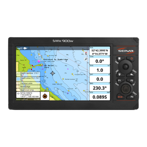
The SWx 1200 Chartplotter series features a 12” multifunctional display and SEIWA ROMEO
software. The series includes two versions: SWx 1200w and SWx 1200cw with WiFi and CHIRP
echosounder/shnder.
1.1 Content of the package
• SWx 1200w / SWx 1220cw
• Power supply / Data cable x 1
• Mounting bracket kit x 1
• Screw knob x 2
2. Technical specifications
●Display size: 12”
●Display resolution: 1024x768px
●Display brightness: 1250 nits
●Touch-screen: Capacitive multitouch
●Back-lit keyboard
●Built-in GPS sensor: 10Hz GPS/GLONASS
●Built-in Fish Finder CHIRP*
●External GPS connector
●NMEA 2000
●NMEA 0183: 2x Rx/Tx on power cable
●Transducer connector*
●Memory slot: MicroSD
●Wireless LAN connection compatibility
●Mounting options: Bracket and flush mount
●Waterproof: IPX6
●Supply voltage: 10-35 Vdc
●Operating temperature: -10°C / +60°C
●Storage temperature: -20°C / +80°C
●Transmitting frequency range: 2400 - 2483 MHz
●Maximum transmitting power: 100 mW
●Maximum power consumption: 24W (or 32W*)
* SWx 1200cw

3.3 How to insert the MicroSD
3.2 Panel mount
4. Connections scheme
* SWx 1200cw
NMEA 2000 Connector
PIN FUNCTION
1 NOT CONNECT
2 POWER +
3 POWER -
4 SIGNAL H
5 SIGNAL L
GPS Connector (Port C)
PIN FUNCTION
1POWER OUTPUT + (10-35 Vdc)
2 OUTPUT C
3 INPUT C
4 NOT CONNECT
5 NOT CONNECT
6 GND / SIGNAL RETURN
FF Transducer*
PIN FUNCTION
1 XDR POSITIVE
2 XDR SHIELD
3 TEMP
4 +5V
5 ID
6 GND
7 XDR NEGATIVE
8 SPEED
Power & I/O Connector (Port A & Port B)
PIN FUNCTION
1 GND
2 POWER INPUT + (10-35 Vdc)
3INPUT A
4 COMMON
5 OUTPUT B
6OUTPUT A
7 INPUT B
8EXTERNAL ALARM OUTPUT
274 mm
[10.7”]
204 mm
[8”]
315 mm
[12.4”]
200 mm
[7.8”]
4 holes
Ø5 mm [0.2”]
6

POWER & I/O CABLE
PIN Wire Color Function
1 Black PWR-/GND
2 Red POWER INPUT + (10-35 Vdc)
4.1 Power supply connection
3.15A FUSE
4.2 Autopilot connections
Autopilot on Port A
POWER & I/O CABLE
PIN Wire Color Function
1 Black PWR-/GND
2 Red POWER INPUT + (10-35 Vdc)
4 Green COMMON
6 Yellow OUTPUT A RX+
COMMON AUTOPILOT
3.15A FUSE
Autopilot on Port B
POWER & I/O CABLE
PIN Wire Color Function
1 Black PWR-/GND
2 Red POWER INPUT + (10-35 Vdc)
4 Green COMMON
5 Gray OUTPUT B RX+
COMMON AUTOPILOT
3.15A FUSE
WARNING: Do not connect the COMMON connections (green wires) of the I/O ports to the power cables
of external devices. This connection could damage the hardware of the device.

4.3 External alarm connection
POWER & I/O CABLE
PIN Wire Color Function
1 Black PWR-/GND
2 Red PWR + (10-35 Vdc)
8 Blue OUTPUT EXTERNAL ALARM
(Open Collector)
NOTE: Current MAX 300 mA.
3.15A FUSE
4.4 NMEA0183 connections
External NMEA on Port A
POWER & I/O CABLE
PIN Wire Color Function
1 Black PWR-/GND
2 Red POWER INPUT + (10-35 Vdc)
3 White INPUT A
4 Green COMMON
6 Yellow OUTPUT A RX+
COMMON
EXTERNAL
NMEA
DEVICE
TX+
External NMEA on Port B
POWER & I/O CABLE
PIN Wire Color Function
1 Black PWR-/GND
2 Red POWER INPUT + (10-35 Vdc)
4 Green COMMON
5 Gray OUTPUT B
7 Brown INPUT B
RX+
EXTERNAL
NMEA
DEVICE
TX+
COMMON
3.15A FUSE
3.15A FUSE
NOTE: NMEA-0183 input baud rate is automatically detected and selected. If you need to set
the baud rate manually please go into the settings menu.

5. Keyboard
The joystick can move the cursor around the map or through menu items. Press [UP], [DOWN],
[LEFT] or [RIGHT].
Each button – except for MOB – can perform two functions: a short press performs the function
labeled on the button; a long press (hold) executes the second function labeled on the unit face (for
Power key is the opposite).
[F1 – F3] long press functions can be customized by the user. This gives you a wider scope of options.
Read the software manual to learn how to customize the functions keys.
[POWER] – [BRIGHTNESS]
Short press: allows to change the brightness.
Long press: turns the device on/o when pressed and held in.
[F2] – [WP]
Short press: WP – insert a new waypoint on the cursor position.
[ZOOM IN / ZOOM OUT] – [ENTER]
Rotor: Zoom In/Out if turned on map (it is possible to change default setting to [ROTATE] or [TILT]); if
not on map, move the cursor through menu items like joystick.
Enter: push it to conrm your choice. When on map page, it opens the contextual menu of a map object.
[F3] – [TRACK]
Short press: Track – start and stop the track.
[MOB]
Is a special button dedicated to man-over-board situation. Pressing MOB places a MOB mark on the
current boat position and starts navigation to that place.
[F1] – [GOTO]
Short press: Go To – to navigate to a destination (desired position on map)
[CLEAR]
Short press: exits from the current menu (back).
Long press: allows to come on the main page or, if you are on map page and the cursor is away from
the boat position, centers the map on the boat position (home mode).
[MARK] – [LIST]
Short press: allows to add a new mark.
Long press: open a mark list.
[MENU] – [PAGE]
Short press: Menu – opens the main menu if pressed on one of the main pages (Map, Fish Finder,
GPS status, Engine monitor). It selects the top bar control buttons if pressed on full menu pages such
as Marks, Routes, Tracks and others.
Long press: Page – shows the main pages, it is the quicker way to switch between pages.
8
1
6
2
3
4
7
5
9
10
1
8
9
10
2
3
4
5
6
7

6. Product conformity information
6.1 FCC compliance
This equipment has been tested and found to comply with the limits for a Class A digital device,
pursuant to part 15 of the FCC Rules. These limits are designed to provide reasonable protection
against harmful interference when the equipment is operated in a commercial environment. This
equipment generates, uses, and can radiate radio frequency energy and, if not installed and used in
accordance with the instruction manual, may cause harmful interference to radio communications.
Operation of this equipment in a residential area is likely to cause harmful interference in which case
the user will be required to correct the interference at his own expense.
Changes or modications not expressly approved by AvMap Satellite Navigation Inc. could void the
user’s authority to operate the equipment.
Compliance information statement
Identication of the product
Name P/N
SWx 1200w
SWx 1200cw
P3MN100WSE
P3CN100WSE
Certied components WiFi and BT module
FCC ID: T7V-9028
Applicable compliance
statements
This device complies with part 15 of the FCC Rules. Operation is subject to the
following two conditions:
(1) This device may not cause harmful interference, and
(2) This device must accept any interference received, including interference
that may cause undesired operation.
Responsible party
Name AvMap Satellite Navigation Inc.
Address
25 Enterprise Zone Drive,
Riverhead, NY 11901
USA
Phone +1-800-363-2627
Website www.avmap.us
6.2 Simplied EU declaration of conformity
Hereby, AvMap Srl, Viale Zaccagna 6, 54033 Carrara (MS), Italy declares that the radio equipments
in the following table are in compliance with Directive 2014/53/EU.
SWx 1200w P3MN100WSE
SWx 1200cw P3CN100WSE
The full text of the EU declaration of conformity for every single product is available at the following
internet address: eudeclaration.avmap.it

6.3 Simplied UKCA declaration of conformity
Hereby, AvMap Srlu, Viale Zaccagna 6, 54033 Carrara (MS), Italy declares that the radio equipment in
the following table is in compliance with the relevant statutory requirements:
SWx 1200w P3MN100WSE
SWx 1200cw P3CN100WSE
the full text of the UKCA declaration of conformity is available at the following internet address:
eudeclaration.avmap.it
7. Safety Information
AvMap disclaims any liability deriving from an improper use or installation of the product in a way that
may violate the regulations and safety.
It is highly recommended that the installation of the product will be performed by a qualied maintenance
technician.
Consult the Installation manual for a correct installation procedure.
AvMap Srl
Viale Zaccagna 6,
54033 Carrara (MS), Italy
seiwa-marine.com
This manual suits for next models
2
Table of contents
Other Seiwa Marine Equipment manuals
Popular Marine Equipment manuals by other brands
Garmin
Garmin GSD 22 installation instructions
Harken
Harken HC7906 installation manual
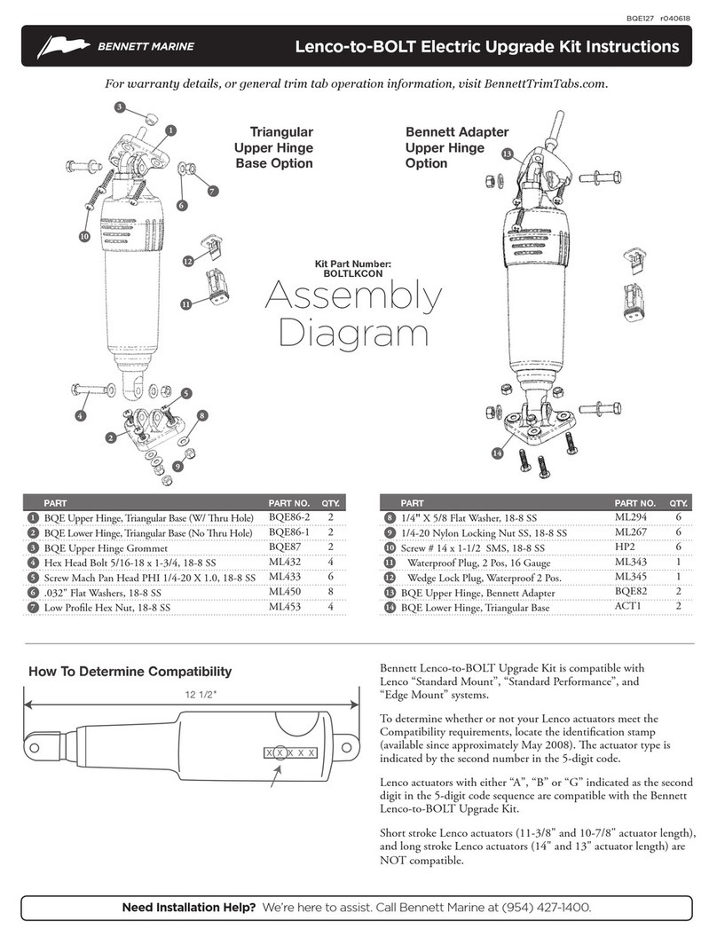
Bennett Marine
Bennett Marine Lenco-to-BOLT instructions
Alamarin Jet
Alamarin Jet AJ 340 Operation and maintenance manual
Japan Radio Co.
Japan Radio Co. RADAR1000MK II Field service manual
LXNAV
LXNAV SmartShunt 100A installation manual
Lewmar
Lewmar Pro Series Owners installation, operation & basic servicing manual
auer
auer AS1 manual

Raytheon Anschütz
Raytheon Anschütz ECDIS NX Compact System manual
Kongsberg
Kongsberg EA640 installation manual
Volvo Penta
Volvo Penta IPS Installation and System Connections
GST
GST C-9403 quick start guide
