Bennett Marine Lenco-to-BOLT User manual

13
14
Lenco-to-BOLT Electric Upgrade Kit Instructions
BQE127 r040618
Need Installation Help? We’re here to assist. Call Bennett Marine at (954) 427-1400.
1
2
3
4
5
6
7
8
9
10
11
12
PART PART NO. QTY.
1BQE Upper Hinge, Triangular Base (W/ ru Hole) BQE86-2 2
2BQE Lower Hinge, Triangular Base (No ru Hole) BQE86-1 2
3BQE Upper Hinge Grommet BQE87 2
4Hex Head Bolt 5/16-18 x 1-3/4, 18-8 SS ML432 4
5Screw Mach Pan Head PHI 1/4-20 X 1.0, 18-8 SS ML433 6
6.032" Flat Washers, 18-8 SS ML450 8
7Low Prole Hex Nut, 18-8 SS ML453 4
PART PART NO. QTY.
81/4"X 5/8 Flat Washer, 18-8 SS ML294 6
91/4-20 Nylon Locking Nut SS, 18-8 SS ML267 6
10 Screw # 14 x 1-1/2 SMS, 18-8 SS HP2 6
11 Waterproof Plug, 2 Pos, 16 Gauge ML343 1
12 Wedge Lock Plug, Waterproof 2 Pos. ML345 1
13 BQE Upper Hinge, Bennett Adapter BQE82 2
14 BQE Lower Hinge, Triangular Base ACT1 2
For warranty details, or general trim tab operation information, visit BennettTrimTabs.com.
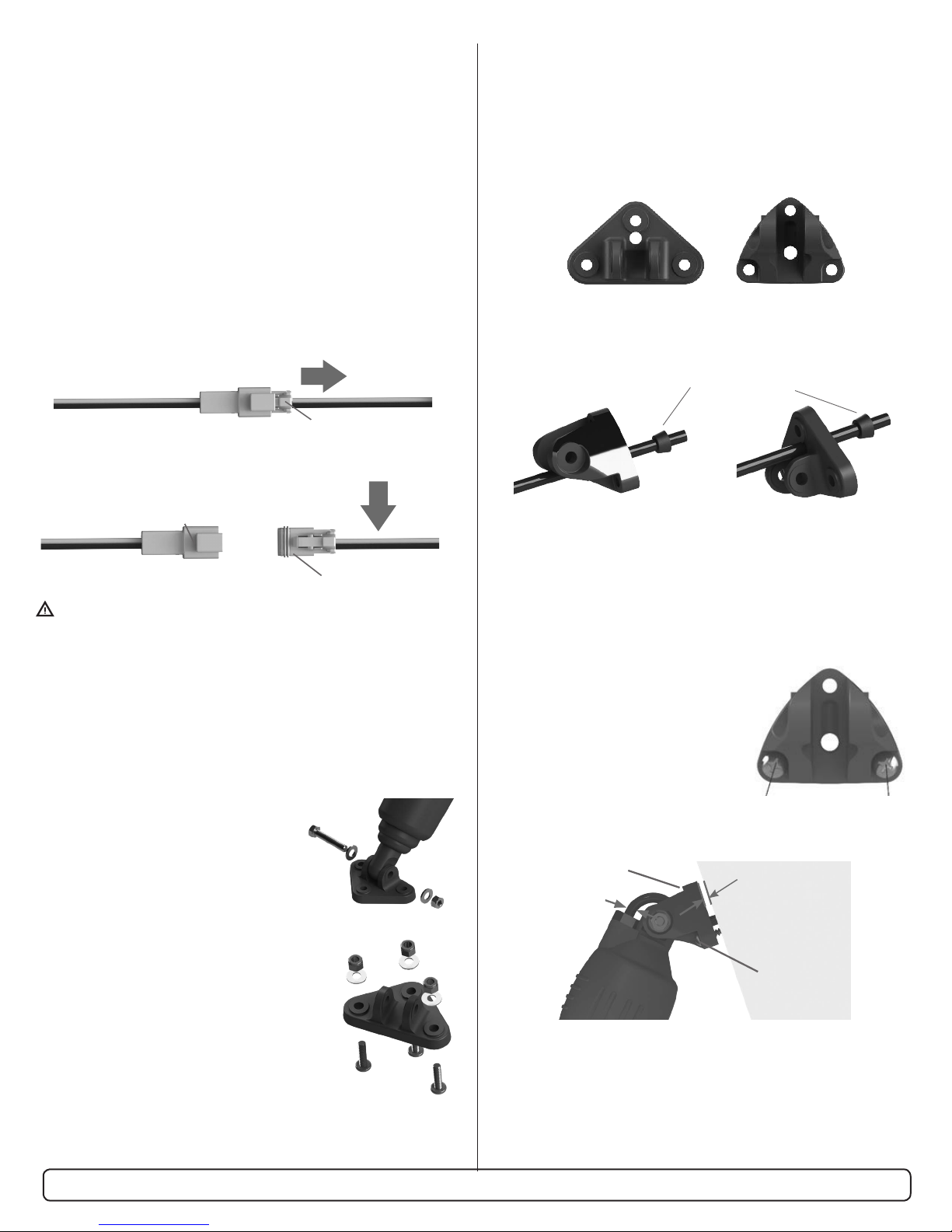
Triangular
Upper Hinge
Base Option
How To Determine Compatibility
Assembly
Diagram
Kit Part Number:
BOLTLKCON
12 1/2"
XXXXX
Bennett Lenco-to-BOLT Upgrade Kit is compatible with
Lenco “Standard Mount”, “Standard Performance”, and
“Edge Mount” systems.
To determine whether or not your Lenco actuators meet the
Compatibility requirements, locate the identication stamp
(available since approximately May 2008). e actuator type is
indicated by the second number in the 5-digit code.
Lenco actuators with either “A”, “B” or “G” indicated as the second
digit in the 5-digit code sequence are compatible with the Bennett
Lenco-to-BOLT Upgrade Kit.
Short stroke Lenco actuators (11-3/8" and 10-7/8" actuator length),
and long stroke Lenco actuators (14" and 13" actuator length) are
NOT compatible.
Bennett Adapter
Upper Hinge
Option
Before Installation
e actuator replacement must be done when the vessel is out of the
water. Do not attempt to replace the actuators while the vessel is in
the water as the actuators are mounted below the water line.
Before performing any electrical work on a vessel, disconnect the
battery by removing the positive (+) cable or if equipped, turning
the battery disconnect switch to the OFF position.
Installation of Adjustable Upper Hinge (BEA3000)
To Remove an Existing LENCO Actuator
• Unplug the wiring harness connection from the actuator to the
relay control module.
• Cut o the wiring harness connector from the actuator cable so it
can pass though the transom hole.
Only cut the wires coming from the actuator.
• Unbolt the lower hinge mount from the Lenco actuator by
removing the 5/16-18 lock nut and bolt using a 1/2" wrench.
• Unscrew the lower hinge mount of the Lenco actuator from
the trim tab by removing the (3) 1/4-20 x 1" long Phillips head
screws and nuts using a #3 Phillips head screw driver and a 7/16"
wrench.
• Clean the tab of any paint and/or barnacles.
• Allow the Trim Tab to swing down and out of the way.
• Unbolt the Lenco actuator from the
adjustable upper hinge by removing the
5/16-18 lock nut and bolt using a 1/2"
wrench. (Figure 1)
• Allow the Lenco actuator to hang
by the wire.
• Unscrew the upper hinge mount of the
Lenco actuator from the transom by removing
the (3) #14 x 1-1/2" long screws using a #3
Phillips head screw driver. (Figure 2)
• e actuator can then be removed. Take care
to gently pull the electrical wires though the
transom hole.
• Clean the hull using a sharp blade to remove
any old sealant from the actuator mounting
locations. Wipe clean using a solvent.
To Remove an Existing LENCO Actuator
• e supplied kit contains 2 dierent upper hinge mounting
options. Compare the new upper hinges to the old LENCO upper
hinge and use the upper hinge that matches the bolt pattern of the
old actuator. Disregard the other pair of upper hinge mounts as
they will not be used.
• Carefully insert the end of the electrical cable though the
adjustable upper hinge mount and install the sealing grommet
onto the cable.
• Pull the cable through the mount until the mount is about 8"
from the actuator.
• Insert the end of the cable through the transom hole.
• Temporarily mount the actuator to the adjustable upper hinge
using the supplied 5/16-18 bolt and lock nut (using a 1/2"
wrench) to set the cable length.
• Temporarily mount the upper hinge
of the new actuator to the transom
using (2) of the supplied #14 x 1-1/2"
screws in the lower mounting
positions, leaving a gap of 1/4"
between the upper hinge and the
transom. Pull the excess cable though
the transom leaving enough cable to
prevent the actuator from binding
during its normal movement.
• Ensure that the cable sealing grommet is moved down the cable to
its seat on the upper hinge.
Press
Actuator Connector
Control Connector
Cut Here
Figure 1
Figure 2
Lower Mounting Positions
No screw for top hole
#14 x 1-1/2" screws
1/4" gap
Allow slack
Need Installation Help? We’re here to assist. Call Bennett Marine at (954) 427-1400.
Compatible
with Lenco
hole pattern
Compatible
with Bennett
hole pattern
Grommet with
small end toward
the upper hinge
mount
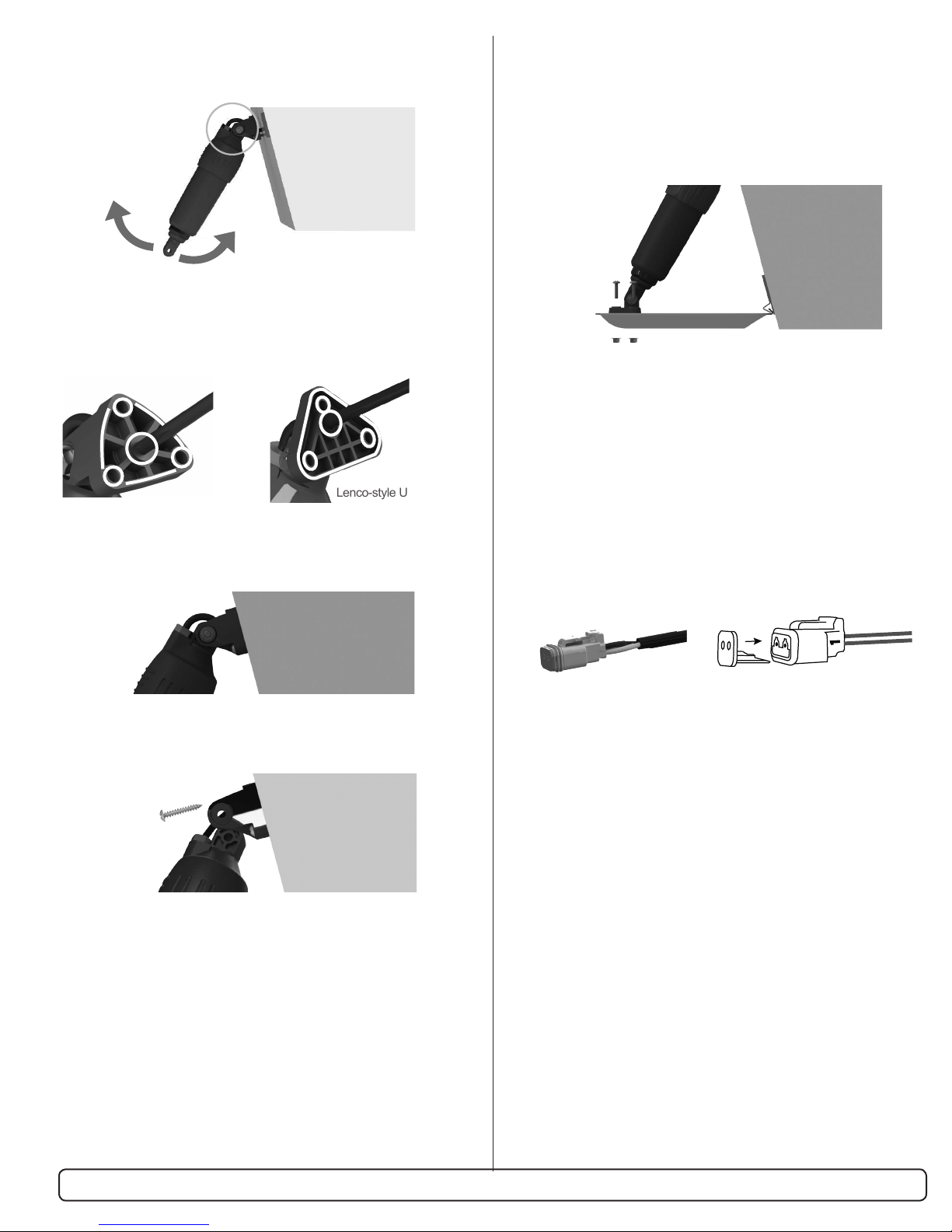
• Swing the actuator through its maximum range of motion to
ensure there is the proper amount of cable to allow movement
without binding.
• Unscrew the two #14 x 1-1/2" screws holding the adjustable
upper hinge and pull back from the transom making sure the
cable length does not change.
• Apply 3M 5200 waterproof sealant on the mounting surface and
around the wiring of the new actuator.
• Screw the adjustable upper hinge to the transom using (2) of the
supplied #14 x 1-1/2" screws in the lower 2 mounting positions.
• Remove the BOLT actuator from the upper hinge allow the
actuator hang.
• Install the remaining (1) #14 x 1-1/2" screw into the top position
of the hinge.
• Install the BOLT actuator to the upper hinge using the supplied
5/16-18 bolt and nut. Make sure not to over-tighten as the
actuator needs to rotate within the hinge.
• Over-tightening will cause the actuator to bind. Do not collapse
upper hinge mount uprights.
• Tighten until the bolt and nut contact the anges of the upper
hinge. ere should be a gap between the uprights of the upper
hinge mount and the anges on the actuator.
• Install the lower hinge mount to the BOLT actuator using the
supplied 5/16-18 bolt, washers, and lock nut. Do not to over
tighten as the actuator.
• Install the lower hinge mount to the trim tab using the (3)
supplied 1/4-20 x 1" screws and nuts using a 1/2" wrench.
• Install the wiring connector onto the wires:
»Insert the white wire into location pin #1, insert the black wire
into location pin #2 into the back of the connector until the
pin locks into place.
»Ensure the proper wire color is on the correct side of the
connector by comparing the old connector that was cut off.
»Install the orange plastic wedge retainer into the front of the
connector.
• Note: Older Lenco systems may not have a waterproof connector.
If your system does not have waterproof connectors, cut the
crimped sockets o the actuator wires and connect using heat
shrinkable butt splices (not splices).
• Connect the male wiring connector to female wiring connector
coming from the relay module. For help with connectors visit
BennettTrimTabs.com/ConnectorHelp.
• Reconnect the positive (+) battery cable or turn battery disconnect
switch to the ON position and check the system for functionality.
• If the actuators are working backwards, the wires are reversed.
Refer to the troubleshooting section on the reverse page.
Bennett Upper Hinge Lenco-style Upper Hinge
Need Installation Help? We’re here to assist. Call Bennett Marine at (954) 427-1400.
Blue (#1)
Yellow (#2)
White (#1)
Black (#2)

Troubleshooting
• Symptom: Actuators work reverse.
»Wires installed backwards. Remove wires from connectors
and reverse.
»For help with connectors visit BennettTrimTabs.com/
ConnectorHelp.
• Symptom: Actuator not working at all.
»Check fuse
»Check output of switch or control using a volt meter.
Connect meter leads to wire harness leads and press control
or switch.
»Caution: Do not allow wire harness leads to touch as
control is pressed or a short circuit will occur.
»Switch meter should show (+)12VDC or (-)12VDC. If
there is no output from the controls, the Lenco controls are
defective. Call Bennett Marine for replacement options or
visit BennettTrimTabs.com.
BennettTrimTabs.com
Need Installation Help?
We’re here to assist.
Call Bennett Marine at (954) 427-1400.
For warranty details, or general trim tab operation information, visit BennettTrimTabs.com.
Other Bennett Marine Marine Equipment manuals

Bennett Marine
Bennett Marine BOLT Instruction Manual

Bennett Marine
Bennett Marine BOLT129 Operation manual

Bennett Marine
Bennett Marine AutoTrimPro Operation manual

Bennett Marine
Bennett Marine SLT6 Operating instructions

Bennett Marine
Bennett Marine AUTO TAB CONTROL Original instructions

Bennett Marine
Bennett Marine ES2000 User manual

Bennett Marine
Bennett Marine BOLT User manual


