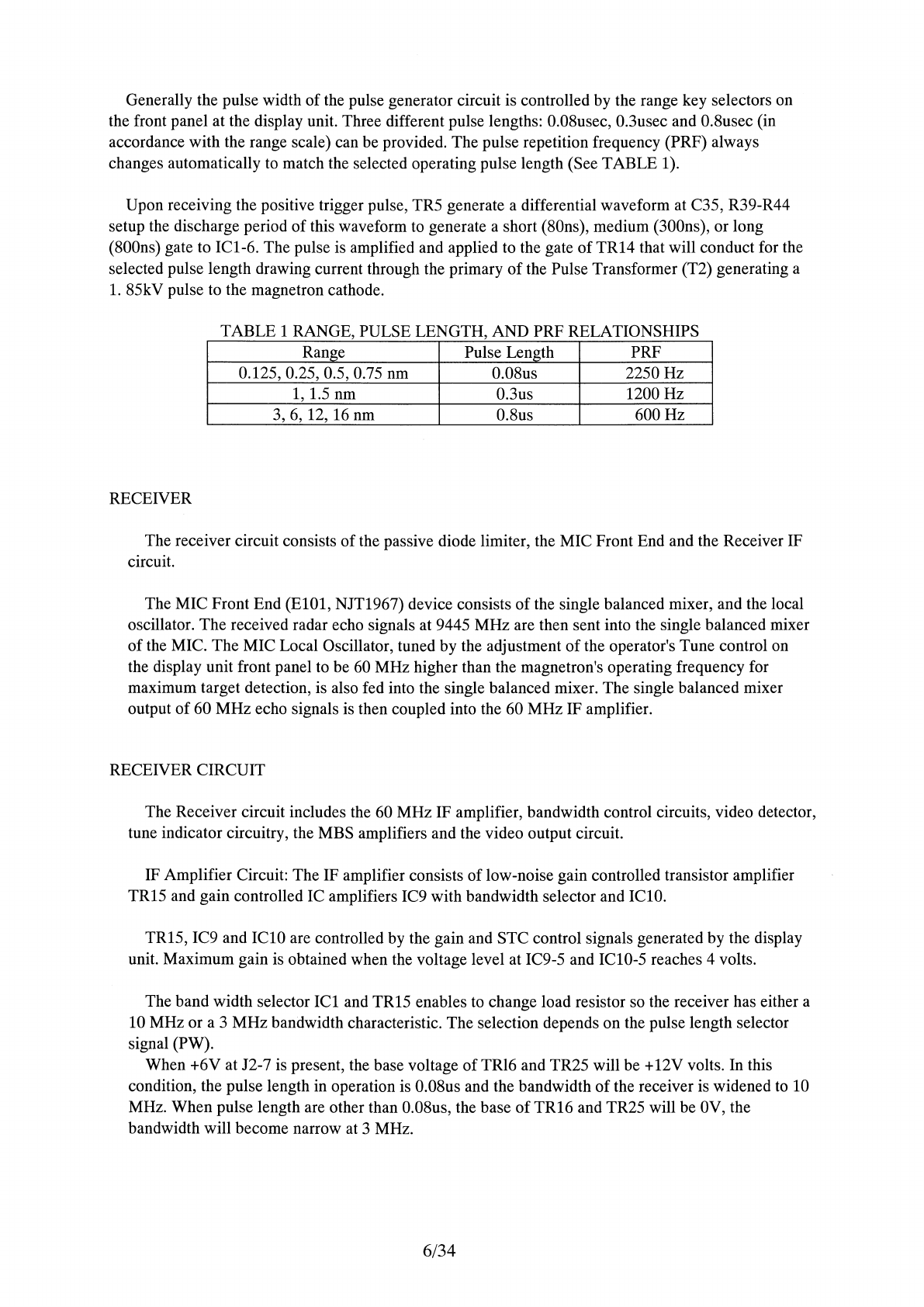
Generally the pulse width of the pulse generator circuit is controlled by the range key selectors on
the front panel at the display unit. Three different pulse lengths: 0.08usec, 0.3usec and 0.8usec (in
accordance with the range scale) can be provided. The pulse repetition frequency (PRF) always
changes automatically
to
match the selected operating pulse length (See TABLE 1
).
Upon receiving the positive trigger pulse, TR5 generate a differential waveform at C35, R39-R44
setup the discharge period of this waveform
to
generate a short (80ns), medium (300ns), or long
(800ns) gate to ICl-6. The pulse is amplified and applied to the gate
of
TR14 that will conduct for the
selected pulse length drawing current through the primary
of
the Pulse Transformer (T2) generating a
1.
85kV pulse to the magnetron cathode.
TABLE 1 RANGE, PULSE LENGTH, AND PRF RELATIONSHIPS
Range Pulse Length PRF
0.125, 0.25, 0.5, 0.75 nm 0.08us 2250 Hz
1,
1.5 nm 0.3us 1200 Hz
3,
6,
12, 16 nm 0.8us
600Hz
RECEIVER
The receiver circuit consists of the passive diode limiter, the MIC Front End and the Receiver IF
circuit.
The MIC Front End
(ElOl,
NJT1967) device consists
of
the single balanced mixer, and the local
oscillator. The received radar echo signals at 9445 MHz are then sent into the single balanced mixer
of the MIC. The MIC Local Oscillator, tuned by the adjustment of the operator's Tune control on
the display unit front panel to be
60
MHz higher than the magnetron's operating frequency for
maximum target detection, is also fed into the single balanced mixer. The single balanced mixer
output
of
60 MHz echo signals is then coupled into the 60 MHz IF amplifier.
RECEIVER CIRCUIT
The Receiver circuit includes the 60 MHz IF amplifier, bandwidth control circuits, video detector,
tune indicator circuitry, the MBS amplifiers and the video output circuit.
IF Amplifier Circuit: The IF amplifier consists oflow-noise gain controlled transistor amplifier
TR15 and gain controlled IC amplifiers IC9 with bandwidth selector and IClO.
TR15, IC9 and IClO are controlled by the gain and STC control signals generated by the display
unit. Maximum gain is obtained when the voltage level at IC9-5 and ICl0-5 reaches 4 volts.
The band width selector
ICl
and TR15 enables
to
change load resistor so the receiver has either a
10 MHz or a 3 MHz bandwidth characteristic. The selection depends on the pulse length selector
signal (PW).
When +6V at J2-7 is present, the base voltage of
TR16
and TR25 will be +12V volts. In this
condition, the pulse length in operation is 0.08us and the bandwidth
of
the receiver is widened
to
10
MHz. When pulse length are other than 0.08us, the base
of
TR16 and TR25 will be 0V, the
bandwidth will become narrow at 3 MHz.
6/34