Sekotech ST-300 SPIDER User manual

S
T-300
S
P
IDER
LINE AND MAINS ANALYZER
OPERATING MANUAL


OPERATING MANUAL
1
CONTENTS Pg
Introduction 3
1. General Information on ST300 “SPIDER” 3
1.1. Purpose and Main Features 3
1.2. Packing and Kit 4
1.2.1. Packing 4
1.2.2. Supply Kit 5
1.3 Design 6
1.3.1. Main Unit 6
1.3.2. Electronic Switch 7
1.3.3. Connecting the Electronic Switch to the Main Unit 8
1.3.4. Receiver of the Cable Locator 8
1.3.5. Adaptor for Testing Power Mains 10
1.3.6. Test sound player 11
2. Operation Modes of ST300 12
2.1. Startup 12
2.2. Start Menu (Mode Selection Menu) 12
2.3. Settings 13
2.3.1. Date Setup 13
2.3.2. Time Setup 14
2.3.3. Interface Language Setup 14
2.4. Electronic Switch Control Mode (“SWITCH”) 14
2.4.1. Main Screen of the “SWITCH” Mode 14
2.4.1.1. Selecting a Wire Pair 15
2.4.1.2. Display of Wire Pair Selection 15
2.4.1.3. Display of Voltage in the Selected Wire Pair 15
2.4.1.4. Switching to Other Modes 15
2.4.2. Additional Modes 15
2.4.2.1. Automatic Measurement Mode 15
2.4.2.2. “CABLE LOCATOR” Mode 16
2.5. “LOW FREQUENCY AMPLIFIER” Mode 17
2.5.1. Main Screen of the “LFA” Mode 17
2.5.1.1. Cable Settings 18
2.5.1.2. Gain Control 19
2.5.1.3. Setting a Bias Voltage 19
2.5.1.4. Switching to Other Modes 20
2.5.2. Automatic Mode of the LF Amplier 20
2.6. “WIRED RECEIVER” Mode 21
2.6.1. Main Screen of the “WIRED RECEIVER” Mode 21
2.6.2. Differential Wired Receiver Mode 22
2.6.3. Monitoring Signal at a Set Frequency 23
2.6.4. “OSCILLOSCOPE” Mode 24
2.6.5. Automatic Mode of the Wired Receiver 24
2.7. “NONLINEAR JUNCTION DETECTOR” Mode 25
2.7.1. Main Screen of the “NLJD” Mode 26
2.7.1.1. Cable Settings 26
2.7.2. Automatic Mode of the Nonlinear Junction Detector 26
2.7.2.1. Cable Settings 27

ST300 SPIDER
2
CONTENTS Pg
2.7.1.2. Automatic Scanning 27
2.8. “REFLECTОMETER” Mode 27
2.8.1. Main Screen of the “REF” Mode 28
2.8.1.1. Setting the Velocity Factor 29
2.8.1.2. Cable Settings 29
2.8.1.3. Measurements in the Main Screen 29
2.8.2. Automatic Reectometer Mode 30
3. Basic Search Routines with ST300 32
3.1. Physical Connection to the Tested Line 32
3.2. Electronic Connection to the Tested Line 37
3.3. Search for Low-Frequency Transmissions in Low-Current Lines 40
3.3.1. Search for Low-Frequency Transmissions: Manual “LFA” Mode 40
3.3.2. Search for Low-Frequency Transmissions: Automatic “LFA” Mode 42
3.4. Search for High-Frequency Transmissions in Cabling 44
3.4.1. Search for High-Frequency Transmissions in Power Mains 44
3.4.2. Search for High-Frequency Transmissions in Low-Current Lines 46
3.5. Nonlinearity Detection in Cabling 47
3.5.1. Nonlinear Junction Detector of ST300 in Use: Manual Mode 78
3.5.2. Nonlinear Junction Detector of ST300 in Use: Automatic Mode 79
3.6. Anomaly Detection in a Cable 50
3.6.1. Reection Meter of ST300 in Use: Cable Testing from both Ends 51
3.6.2. Reection Meter of ST300 in Use: Automatic Mode 52
3.7. Cable Tracing 55
3.7.1. Cable Locator of ST300 in Use: Non-Contact Search 55
3.7.2. Cable Locator of ST300 in Use: Contact Search 56
3.8. Locating a Detected Bugging Device 57
3.8.1. Locating a Detected Bugging Device with Test Sound 57
3.8.2. Locating a Detected Bugging Device with ST300 and a Nonlinear Junction Detector 58
4. Power Supply and Battery Charging 59
5. Technical Specications of ST300 60
6. Reference Information 62
6.1 Twisted Pair Cabling 62
6.2 RJ Standards 62
6.3 Wiring Scheme of a 4 Twisted-Pair Cable 62
6.4 Wiring Scheme of a 3, 2, and 1 Twisted-Pair Cable 64
6.5 Reference Information on Telephone Lines 64

OPERATING MANUAL
3
INTRODUCTION
This manual explains the operating principles, design, and functioning of the ST300 “SPIDER”Line
Analyzer, please study it carefully before using the device.
Please connect any cabling, adaptors and/or auxiliary equipment to the device, observing the
procedures and order as described in the applicable sections of this manual. For connection to power
mains, please only use standard cables and adaptors supplied with ST300.
Please bear in mind that only properly trained and certied personnel may test power mains.
1. GENERAL INFORMATION ON ST300 “SPIDER”
1.1. PURPOSE AND MAIN FEATURES
Purpose
The ST300 “SPIDER”Line Analyzer is designed to detect and locate eavesdropping devices directly
(galvanically) connected to power electric lines and low-current circuits. It employs both passive and
active methods, which allows detecting eavesdropping devices that are active at the time of the sweep,
as well as those that are “silent”.
Main Features
ST300 “SPIDER” implements an essential set of features required for detecting and locating wire-
connected eavesdropping electronics. Its capabilities include:
• the detection and estimation of signals from hard-wired microphones in low-voltage lines;
• forced activation of electret microphones by applying a bias voltage;
• detection of cable transmissions from eavesdropping devices in the frequency range from 100kHz
to 150MHz;
• detection and estimation of unsolicited electric (galvanic) connections to cabling, in the modes of a
nonlinear junction detector and a reection meter;
• tracing the cabling in walls and other structures;
• testing multiple conductor cables with the aid of an electronic switch;
• measuring AC and DC voltages.
The device can be used on its own, or controlled from a computer utilizing special software.
WARNING! In all modes of operation, ST300 may only be powered from its internal power source
(inbuilt battery)!

4
ST300 SPIDER
1.2. PACKING AND KIT
ST300 comes in a kit that serves all of the above-named research tasks and makes the device multi-
purpose, its operation autonomous, and its transportation and storage safe and convenient.
1.2.1. Packing
ST300 is a portable device. It is carried and stored in a NANUK-915 shock- and moisture-proof plastic
case. For the safety of transportation and storage, and the convenience of use, a three-layered packing
scheme is employed, shown in Fig. 1.
Fig.1

OPERATING MANUAL
5
1.2.2. Supply Kit
The Supply Kit that comes with ST300 includes:
1 – USB cable for connecting ST300 to a laptop ..................................................................1 pc.
2 – cable for telephone junction-box testing........................................................................1 pc.
3 – cable for connecting the electronic switch to RJ45 sockets ...............................................1 pc.
4 – cable for connecting the electronic switch to twin wire low voltage lines.............................1 pc.
5 – probe for the cable locator receiver...............................................................................1 pc.
6 – cable for testing power mains equipped with electric sockets............................................1 pc.
7 – tester screwdriver ......................................................................................................1 pc.
8 – cable for connecting the electronic switch to telephone sockets.........................................1 pc.
9 – charger.....................................................................................................................1 pc.
10 – ST300 main unit ......................................................................................................1 pc.
11 – ashcard with software and documentation..................................................................1 pc.
12 – crocodile clamp .......................................................................................................2 pcs.
13 – mains adaptor .........................................................................................................1 pc.
14 – cable for the test sound player....................................................................................1 pc.
15 – test sound player......................................................................................................1 pc.
16 – electronic switch ......................................................................................................1 pc.
17 – receiver of the cable locator ......................................................................................1 pc.
18 – accumulator batteries for the cable locator receiver (ААА).............................................2 pcs.
19 – headphones.............................................................................................................1 pc.
20 – pass-through socket (RJ45)........................................................................................1 pc.
21 – splitter (RJ45)..........................................................................................................1 pc.
22 – splitter (RJ12)..........................................................................................................1 pc.
23 – short-circuiter socket (RJ45).......................................................................................1 pc.
24 – telescopic arm of the cable locator receiver...................................................................1 pc.
25 – multiwire cable connector (with a screwdriver) ..............................................................1 pc.
26 – ground connection cable.............................................................................................1 pc.
27 – device passport.........................................................................................................1 pc.
28 – protective case with custom panels..............................................................................1 pc.
In Fig. 1, items supplied with ST300 are assigned the same numbers as in the following subsection
(1.2.2) of this manual. Each item has its own position in the case; in order to avoid mechanical damage
of the Main Unit and its accessories, please place them according to the manufacturer’s layout.

ST300 SPIDER
6
1.3 DESIGN
1.3.1 Main Unit
The appearance, connectors, control and display elements, as well as mechanical parts of the Main
Unit, are shown in Fig. 2.
Fig.2
# in g. 2 subscript
on the unit purpose
1color display for graphic data output
2keyboard
F1-F4 hotkeys whose assignment changes depending on the mode (and is
shown on display)
ESC cancel / return to previous mode
FUNC additional functions
ENTER conrm mode selection / conrm action
MODE automatic mode on/off

OPERATING MANUAL
7
# in g. 2 subscript
on the unit purpose
3PWR external power indicator
4ON/OFF
VOLUME
power switch / volume control
5USB USB port for laptop connection
6PHONE headphone socket
7DC5V charger socket
8universal input connector
9slot for the Electronic Switch
10 info shield
1.3.2 Electronic Switch
The Electronic Switch is used for testing multiple-wire low-voltage cables. It is controlled from the
Main Unit of ST300.
The appearance, connectors, control and display elements, as well as mechanical parts of the Electronic
Switch, are shown in Fig. 3.
Fig.3
# in g. 3 purpose
1cable for connection to the main unit
2bracket for attachment to the main unit
3socket for cable with RJ45 connector
4lever for attachment to the main unit

ST300 SPIDER
8
Рис. 7
1.3.3 Connecting the Electronic Switch to the ST300
Main Unit
The Electronic Switch is attached to the Main Unit
with the aid of a T-slot & lock mechanism, parts of which
are located on the body of the Main Unit, and on the
Electronic Switch. The two units are locked together by
rotating the lever.
The sequence of actions for joining the Electronic
Switch with the Main Unit is shown in Fig. 4.
1. Insert the guide of the Electronic Switch into the
T-slot on the Main Unit, with the lock arm in the vertical
(“open”) position. In the direction shown in the picture,
slide the guide all the way through the slot (Fig. 4, step
1).
2. Rotate the lock lever all the way (Fig. 4, step 2).
3. Insert the Electronic Switch connector into the
universal socket of the Main Unit (Fig. 4, step 3). Tighten
the connector nut without applying extra force.
Step 4 in Fig. 4 portrays the Main Unit correctly joined
with the Electronic Switch.
To disconnect and detach the Electronic Switch,
proceed in the reverse sequence.
Caution! Connect (disconnect) the Electronic
Switch only while the Main Unit is turned off!
1.3.4 Receiver of the Cable Locator
The Receiver unit is a functionally complete device and has power supply of its own (two 1.5V “ААА”
batteries). On the front panel of the unit are control and display elements, and a socket for the contact
probe. On the back is the battery compartment lid. The unit has a speaker for sound notications. The
appearance of the Receiver and the locations of its control and display elements are shown in Fig. 5.
Fig.4

OPERATING MANUAL
9
Fig.5
# in g. 5 Sign on Unit purpose
1socket for the probe or telescopic arm plug (for contact testing)
2PWR power on/off;
sound on/off
3SIGNAL test signal reception indicator (red LED)
4
LED indicator bar showing the receiver sensitivity (minimum/medium/
maximum) or indicating critically low battery, with all the three LEDs
blinking
5GAIN sensitivity control
6battery compartment lid
When the Receiver is used in a non-contact search, it is recommendable to use the telescopic arm
supplied with ST300. This will, rstly, prevent the user’s body capacitance affecting the receiver, and
secondly, make it easier to explore the upper walls and ceiling.
The arm consists of a telescopic handle and bracket-and-clamp assembly. The telescopic arm is shown
in Fig. 6.
Fig.6
The numbers in Fig. 6 represent:
1 - hold-down bar
2 - bracket
3 - cable with a pin connector
4 - screw connecting the bracket to the
telescopic arm
5 - screw that xes the position (incline) of the
bracket
6 - telescopic handle
To mount the Receiver onto the telescopic arm
and prepare it for operation, pull up the hold-down
bar 1, place the Receiver as shown in Fig. 7 and
release the hold-down bar.
Plug the pin connector 3 into the corresponding
socket of the Main Unit (1, Fig.5).

ST300 SPIDER
10
Fig.7
1.3.5 Adaptor for Testing Power Mains
The Mains Adaptor, shown in Fig. 8, is used to connect ST300 to
lines with voltages over 100V.
The numbers in Fig. 8 represent:
1 – mains cable socket
2 – LED indicators of in the line being tested (two lit LEDs for AC,
one lit LED for DC)
3 – connector for plugging into the Main Unit
For the connection of the Adaptor to a tested line, two mains
cables are supplied with ST300. To connect through a standard
electric outlet, please use the cable with a plug (1, Fig.9). For
testing through a distribution box (contactor panel), please use the
one with clamps (2, 3, Fig.9).
Fig.8
Fig.9

OPERATING MANUAL
11
1.3.6 Test sound player
The Test sound player is used for:
• the emission of a known acoustic signal on site (if the sound response from ST300 correlates
with the test sound, that means there is an active eavesdropping device around that sends uncoded
transmissions);
• forced triggering of voice-activated eavesdropping electronics equipped with VOX;
• locating the detected eavesdropping electronics;
• emission of a masking noise during searches;
• playback from external devices connected via line input.
For these purposes, an MP3 player is supplied with ST300. Using a ash card, the operator may
record and play custom signals that are best tailored to his search procedures.
Fig.10 shows the ports and controls of the Test Sound Player:
1 – speaker
2 – power indic ator
3 – previous le playback
4 – next le playback
5 and 6 – volume control
7 – “PLay/Pause/Stop”
8 – power switch
9 – headphone socket
10 – line input / charger
11 – microSD slot
audio le playback:
Copy all the necessary les with test and masking signals to a microSD card.
Insert the microSD card into the microSD slot (11, Fig.10).
Turn on the MP3 player (8, Fig.10); the power indicator (2, Fig.10) will go on.
using the line input
This can be used for audio playback from ST300. It can also serve for establishing a sound loop with
hidden microphones (Larssen effect).
Extract the microSD card from the port (11, Fig.10).
Turn off power (8, Fig.10).
Connect the Test Sound Player to the “PHONE” socket with Cable (6, Fig.2).
Adjust the volume level with buttons (5-6, Fig.10).
charging
The accumulator incorporated in the Test Sound Source is chargeable from a USB-port of a computer
through a USB/mini-USB cable.
Connect the miniUSB end of the cable to the Player (10, Fig.10), and the USB end to a computer. If
the power switch is in the “OFF” position, the indicator (2, Fig.10) will be shining red while the battery
is being charged. The player can also be charged while turned on, with the indicator (2, Fig.10) shining
blue; however, the charging time will increase.
Fig.10
ST300 SPIDER
12
2. OPERATION MODES OF ST300
For tackling the various tasks of detecting and locating eavesdropping electronics, ST300 “SPIDER”
packs versatile features, both active and passive, and is supplied with a variety of accessories answering
these needs.
It is designed and programmed to function in the following modes:
– electronic switch;
– low-frequency amplier;
– wired receiver;
– wired nonlinear junction detector;
– reection meter;
– cable locator.
All of these modes are user-activated. ST300 can only operate in one of the main modes at a time.
2.1 STARTUP
Fig.11
The Main Unit of ST300 is turned on and off with the “ON/OFF
VOLUME” switch on its right side (4, Fig.2).
Within 1-2 seconds of activation the screen will show:
– manufacturer name and logo;
– name of the device;
– rmware version (Fig.11).
Press any button to go to the Start Menu.
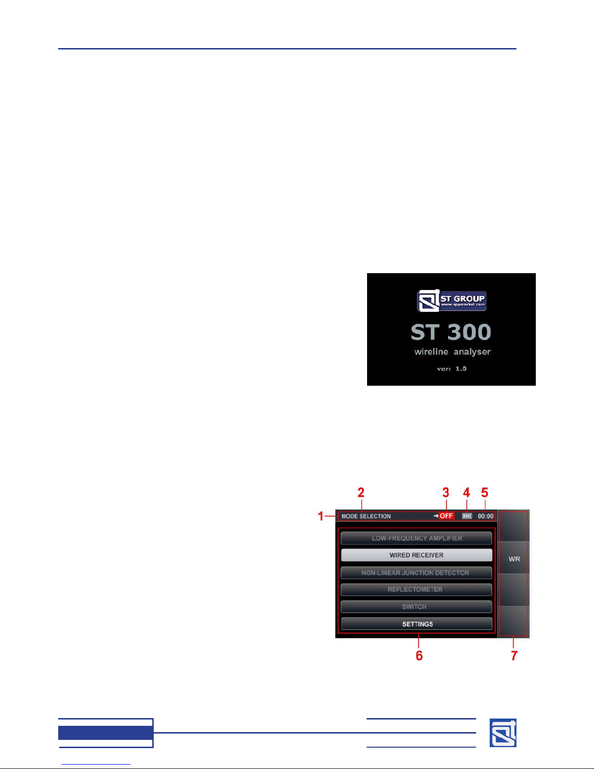
2.2 Start Menu (Mode Selection Menu)
The Start Menu is the point of entry to all the operation modes of ST300.
Attention! If the Electronic Switch is not connected with the Main Unit of ST300, only
“WIRED RECEIVER”and “SETTINGS”modes are available.
The appearance of the Start Menu in the absence of the Electronic Switch is shown in Fig. 12.
Fig.12
The numbers in Fig. 12 represent:
1 – status bar
2 – current mode
3 – indication of the selected wire pair (reading “OFF”
if the Electronic Switch is not connected)
4 – battery status
5 – clock (in “hh-mm”format)
6 – main area of the display (now listing the available
modes)
7 – assignment of hotkeys (if the Electronic Switch is
not connected, only the “WR”key is available that
turns on the “WIRED RECEIVER”mode)
The modes will be shown differently in the main
area (6, Fig.12) depending on whether the Switch is
connected or not.
Fig.13 shows three possible appearances of the same menu item, depending on the presence or
absence of the Electronic Switch, and cursor position:

OPERATING MANUAL
13
Fig.13
1 – mode unavailable (Electronic Switch not
connected)
2 – mode available (Electronic Switch connected)
3 – highlighted by the cursor
Fig.14 shows the Start Menu, with the Electronic
Switch connected to the Main Unit.
The numbers in Fig. 14 match those in Fig.12.
As is seen from the picture, with the Electronic Switch
connected to the Main Unit, all the items in the modes
list (6, Fig. 14) are available, and so are all the hotkeys
(7, Fig 14.).
To select a mode, move the cursor to the corresponding
list item using the and keys, and press “ENTER”.
If the Electronic Switch is connected to the Main
Unit, and hotkeys are active in the Start Menu (7,
Fig.14), use “F1”, “F2”, “F3”and “F4”for quick access
to the modes “LOW FREQUENCY AMPLIFIER”, “WIRED
RECEIVER”, “NONLINEAR JUNCTION DETECTOR”,
and “REFLECTOMETER”, respectively. The keyboard
hotkeys are located to the right of the display, next to
the corresponding hotkey legends on the screen. The
hotkey assignments change depending on the current
mode of operation.
2.3 SETTINGS
The “SETTINGS”mode is always available, regardless
of whether the Electronic Switch is connected to the
Main Unit or not. In this mode, the date, time, and
interface language can be set. To enter the settings,
select the menu item using the vertical arrow keys and
press “ENTER”.
The “SETTINGS”menu is shown in Fig. 15.
Fig.15
2.3.1 Date Setup
Set the date using the and keys.
Move the cursor to the “DATE” eld and press “ENTER”.
The date setting menu will appear on the screen (Fig.16),
with the date shown in the format “DD-MM-YYYY”.
Using the and keys, move the cursor to the “DAY”
eld.
With the and keys, set the required value and
press “ENTER” to conrm. Fig.16
Fig.14

ST300 SPIDER
14
Similarly, set the required values for “MONTH”and “YEAR”. If “ESC” is pressed before conrming the
entered values, they will not be saved, and the device will exit the clock setting mode. All conrmed
values will remain in the device’s memory on exiting the setting menu, and will stay saved even when
the power is switched off.
2.3.2 Time Setup
To set the time, in the “SETTINGS”menu move the cursor to the
“TIME” eld using the and keys, and press “ENTER”.
The time setting menu will appear on the screen (Fig.17), with
time shown in the format “HH-MM”. Time is set in the same
manner as the date (2.3.1). To conrm the selected values,
press “ЕNTER”.
To return to “SETTINGS”, press “ESC”.Fig.17
2.3.3 Interface Language Setup
To set the language, select “LANGUAGE” in the “SETTINGS”menu using the and keys, and
press “ENTER”. The interface language will change from Russian to English. To set Russian, select the
menu item “РУССКИЙ ЯЗЫК”and press “ENTER”.
Upon setting the language in the “SETTINGS”mode, press “ESC”to return to the Start Menu.
2.4 ELECTRONIC SWITCH CONTROL MODE (“SWITCH”)
The “SWITCH”mode is only available when the Electronic Switch is connected to the Main Unit.
This mode is intended for testing low-current lines. It allows running tests over all possible two-wire
combinations in a multiple-wire cable (up to 8 cores, in the current version).
As the “SWITCH”mode is the main one for testing low-current lines, it is readily accessible from the
Start Menu, as well as from “LOW FREQUENCY AMPLIFIER”, “WIRED RECEIVER”, “NONLINEAR JUNCTION
DETECTOR”, and “REFLECTОMETER”modes.
2.4.1. Main Screen of the “SWITCH”Mode
To access the “SWITCH” mode from the Start Menu (Fig.18), using the and keys
highlight “SWITCH”and press “ENTER”. The main menu of this mode will appear on screen
(Fig.18).
Fig.18
The numbers in Fig. 18 represent:
1 – current mode
2 – wire pair connected to the input of the device
3 – wire pair selection
4 – red frame highlighting the current menu item
that can be adjusted
5 – voltage in the selected wire pair (DC and AC)
6 – engaged contacts of the Electronic Switch
connector (RJ45)
7 – hotkey assignments

OPERATING MANUAL
15
2.4.1.1 Selecting a Wire Pair
To connect a wire pair from the screen of the «SWITCH» mode, do the following:
– using the and keys, position the red frame (4 Fig.18) at the left window of the wire pair (3,
Fig.18); then, using the and keys, set a wire number; now the rst wire in the pair is connected;
– using the and keys, position the red frame (4 Fig.18) at the right window of the wire pair
(3, Fig.18); then, using the and keys, set a wire number; now the pair of wires is connected to
the device.
Please bear in mind that the selected numbers cannot be the same.
2.4.1.2 Display of Wire Pair Selection
The numbers of the wires connected to the device are shown on display (2, Fig.18) in all the operation
modes, until another pair of wires is connected to the device. Also, the RJ45 connector is represented
graphically on display (6, Fig.18), with the selected two contacts marked red.
2.4.1.3 Display of Voltage in the Selected Wire Pair
The display shows measurements of the AC and DC voltages in the pair of wires currently connected
to ST300 (5, Fig.18).
If a measured value exceeds 3V, the rmware automatically disables any of the active modes
(“NONLINEAR JUNCTION DETECTOR”, “REFLECTОMETER”) or аpplying a bias voltage in the “LOW
FREQUENCY AMPLIFIER”mode. To enable these features, the line under testing must be de-energized.
2.4.1.4 Switching to Other Modes
Switching to other modes from the main “SWITCH”menu can be performed in two ways:
– by pressing “ESC”to return to the Start Menu and activating the necessary mode as described in
2.2;
– by accessing the desired mode directly from the “SWITCH”mode menu using the hotkeys:
to “LOW-FREQUENCY AMPLIFIER”– by pressing “F1”;
to “WIRED RECEIVER”– by pressing “F2”;
to “NONLINEAR JUNCTION DETECTOR”– by pressing “F3”;
to “REFLECTОMETER”– by pressing “F4”;
to “CABLE LOCATOR”submode – by pressing “FUNC”;
to Automatic Measurement Mode – by pressing “MODE”.
2.4.2 Additional Modes
The “SWITCH”mode has two sub-modes, i.e., “AUTOMATIC MEASUREMENT MODE”and “CABLE
LOCATOR”.
2.4.2.1 Automatic Measurement Mode
This mode is used for automatic measuring of AC and DC voltages on all possible two-wire combinations
of the tested multi-core cable.
To activate this sub-mode from the “SWITCH”mode screen, press “MODE”. The sub-mode menu
(Fig.19) will appear on the screen. In the list of wire pairs, the one selected in the main menu will be
highlighted by default. Voltages on these two wires will be measured, and the results shown in the table.
Measurements on other two-wire combinations will not be performed.
To measure voltages on all the pairs of wires, press «F4» («Scan All»). The full measurement cycle is
a matter of seconds. The measurement results will be shown in the table. If a measurement exceeds 3V,
the corresponding line in the table will be marked red. Once the measurement cycle is complete, and all
the table lines have lled in with values, further measurements will only be performed on the highlighted
pair.

ST300 SPIDER
16
To activate the Cable Locator mode from the
“SWITCH”mode screen, press “FUNC”.
The screen will change to “LOCATOR”(Fig.20), and
the test signal generator will turn on automatically.
In Fig.20 the numbers represent:
1 – current mode
2 – sub-mode
3 – wire selection for the application of a test signal
4 – graphics showing the contact in the RJ45 socket,
to which the test signal will be applied (red
marking)
Fig.20
2.4.2.2 “CABLE LOCATOR”Mode
This mode serves for tracing cables in walls and other building structures, identifying the tested lines
in non-shielded bundles, and nding the junction box contacts to which the line is connected.
Caution! In order to operate ST300 in the cable locator mode, connect its casing to the
ground using Cable (26, Fig.1). To do this, plug the one end with the pin plug into the “PHONE”
socket (6, Fig.2), and attach the other end equipped with a crocodile clamp, to а ground rod,
or grounded casing of any equipment.
This mode is implemented with the aid of a signal generator integrated into ST300 Main Unit, and an
autonomous Receiver (1.3.4). The tested line is to be connected to the Main Unit through the Electronic
Switch. Upon activation of the cable locator mode, a two-tone test signal is applied to the line. With the
aid of the receiver tuned at the test signal frequency, it is possible to trace the cable line behind wall
paneling, dropped ceilings, and in cable trunking, in a non-contact manner (registering the electromagnetic
radiation around the cable created by the test signal). If contacts in a junction box are to be identied, it
is possible to connect the receiver with the tester probe (5, Fig.1) directly to the terminal board.
Fig.19
The gures in Fig. 19 represent:
1 – current mode
2 – wire pair currently connected
3 – wire pair column
4 – DC values column
5 – AC values column
6 – cursor
7 – hotkey assignments
Use the arrow keys to navigate the table; the
number of the selected wire pair is indicated top of
the screen (2, Fig.19). To exit the sub-mode to the
“SWITCH”mode screen, press “MODE”or “ESC”. The
pair of wires highlighted with the cursor before exiting,
will remain selected.
When the automatic measurement mode is activated again, the table will be showing the latest
measurements, and the cursor will be set at the pair of wires selected in the main menu. To start a new
measurement cycle, press “F4”.
Set the wire number using the and keys. The selected wire number will be shown in the
window (3, Fig.20) and in the graphics (4, Fig.20). The selected pair value in the corresponding eld (2,
Fig.19) will not change. To exit the mode to the “SWITCH” screen, press “ESC”. The test signal generator
will stop. All the settings made in the “SWITCH”mode will be saved.

OPERATING MANUAL
17
2.5 “LOW FREQUENCY AMPLIFIER”MODE
The “LOW FREQUENCY AMPLIFIER”(“LFA”) mode is intended for the detection of,
– low-frequency signals from hard-wired eavesdropping electronics connected to low-current lines;
– acousto-electric conversion (“microphone effect”) involving devices that are connected to low current
circuits in the inspected room.
In the “LFA”mode, signals can be monitored:
– by their graphical representation on the screen (oscillogram or spectrogram);
– by sound (through headphones or speaker).
2.5.1. Main Screen of the “LFA”Mode
The “LFA”mode only becomes available upon connecting the Main Unit with the Electronic Switch.
The mode is accessible from the Start Menu (Fig.18), or from the “SWITCH”mode.
To enter the “LFA”mode from the Start Menum, choose “LOW FREQUENCY AMPLIFIER”using the
and keys, and press “ENTER”. In the “LFA”mode, two ways of data representation are
implemented, i.e., oscilloscope (Fig.21) and spectrum analyzer (Fig.22). On entering the “LFA”mode, it
is “OSCILLOSCOPE”(Fig.21) by default. To toggle between the two forms of representation, press “F4”.
A spectrogram will appear on the screen. Fig.
22 shows the spectrum analyzer in the ultra low
frequency mode.
In Fig. 22:
1 – current mode
2 – data representation form
3 – frequency marked by the cursor
4 – hairline cursor
5 – signal amplitude at the selected frequency
6 – spectrum analyzer screen
7 – selected gain value
8 – selected bias voltage
9 – hotkey assignment Fig.22
In Fig. 21:
1 – current mode
2 – data representation form
3 – time scale value (in µs or ms)
4 – measured signal amplitude
5 – vertical scaling of the oscillogram
6 – oscilloscopic screen
7 – selected gain
8 – selected bias voltage
9 – hotkey assignment
The oscillogram can be scaled horizontally with the and keys, and vertically with the
and keys.
To change data representation to “SPECTRUM ANALYZER”, press “F4”.
The displayed spectrogram (Fig.22) does not scale and spans over the whole range (0-25kHz). It can
be navigated by moving the hairline cursor (4, Fig.22) with the and keys. The current frequency
is always shown numerically above the cursor (3, Fig.22).
To change data representation to (“OSCILLOSCOPE”), press “F4”.
Fig.21

ST300 SPIDER
18
2.5.1.1. Cable Settings
Before proceeding with «LFA» mode operations, it is necessary to select
the appropriate wire pair. This can be done either in the «SWITCH» mode
(2.4.1), or in the automated «LFA» mode menu (2.5.2).
If the number of wires has been reduced in the settings, the excluded
contact numbers will remain unavailable for selection until the settings are
changed.
EXAMPLE
A four-wire cable equipped with a 6P4C modular
connector (RJ14/RJ11, see Fig.23) is to be tested. The
cable is connected through an adapter to the 8-contact
(RJ45) socket of the Electronic Switch. In this case,
four contacts of the Electronic Switch input will not be
engaged. By applying the corresponding settings, they
can be eliminated from the testing procedure, which
will reduce the testing time signicantly.
To open the cable setting menu from one of the
above modes, press “FUNC”. The user is offered the
following choice of cable types:
– twisted-pair cable (one, two, three, or four pairs);
– any multiwire cable (up to eight wires in a bundle).
Figs. 24-26 show the cable settings menu.
In Fig. 24, twisted-pair cable settings are shown,
the numbers representing:
1 – twisted-pair cable heading
2 – graphics showing the RJ45 input socket of the
Electronic Switch (with the engaged contacts
marked red and inactive contacts marked black)
3-6 – numbers of twisted pairs in cable, with the
current selection highlighted white.
7 – heading of a straight cable
Fig. 24 represents the connection of a cable
comprising four twisted pairs.
For cable settings, use the following controls:
and keys, for setting the cable type;
and keys, for setting the number of twisted
pairs, or cores in a cable; press “ENTER”, to conrm
selection;
“FUNC”or “ESC”, to exit to the main screen.
Fig.23
Fig.24
Рис.25
Fig.26
Table of contents
Popular Measuring Instrument manuals by other brands

Hanna Instruments
Hanna Instruments Marine Master HI97115 Quick reference guide

Autonics
Autonics KRN1000 Series user manual

Rex Gauge Company
Rex Gauge Company OS-1 Operation manual

YOKOGAWA
YOKOGAWA 701978 user manual

Keysight Technologies
Keysight Technologies N9029AV01-V19 user guide

Bogen
Bogen AKS17 Installation and operating instructions

VWR International
VWR International UV-6300PC instruction manual

Emerson
Emerson Rosemount quick start guide

Keysight
Keysight M9217A PXIe 2-CH Startup guide

SPX
SPX LeakMaster Operator's manual

Optimec
Optimec JCF/F User's manual & operating instructions

Avery Weigh-Tronix
Avery Weigh-Tronix ZM510 Service manual


