SPX LeakMaster User manual
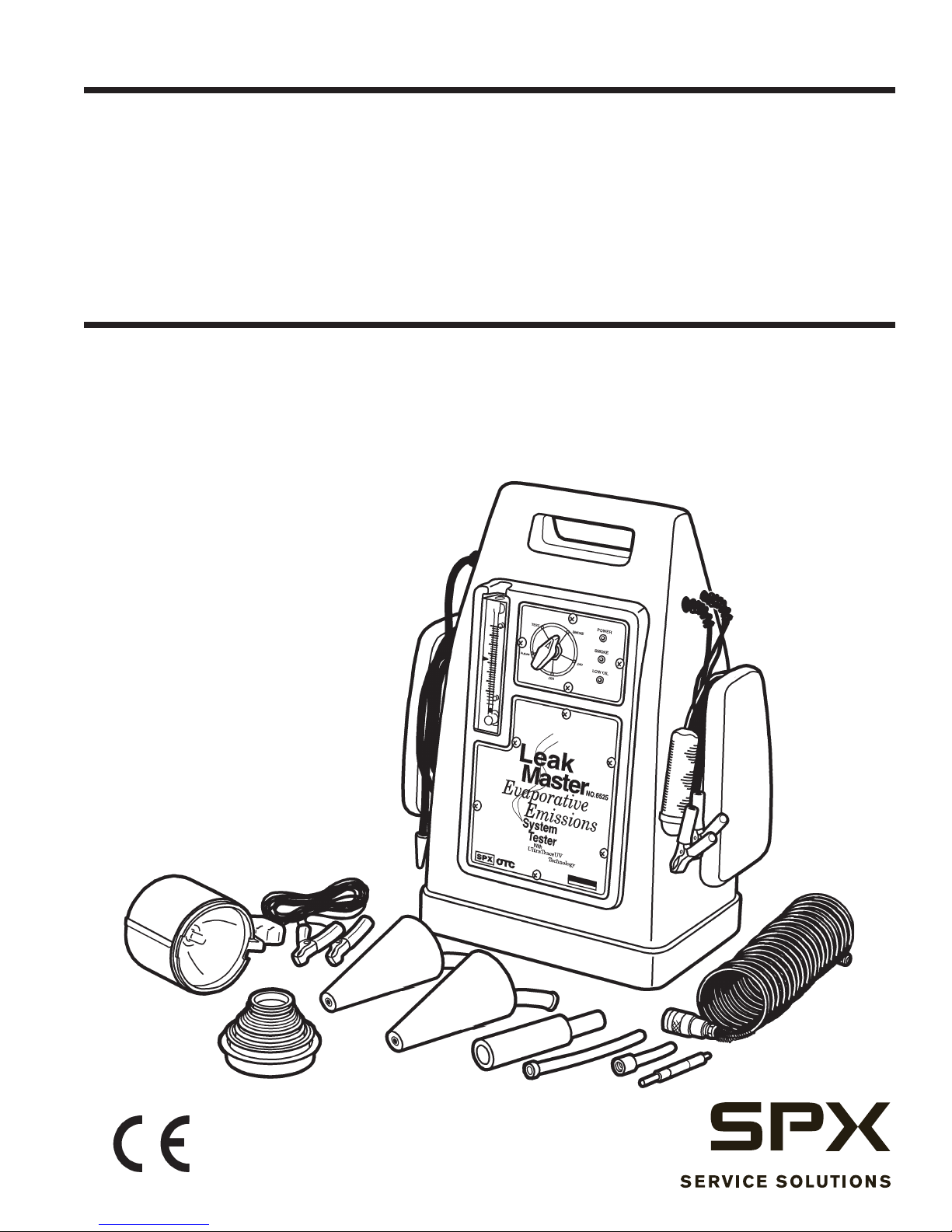
LeakMaster™
Evaporative Emissions System Tester with UltraTraceUV ®dye Technology
Probador del sistema de emisiones de evaporatión y la tecnologia de tinte UltraTraceUV ®
Testeur de système absorbeur de vapeurs de carburant de colorants UltraTraceUV ®technologie
Part No. 6525
Operator’s Manual
Manual del operador
Manuel de l’opérateur

1
Table of Contents
Table of Contents .............................................................................1
Safety Precautions............................................................................2
Background......................................................................................3
Introduction......................................................................................4
Technical Specications...................................................................4
Tester Overview ...............................................................................5
Setup ...............................................................................................6
Phase One.........................................................................................7
Phase Two ........................................................................................9
Vacuum and Induction Leaks.........................................................10
Exhaust Leaks ................................................................................13
Miscellaneous Leaks......................................................................14
Oil Seals and Gasket Leaks.................................................14
Intercooler and Turbocharger Leaks ...................................14
Component Testing .............................................................15
Under-Dash Leaks...............................................................15
Wind and Water Leaks ........................................................16
Maintenance...................................................................................17
Parts List ........................................................................................18
Troubleshooting .............................................................................19
Diagnostic Lights................................................................19
Guide...................................................................................19
Fluid Change Record .....................................................................20
Quick Reference.............................................................................21
Warranty.........................................................................................22
Español...........................................................................................23
French ............................................................................................45
2
If the operator cannot read these instructions, operating instructions and safety
precautions must be read and discussed in the operator’s native language.
WARNING: To prevent personal injury and / or damage to equipment :
• Read, understand, and follow all safety precautions and operating
procedures.
• Do not use this equipment in a manner not specified by the
manufacturer.
• Wear eye protection that meets OSHA standards. If using an optional
ultraviolet light to search for leaks, wear yellow UV goggles that
meet OSHA standards. Never stare directly into a UV light or shine
UV light on skin.
•Because of an evaporative system’s volatile fumes, use an inert
gas, such as nitrogen, when testing an EVAP system.
• Do not perform tests near a source of spark or ignition.
•Correctly connect the power supply to the battery and chassis
ground.
•The spotlight is designed for intermittent use only, not constant
use.
• If the spotlight is hot, do not touch the top part of the lamp or lens,
donotplaceitnearammableitems,anddonotputitawayfor
storage until it cools.
• Do not use the spotlight if it is damaged.
Safety Precautions

3
The fuel vapor recovery system is the most
neglected part of a vehicle’s emission system,
according to the Environmental Protection
Agency (EPA).
The vehicle’s EVAP system is used to collect fuel
vapors from the fuel tank. These vapors are stored in
a canister lled with activated charcoal. The EVAP
system allows the fuel vapors to be drawn from
the canister and combust during certain operating
conditions. This process is called canister purging,
since the fuel vapors are purged from the canister.
OBD-II requires Powertrain Control Module (PCM)
monitoring for correct operation of the EVAP system
and for possible leaks to the atmosphere.
A faulty EVAP system will allow hydrocarbons (HC)
to escape into the atmosphere. Factory emission
tests have determined that an EVAP system
with a leak as small as .020 can yield an
average of 1.35 grams of HC per vehicle-
driven mile. This is over 30 times the current
allowable exhaust emissions standard.
In addition to causing HC emissions, failure of the
EVAP system wastes fuel and many times creates
customer-complaints of “gasoline odors.” With
the introduction of On-Board Diagnostics
(OBD), the automotive industry is capable of
determining if a vehicle’s evaporative system
has a leak. Prior to the LeakMaster No. 6525,
determining the location of an EVAP leak was a
difcult and time-consuming challenge.
LeakMaster Operation
The LeakMaster is a dual-phase tool. Phase One
uses an inert gas, such as nitrogen, to test the integrity
of the vehicle’s fuel vapor recovery system by quickly
determining if, in fact, a leak exists. Phase Two
quickly nds the leak using both visual vapor (smoke)
and UltraTraceUV®dye technology. UltraTraceUV®
is a unique chemical bonded to the smoke that deposits
an ultraviolet ngerprint at the exact location of the
leak.
Background
This dual-phase operation is accomplished
automatically. LeakMaster sets the critical pressure
that must be maintained during EVAP testing. You
don’t need to set ow rates, and you don’t need to be
concerned with ambient temperatures or barometric
pressures.
LeakMaster will not spill its solution regardless of
the position it’s placed in, and is rellable by the end
user when the smoke-producing solution is depleted.
The smoke it produces, as well as the UltraTraceUV®
dye, is non-toxic and non-corrosive.
LeakMaster needs no assembly, is self-calibrating, and
requires no maintenance, other than a recommended
annual smoke solution change.
Read this manual in its entirety before
performing any actual tests on a vehicle.
The LeakMaster should be operated only by
trainedandqualiedtechnicians.
Tech Tips
• When the vehicle’s engine is turned off, the
OBD-II EVAP system is generally venting in
one form or another. Use a scanner to close
the EVAP system in order to perform any
leak tests. Remember, ALL tests with
the LeakMaster are performed with
the engine OFF.
•It is best to perform all testing in calm air, so
the smoke exiting the leak will not be blown
away, impairing your view of the leak.
• Because of the EVAP system’s volatile
fumes, we always recommend you use an
inert gas, such as nitrogen, when testing the
evaporative system. However, LeakMaster is
also designed to perform its functions with
conventional shop air, if being used to test
systems other than the EVAP system.

4
Congratulations!
You are in possession of the most useful, yet simple to operate, Evaporative
Emissions (EVAP) system diagnostic tester available today. The LeakMaster’s
versatile12-voltdesignwas specicallydevelopedto diagnosevehicleEVAP
systems for leaks.
Inaddition,theLeakMasterwillalsondintakemanifoldsystemleaks,exhaust
system leaks, and under-dash vacuum system leaks. It will also diagnose many
other closed systems where you may suspect a leak, as well as pinpointing wind
and water leaks entering the vehicle’s passenger compartment.
TheLeakMaster’suniquedesignallowstheoperatortoconrmtheintegrityof
asystembyutilizingameteredairsystem.Ifthetoolhasconrmedaleakinthe
system being tested, it then introduces a non-toxic, diagnostic, marked vapor
(smoke) into the system. To locate the source of the leak, you simply look for the
smoke exiting the leak, or use a conventional ultraviolet (UV) lamp to view the
UV deposit left behind, which pinpoints the exact location of the leak.
TheLeakMasterisshippedlledwithafullchargeofsmoke-producingsolution
that will last approximately 500 tests.
Introduction
Height 23 in. (58.4 cm) Supply Pressure 13.0 in. H2O
Width 18 in. (45.7) Supply Volume 15 liters per minute
Depth 9 in. (24.1 cm) Operating Temperature Range 45°F to 140°F (7.2°C to 60°C)
Weight 17 lbs. (7.6 kg) Supply Line 12 feet (3.6 m)
Ship Weight 20 lb. (9.0 kg) Power Supply Line 12 feet (3.6 m)
Power Supply 12V DC Remote Starter Cable 12 feet (3.6 m)
Amperage Usage 15 amps
Technical Specications

5
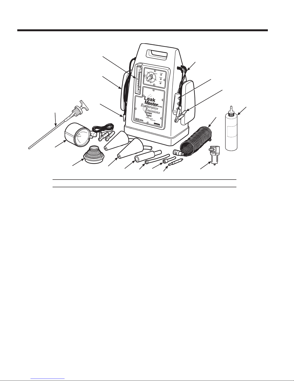
Tester Overview
Component Descriptions
1. Cap Plug Kit is used to seal the intake ducting of
the engine being tested. The plugs range in size from
1-3/4" to 4-1/2", and may be used to seal either the
inside diameter of an opening, or ip them over and
seal the opening at the outside diameter.
2. EVAP Service Port Adapter
(standard size)
connects directly to the factory service access port on
the vehicle when connecting to a vehicle’s fuel vapor
recovery system.
3. Exhaust Cones taper in size from 1" to
3-1/2" with a 5/16" opening at the small
end of the cone to which a short section
of hose is connected. The supply nozzle
is inserted into the end of the attached
hose to introduce smoke into any system
with an opening that ts these dimensions.
The exhaust cones may also be used as
exhaust plugs when testing intake vacuum
systems.
4. Flow Meter with pointer-ag establishes a quick
PASS / FAIL when determining if the vehicle being
tested has a leak.
5. EVAP Service Port Adapter (small size) connects
to the factory service access port on some vehicles.
6. “ON” Indicator Light turns ON after pressing the
remote starter button, indicating the tester is ON.
(There is a ve second self-diagnostic delay before
the light comes on.)
7. Power Indicator Light
turns ON when connecting the
power leads to a battery, indicating a good contact.
8. Remote Starter & Power Cables are used to
operate the tester. The tester stays ON for ve (5)
minutes after the remote button is pressed; press the
button again to turn the tester OFF.
9. Schrader Valve Removal / Installation Tool
is
designed to work on many different kinds of vehicles.
10. Selector Switch is used to select the functions of the
tester as explained in this manual.
11. Spotlight helps locate smoke when searching for
leaks.
12. Smoke Diffuser is designed to slow the velocity of
the smoke exiting the supply hose. The diffuser allows
the operator to lay down a thick bed of smoke along
the door, sunroof, windshield, and window seams, so
any air disturbance caused by unwanted airow may
be observed.
13. Supply Hose is used when conrming the integrity
of an EVAP system, when verifying any system for
leaks, or when introducing smoke into a system being
tested for leaks.
14. Hose (25 ft.) is used to deliver nitrogen to the EVAP
tester. Simply connect the 1/4" pipe thread to the
nitrogen regulator and the quick-disconnect tting to
the EVAP tester.
Features Included But Not Shown Here
Drain / Fill Area (located on the top-back of the tester):
Much like a motor oil dipstick, there are low and high marks
engraved on the tester’s dipstick. Remove the dipstick
to maintain the smoke solution level at the FULL mark,
and to drain and replace the smoke solution during yearly
maintenance service.
Smoke-Producing Solution: LeakMaster is shipped
with a full charge of smoke-producing solution – enough
to perform approximately 500 tests before needing a rell.
We recommend replacing the solution once a year (at the
minimum) to help keep the LeakMaster operating in a
like-new condition for many years to come.
Water Separator / Filter (on back of tester) ensures a
clean supply of nitrogen or air.
12
3
4
5
6
7
8
9
10
11
12
13
14

6
Setup
1. Connect the red power cable from the LeakMaster
to a 12V
DC power supply. If you are using a battery,
verify it is in good condition and fully charged. See
Figure 1.
2. Connect the black ground cable from the
LeakMaster to the vehicle’s chassis ground.
Connect black
battery clip to
chassis ground.
Connect red
battery clip to
positive battery
terminal.
3. Depending on the tests you are performing, connect
either a nitrogen or shop air supply line to the water
separator located on the back of the tester. See
Figure 2. Supply pressure must be between 50 psi
and 125 psi.
When testing EVAP systems: Connect the
nitrogen line to the water separator.
When testing systems other than EVAP:
Connect the air supply line to the water separator.
Remember, all tests performed with
the LeakMaster are performed with the
vehicle engine OFF.
CAUTION: To prevent
personal injury, do NOT connect
LeakMaster’s black cable to a
battery ground, because a spark
in the vicinity of the battery can
cause an explosion.
Figure 2
Water
Separator
Figure 1
7
Phase One
1. Verify the vehicle’s fuel level is below the base of
the fuel tank neck.
2. Determine if the vehicle’s EVAPsystem is governed
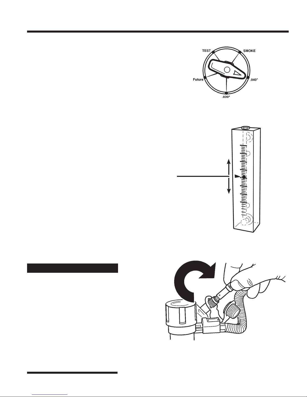
by a .040 or .020 acceptable leak standard.
3. Position the selector valve on the tester control
panel to the correct standard. See Figure 3.
The “future” setting on the control valve is
reserved for another standard, should requirements
change.
4. Turn the tester ON by pressing the remote starter
button. Observe the ow meter’s indicator ball.
Position the ow meter’s red ag so it aligns with
the ball. See Figure 4.
This measurement indicates the vehicle’s
Pass / Fail line.
5. Press the remote starter button again to turn the
tester OFF.
6. Locate the vehicle EVAP service port. Remove the
green cap and the Schrader valve that is located
inside the service port. See Figure 5.
IMPORTANT: The Schrader valve is installed
with a left-hand thread.
7. Install the EVAP service port adapter (provided
with the tester) into the EVAP service port.
Tech Tips
The EVAP service port on OBD-II vehicles
was designed with a Schrader valve before
this smoke-producing test procedure was
developed for diagnosing EVAP leaks.
Smoke, when passed through a Schrader
valve, will partially condense. It will not be
dense enough to be effective for EVAP leak
diagnosis.
For this reason, when testing with smoke,
remove the Schrader valve before
introducing smoke into the EVAP system.
Remember to turn the Schrader valve
in a clockwise rotation to remove it.
Figure 3
Figure 4
Fail
Pass
Figure 5
Turn the
Schrader valve
clockwise to
remove it.

8
Phase One
8. Insert the supply hose from the tester into the EVAP
service port adapter. See Figure 6.
9. Close the vehicle’s EVAP system vent solenoid.
10
.Set the tester’s control valve to TEST.
11.
Press the remote start button to activate the tester.
At the beginning of the test procedure, the ow
meter’s indicator-ball is toward the top of the
ow meter scale. This indicates the EVAP System
is being lled. Usually in less than 60 seconds
– depending on capacity and fuel system level –
the ball will fall within the meter’s visible scale.
Continue to ll the system until the ball stops
descending. This could take an additional two
minutes.
The timer will automatically turn OFF in five
minutes. (The tester will turn OFF if the remote
switch is pressed again before the 5 minutes has
elapsed).
12.
Once the flow meter’s ball stops descending,
observe if the ball is above or below the red ag.
See Figure 7.
• AmeasurementABOVEthe pointer-ag
indicates an unacceptable leak in the EVAP
System (FAIL). Proceed to Phase Two.
• A measurement BELOW thepointer-ag
indicates no leak (or an acceptable leak)
in the EVAP System (PASS).
Figure 7
Fail
Pass
Tech Tips
•When testing a pre-OBD vehicle, or when
testing an OBD vehicle without an EVAP
service port, access the EVAP system in one
of two ways: disconnect the EVAP vent line
leading back to the fuel tank; or go through
the fuel tank neck using a fuel neck adapter
(not supplied).
•A common leak in a vehicle’s EVAP system
is due to an unsecured or faulty fuel cap.
We recommend NOT disturbing the fuel
cap before completing Phase One.
If an unacceptable leak has been deter-
mined after completing Phase One, you can
reposition or test the fuel cap, then perform
Phase One again. You may discover the
leak was due to a fuel cap problem.
If you disturb the fuel cap before perform-
ing Phase One, and the vehicle passes the
test, you will never know for sure if the
leak was due to the fuel cap or if you are
dealing with an intermittent condition.
Service Port
Service Port
Adapter
Supply
Line
Figure 6

9
Phase Two
1. Verify the vehicle’s fuel level is below the base of
the fuel tank neck.
2. Position the selector valve on the tester to SMOKE.
See Figure 8.
3. Remove the vehicle’s fuel cap.
ThissavestimewhenllingtheEVAPsystemwith
smoke.
4. Press the remote starter button to activate the tester.
The “ON” indicator light will come ON after a
5-second self-diagnostic delay, indicating the tester
is ON and producing smoke.
5. Replace the fuel cap once smoke is seen exiting the
fuel tank’s neck.
ThetimerwillautomaticallyturnOFFinveminutes.
ToshutthetesterOFFbeforetheveminutesareup,
simply press the remote button.
6. Continue to introduce smoke into the EVAP system
for about 60 seconds, or until the ow meter’s ball
stops descending.
It is not necessary to wait until the system is full
(indicatedbythedescendingowmeterball)before
looking for leaks.
7. Use the spotlight provided to follow the EVAP
path and look for smoke exiting a leak. Continue to
introduce smoke in 30 second intervals until the leak
is found.
This ON/OFF technique allows the EVAP system to
achieve test pressure, and then allows the pressure to
be relieved. Diagnostic Smoke®vapor is even more
visible at lower test pressures.
You could also use a UV light (not provided) to search
for the UltraTraceUV ®dye that would be deposited
at the exact location of the leak(s). The longer the
EVAP system is allowed to fill with Diagnostic
Smoke®vapor,themoreuorescentmaterialwillbe
deposited.
8. Repair the leak(s), and perform the Phase One test
again to verify the repair and make certain there are
no additional leaks in the EVAP system.
9. Reinstall the vehicle’s Schrader valve using a
counterclockwise thread rotation (OBD vehicles
only). Reinstall the EVAP service port green cap.
Figure 8
Tech Tips
•For an even quicker test procedure, it is
possible to combine Phase One and Phase
Two. Theowmeteris operational in both
phases.
If you already know the EVAP system has a
leak, start with Phase Two testing. (The leak
willstillbequantied,becausetheowmeter
is active.)
Then perform Phase One to verify the repair.
•If you are testing a vehicle that has a fuel roll-
over valve in the fuel tank, you may not see
smoke exiting the fuel tank neck.
You may need to introduce smoke through the
fuel tank neck, and vent the non-smoke air out
the vehicle’s service port; or at least partially
llthesystemwithsmokebeforeclosingthe
vent solenoid. Then, once smoke is seen exiting
the vent area, close the vent solenoid.
10
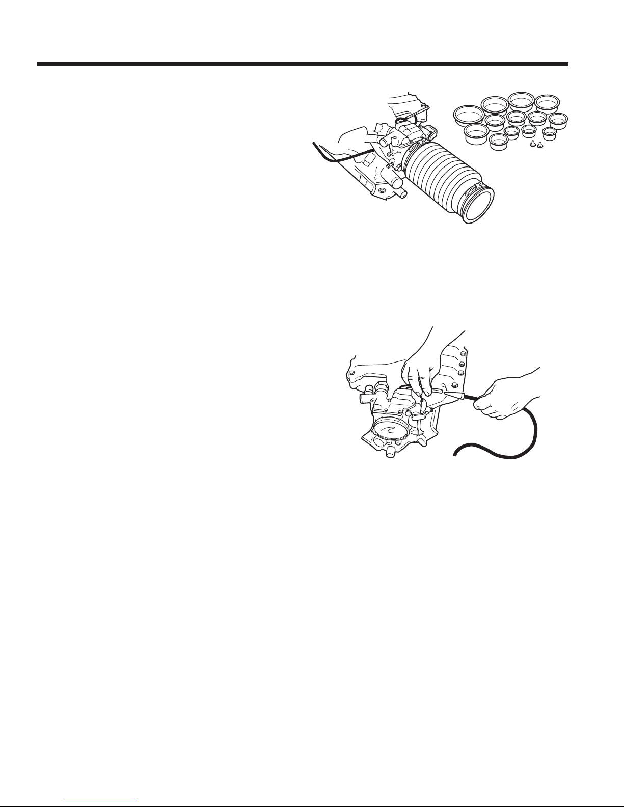
1. Seal the system to be tested by selecting the correct
size cap plug (supplied) and sealing the engine’s
air intake.
To inspect the entire system, it is best to seal the
engine’s intake as close as possible to the air inlet
origin. This is especially important on engines
equippedwith mass airow sensorsandrelated
ducting connecting it to the intake system.
2. Select a vacuum line on the engine that is easily
accessible, and insert the tester’s tapered smoke
nozzle into a section of this line that goes to the
engine.
The supply line to the brake booster is a good place
to introduce smoke into the intake manifold. Enter
this line at a point where the check valve will not
interfere(orstoptheowofsmoke).
3. With the engine shut OFF, press the remote button
once to turn the tester ON. Let the tester run until
the system is filled – usually 30 seconds to 1
minute.
4. Once smoke is observed exiting a leak, push the
remote button a second time to turn the tester
OFF.
5. Turn the tester ON and OFF in 30 second intervals
to pinpoint the source of the leak.
6. Use the spotlight to identify the origin of the
smoke, or use a UV light (not supplied) to look for
residual traces of the dye that was left behind by
the smoke.
Theexitingsmokedepositsaresidualuidthatis
either bright green or bright yellow in color when
viewed with a UV light.
Vacuum and Induction Leaks
One method to seal the system: Disconnect the rubber
hose at the air cleaner, and plug the end of the hose.
Cap Plugs
Select a vacuum line that is easily accessible, and insert
tester’s tapered smoke nozzle.

11
Vacuum and Induction Leaks
Typical Areas to Search on Fuel Injected Engines
Typical Areas to Search on Carbureted Engines
Air Cleaner
Hose
Loose
Clamps
Throttle Body
Shaft
Throttle Body Gasket
Injector O-ring
Positive Crankcase Vent Hose
(PCV)
Vacuum
Lines Air
Valves
Vacuum
Lines Throttle
Plate
Air Flow Meter
Intake Manifold
Air Cleaner Assembly
Injector
O-rings
Vacuum
Lines
Exhaust Gas
Recirculating Valve Vacuum
Hose Vacuum Switches
Vacuum Hose
Connections
Vacuum
Advance
Module
PCV Valve
& Hoses
Carburetor
Base
Gasket
Intake Manifold
Gasket
Choke Pull Off
Diaphragm

12
Vacuum and Induction Leaks
EGR Valve Leaks
The exhaust gas recirculating valve is at the heart of
the emission control system. Since the EGR valve
operates in such a hostile environment, it is always
susceptible to leakage. During a normal test for
vacuum leaks, the EGR valve will be exposed to
smoke and may show leaks at the seat, diaphragm, or
even the base gasket.
If smoke is seen exiting the EGR valve, disconnect the
vacuum supply line, and introduce smoke directly into
the valve. This will verify if the diaphragm is leaking,
or if the valve is leaking at the seat.
Smoke may also be used to check EGR ports for
restriction. Open or remove the valve, and introduce
smoke through the tail pipe to verify these ports are
open.
Idle Motors and Solenoid Leaks
A small leak in an idle motor or solenoid component
can make an engine idle rough or stall. Leaks in these
components are usually found during a normal vacuum
leak test. It is not unusual to nd base gaskets and
o-rings leaking in and around motors and solenoids.
Brake Booster Leaks
A leaking vacuum brake booster not only affects
engine performance like other types of vacuum
leaks, but more importantly, it can seriously affect the
stopping power of the vehicle.
Pressing on the brake pedal during this test
will falsify the test results.
1. Disconnect the vacuum supply line and the check
valve from the brake booster.
2. Insert the smoke supply nozzle into the brake
booster, and press the tester’s remote button once
to begin introducing smoke.
3. If the tester’s ow meter indicates ow, the brake
booster has a leak.
4. Under the hood, look for smoke exiting around the
crimped area of the booster canister. Also look for
smoke inside the vehicle under the dash.
Tech Tips
Testing the EGR Pintle Shaft – This will help
you diagnose a good or bad EGR valve and
other “metered” leaks.
1. Do not cap off any part of the engine –
leave it in a normal operating state (but
not running). Insert the LeakMaster supply
hose into a direct vacuum manifold source,
such as a brake booster hose or PCV. Press
the remote button on the LeakMaster. Watch
for smoke to escape from the EGR valve. If
you see a lot of smoke, the valve is bad; no
smoke, move on to the next step.
2. Cap off the intake using one of the cap plugs
supplied with the LeakMaster. Insert the
exhaust cone into the tailpipe. (The hose
on the exhaust cone should be plugged with
the cap plug provided.) Now that the system
is sealed, press the remote button and
watch for smoke. A small amount of smoke
indicates an acceptable EGR valve.

13
Exhaust Leaks
The exhaust cones were developed for the identi-
cation of leaks in a vehicle’s exhaust system. These
leaks can be difcult to locate, because they are often
hidden by metal shields, or become silenced as the
engine warms up.
1. Put the vehicle on a lift to expose the underside.
2. With the engine OFF, insert the exhaust adapter
cone into the tail pipe as shown.
On dual exhaust systems, install a cone in each tail
pipe.
3. Attach the tester’s SMOKE supply line to the hose
on the exhaust cone.
On dual exhaust systems, verify the other exhaust
cone is plugged with the cap plug supplied with the
cone.
4. Press the remote button once to start the ow of
smoke.
5. Using a spotlight, follow a path along the vehicle’s
exhaust system, and look for the source of the leak
(exiting smoke).
Exhaust Cones
Insert the exhaust
adapter cone into
the tail pipe.
Tech Tips
•This test is more accurate when testing a
cold exhaust system, because a very hot
catalytic converter consumes some of the
smoke. Also, many small exhaust leaks are
only visible on a cold exhaust system, due
to thermal expansion.
• Seal the vehicle’s intake system with the
cap plugs provided – this achieves correct
system pressure in the event both an intake
valve and an exhaust valve are open in the
same cylinder at the same time.

14
Miscellaneous Leaks
Oil Seals and Gasket Leaks
Many oil leaks can be located with the LeakMaster;
however, it is important to understand that the
LeakMaster will only nd leaks that allow air to ow
through them, causing the oil to bubble.
To nd oil leaks, it is necessary to pressurize the
crankcase with smoke:
1. Remove the vehicle’s oil dipstick, slip a hose over
the dipstick tube, and insert the smoke nozzle into
the hose.
2. Block or plug the PCV, air breather, and intake.
Remove the oil ller cap.
3. Introduce smoke into the crankcase until smoke is
seen exiting the oil ller port.
4. Install the oil ller cap, and continue lling the
system.
5. Use the spotlight to check for leaks, which could
appear as seeping smoke, bubbling oil with little
or no smoke, or dripping oil with no smoke at all.
Intercooler and
Turbocharger Leaks
Engine compartments with turbochargers tend to
run hotter than normally aspirated engines, causing
hoses and seals to dry out and leak. For turbocharged
systems to operate efciently, there can be no leaks in
the intercooler, ducting, exhaust, or the turbo itself.
1. Connect the smoke nozzle to the intake system.
2. Introduce smoke into this “cold” side of the
turbocharger.
3. While the intake is under smoke pressure, inspect
the intercooler, ducting, waste gate, and the cold
side of the turbo for leaks.
4. To inspect the “hot” or exhaust side of the turbo
for leaks, install the exhaust cone into the exhaust
pipe. Introduce smoke and inspect the exhaust,
the exhaust manifold, and the “hot” side of the
turbocharger.
To inspect the “hot” or exhaust side
of the turbo, install the exhaust cone
into the exhaust pipe.

15
Miscellaneous Leaks
Component Testing
(radiators, water pumps, valves, etc.)
When installing new or rebuilt parts, nothing is more
frustrating than to discover, on completion of the job,
that the component is faulty or has a leak. It is far easier
to inspect a radiator or water pump before it is installed
than to nd out later, after the antifreeze is added, that
there is a leak.
Component testing has endless possibilities; anything
from hoses to diaphragms can be tested. Supplied with
every LeakMaster are two exhaust cone adapters that
can be used to access any opening from 1" to 3-1/2".
Simply introduce smoke into the system being tested,
seal any interconnecting ports or passages, and look for
smoke to exit a leak.
Under-Dash Leaks
Under-dashboard leaks can be difcult to locate. The
LeakMaster can conrm or eliminate the possibility of
an under-dash leak in just minutes.
Most vehicles have a common vacuum supply line that
originates at the engine intake. This vacuum source
comes through the rewall to supply the climate control
functions, as well as other systems in the vehicle.
Vacuum systems under the dashboard are intended to be
closed systems; any ow through these systems would
indicate there is a leak present.
1. Set the control valve on the tester to TEST.
2.
Install the supply nozzle into the main vacuum line
(beyond the check valve) leading to the dashboard.
3. Introduce air into the system, and watch the ow
meter indicator ball. If the ball drops to zero, the
system is leak free.
4. Continue to introduce air into the system while testing
each setting on the climate control. Watch the ow
meter for any change of ow.
If the ow meter indicates ow in any of the positions
on the climate control, you will know what portion
of the system has a leak.
5. Set the control valve on the tester to SMOKE.
6. Introduce smoke into the system where a leak has
been determined. Shine the spotlight under the
dashboard, and look for smoke to pinpoint the leak.
Exhaust Cones
Tech Tips
Don’t forget that you may also identify leaks
by using an ultraviolet light (not supplied) to
look for traces of dye left behind by the smoke.
Theexitingsmokedepositsaresidualuidthat
is either bright green or bright yellow in color,
when viewed with a UV light.

16
Miscellaneous Leaks
Wind and Water Leaks
(sunroofs, windows, etc.)
The smoke diffuser was developed for quick
identication of air and water leaks in a vehicle’s
passenger compartment. These leaks can be caused
by faulty door and glass seals, windshield or sliding
roof seals, or by misalignment of any of these
components.
1. Park the vehicle to be tested indoors; avoid parking
in a windy environment.
2. Turn the ignition to the ACCESSORIES position.
3. Turn the heater/AC blower to FRESH AIR and
HIGH. (Verify the blower is NOT set to the
recirculation mode.)
4. Close the vehicle’s doors and windows. The
cabin of the vehicle is now under a slight positive
pressure.
5. Attach the smoke diffuser to the end of the tester’s
smoke nozzle.
6. Press the remote button.
7. From outside of the vehicle, position the tip of the
diffuser about 2 to 3 inches away from the vehicle,
and follow a path along the area you wish to test.
The smoke will linger on the path you are following
until a leak is present. The air exiting the vehicle
will cause the smoke to be disrupted, identifying
the source of the leak.
8. Once you nd a leak, mark its location with a wax
pencil or removable marker. Look for the cause of
the leak.
9. Turn the vehicle ignition OFF, and repair the
leak.
Diffuser
Attach the smoke diffuser to the
end of the tester’s smoke nozzle.

17
Maintenance
Dipstick
LOW
FULL
CAUTION: Use only the No. P-0716-UV
smoke-producing solution (obtained
from the manufacturer) in the LeakMaster.
Using solutions not recommended by the
manufacturer can damage the unit and cause
injury to the operator.
Checking the Smoke Solution Level
Check the smoke-producing solution in the tester
regularly, and top off the solution to the FULL mark.
(Order No. P-0716-UV.)
1. Remove the dipstick located on the back of the
tester and verify the solution level. Add solution,
if needed.
2. Install the dipstick, and then remove it again to
verify the solution level reads at the FULL mark
on the dipstick. Install the dipstick.
Replacing the Smoke Solution
We recommend changing the smoke-producing
solution in the tester at least once a year, regardless
of how often the tester has been used.
1. Remove the dipstick located on the back of the
tester.
2. Insert a suction tool into the dipstick tube,
and suction all the solution out of the smoke
chamber.
IMPORTANT: Do not damage the water
separator on the back of the tester.
3. Refull the smoke chamber by emptying 16 ozs. of
UltraTraceUV® smoke-producing solution (No.
P-0716-UV) into the smoke chamber through the
dipstick tube.
4. Install the dipstick, and then remove it again to
verify the solution level, which should read at the
FULL mark on the dipstick. Note:Donotoverll.
Install the dipstick.
5. Record your name and the date in the Fluid Change
Record in this manual.
6. Dispose of the waste smoke solution according to
local, state, and federal (OSHA) regulations.
18
Parts List
2
3
1
4
5
6
7
8
9
10
11
12
13
14
15
16
17
Item No. Part No. Qty. Description
1 6525-7 1 Remote Cable Assembly (includes switch)
2 6525-6 1 Remote ON/OFF (switch only)
3 6525-5 1 Battery Power Cable Assembly
4 CEA-041 1 Nitrogen Coiled Hose (25 ft.)
5 P-0716-UV 1 Smoke Producing Solution
6 6525-4 1 Water Trap w/ lter
7 CEA-049 1 Schrader Removal Tool
8 CEA-04 1 Standard Service Port Adapter
9 CEA-042 1 Small Service Port Adapter
10 CEA-03 1 Smoke Diffuser Adapter
11 CEA-01 1 Exhaust Cone (2 ea.)
12 CEA-02 1 Cap Plug Kit
13 HS-400AC 1 Halogen Spotlight
14 6525-2 1 Dipstick
15 6525-8 1 Brass Nozzle
16 6525-9 1 Brass Nozzle and Hose Assembly
17 6525-3 1 Pointer Flag (forowmeter)
Parts Included but Not Shown
6525-10 1 Rubber Feet (4 reqd.)
6525-11 1 Accessory Storage Bag
6525-12 1 Tech Tips Manual
107360 1 Operator’s Manual
Optional Parts Not Included
6625 1 EVAP Cart
6525-1 1 Pressure Regulator

19
Troubleshooting
Diagnostic Lights
The LeakMaster has three diagnostic lights on the control panel that indicate if the tester is working correctly.
The following table describes the tester’s trouble codes.
Interval Probable Cause
√ Constant ON (switch in SMOKE position; smoke venting into atmosphere; Low oil
ow meter ball indicates ow)
√ Constant ON (switch in SMOKE position; system being tested; ow meter Normal temp. control function
ball near zero)
√ Occasionally blinks Normal temp. control function
√ ConstantON Sufcientpower
√ Blinkseveryone(1)second Insufcientpower
√ √ Blink simultaneously every one (1) second Power connection at battery is
loose or short in heating circuit
√ √ Blink simultaneously @ four (4) blinks per second Open heating circuit
√ √ Blink alternately @ one (1) blink per second Circuit board failure
j
j
Ifacircuitboardfailureoccurs,rsttrydisconnectingpowertotheunitfor10seconds;thenreconnectpower.Ifthisfailure
code occurs a second time during operation, disconnect the tester and contact the manufacturer.
Diagnostic Lights
Green
Red
Yellow
Troubleshooting Guide
Problem Cause Solution
Green power indicator lamp on
the tester does not come ON.
1. Power cables are reversed.
2. Poor power supply cable
connection.
3. Battery providing power is too
weak.
1. Correctly position the power cables.
2. Secure the connection at positive
terminal and chassis ground.
3. Verify battery is in good condition
and fully charged.
Smoke does NOT come out of
the fuel neck area when lling
the system with smoke during
Phase Two.
1. Fuel tank level is too high and is
blocking the fuel neck passage.
2. Vehicle has a roll-over valve
preventing pressure relief through
the tank neck.
1. Reduce the fuel level in the tank so it
is below the base of the fuel tank neck.
2. Introduce smoke from the fuel tank;
or if possible, disable the roll-over
valve;orpartiallyllthesystemwith
smoke before closing the vent solenoid.
Tester is ON, but NO smoke or
air coming out of hoses.
1. Poor power supply cable
connection.
2. Battery providing power is too
weak.
3. Tester’s internal solenoid is
stuck closed.
1. Secure the connection at positive
terminal and chassis ground.
2. Verify battery is in good condition
and fully charged.
3. Disconnect the air or nitrogen quick-
release at the tester’s water separator,
and then reconnect it.
Table of contents
Other SPX Measuring Instrument manuals


Popular Measuring Instrument manuals by other brands


Bosch
Bosch Professional GLM 50-22 Original instructions

POSITAL
POSITAL ACS-080 manual

Svantek
Svantek SV105 instruction manual

Desco
Desco Statguard Flooring D19290 Installation, operation and maintenance

Incra
Incra V27 instructions

VERIS INDUSTRIES, INC.
VERIS INDUSTRIES, INC. E31E Series installation guide