Control. Monitor. Protect
»Control. Monitor. Protect
»
Electronic Potentiometer Function
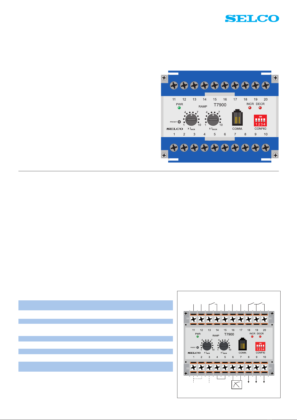
When the CONFIG dipswitch no. 1 on the
front is OFF, the T7900 will act as an
electronic potentiometer. The output is a
variable voltage, current or pulse width
modulated signal (PWM).
The type and range of output can be
selected via dipswitches on the back of
the unit. This selection should be made in
order to match the input type and range
of the unit to control e.g. an electronic
speed controller. The following can be
selected on the dipswitches:
Setting all dipswitches to ON will put
the unit in programming mode. In
programming mode the unit can be
congured from a PC using a standard
ANSI terminal such as the Windows Hy-
perTerminal. In this case additional out-
put ranges, reference levels and
other parameters can be specied from
the PC. An optional programming kit
G0100 is available for this purpose.
The control inputs are the increase / de-
crease contact inputs on terminals 18
and
20. As long as no increase / decrease
in-
puts have been received, the output sig-
nal will stay at the reference level.
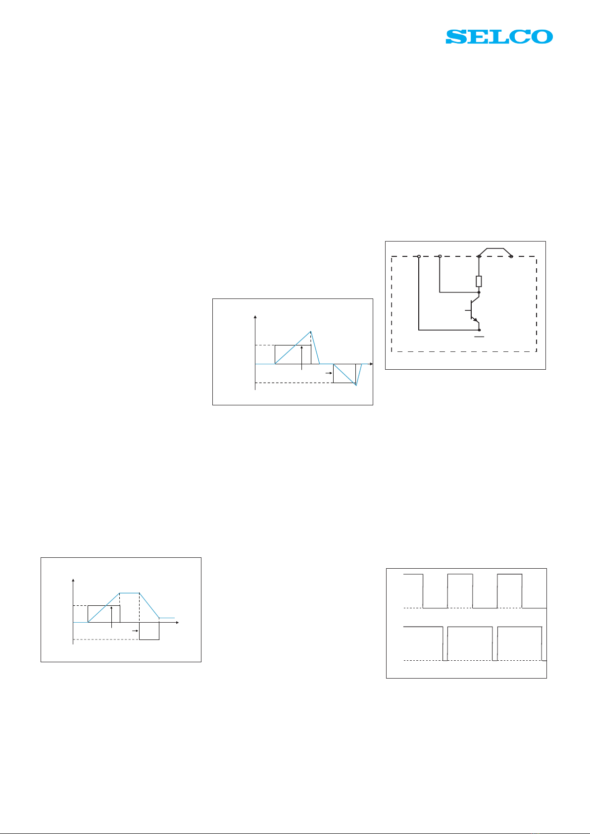
Fig. 2 illustrates the normal output
characteristic. When an increase signal is
applied to the T7900, the output signal
will increase until the increase signal is
interrupted. The ramping of the increase
is determined by the setting of tINCR in
such a way that lower settings will cause
faster ramps.
When a decrease signal is applied to the
T7900, the output signal will decrease
until the decrease signal is interrupted.
The ramping of the decrease is
determined by the setting of tDECR.
When using a PC for conguration, it is
also possible to select a different type of
output characteristic, a so called “rubber
band” output characteristic where the
output automatically goes back to the
reference level when the increase or
decrease signal is interrupted.
In this case, the ramping of the increase
and decrease is a little different. They are
both the same, determined by the setting
of tINCR, whe reas the ramping of going
back to the reference level is now
determined by the setting of tDECR. This
is illustrated in gure 3.
The ramping times tINCR and tDECR can be
set on the two dials on the front panel.
The ramping times have the following
ranges:
0.25 s / V – 2.5 s / V
0.25 s / mA – 2.5 s / mA
0.04 s / % – 0.4s / %
The ramping time tINCR can be multiplied
by 10 by setting the CONFIG dipswitch
3 to on and the ramping time tDECR can be
multiplied by 10 by setting the CONFIG
dipswitch 4 to ON.
2.5 s / V – 25 s / V
2.5 s / mA – 25 s / mA
0.4 s / % – 4s / %
The function of the CONFIG dipswitches
on the front is as follows:
SW1 ON: POWER REF
SW2 ON: INVERT
SW3 ON: INCR ramp*10
SW4 ON DECR ramp*10
Dipswitch no. 1 should be OFF when
T7900 is used as an electronic
potentiometer, and on when T7900 is
used as a power reference unit.
Dipswitch no. 2 can be used for inverting
the output, e. g. going from 10V to 0V
rather than from 0V to 10V. Dipswitches
nos. 3 and 4 are the dipswitches mentio-
ned previously for multiplying the ramp
times by 10.
The output reference level can be set or
changed by adjusting the output signal to
the desired level and then briey activate
the PRESET push button on the front of
the unit.
PWM Output (terminals 10 and REF)
This type of signal is used as input in
some speed controllers (e.g. Woodward
& Caterpillar) because the signal is found
Output signal
(e.g.voltage)
t
INCR
t
DECR
Input pulse signals
INCR
REF
DECR
SW1 SW2 SW3 SW4 Output Ref.
1 2 4 8
OFF OFF OFF OFF -10V – +10V 0V
OFF OFF OFF ON 0V – +10V +5V
OFF OFF ON OFF -5V – +5V 0V
OFF OFF ON ON -10V – 0V -5V
OFF ON OFF OFF -1V – 0V 0V
OFF ON OFF ON 0V – +1V 0V
OFF ON ON OFF 0V – +3V 0V
OFF ON ON ON 0V – +5V 0V
ON OFF OFF OFF 0V – +6V 0V
ON OFF OFF ON -1V – +1V 0V
ON OFF ON OFF -3V -- +3V 0V
ON OFF ON ON
ON ON OFF OFF 10-90% 2.94KHz 50%
ON ON OFF ON 4mA – 20mA 12mA
ON ON ON OFF 10-90% 500Hz 50%PWM
ON ON ON ON PRG. MODE
Fig. 2. Normal output characteristic.
Output signal
(e.g. voltage)
t
DECR
t
INCR
t
DECR
Input pulse signals
t
INCR
INCR
REF
DECR
Fig. 3. “Rubber band” output characteristic.
Fig. 5. Pulse width modulated signal (PWM).
The range of the pulse width is 10% - 90%
in default conguration. The reference
point is 50%. Voltage, pulse and REF can
be altered via PC conguration.
Figure 5 illustrates a PWM signal of 50%
and 90%. The default reference is 50%.
However, this can be changed using PC
conguration or by using the PRESET
push button.
Fig. 4. T7900 PWM Output
less sensitive to noise rather than a volta-
ge or current input.
The PWM output of T7900 is an open col-
lector output with a 1kΩ pull up resistor
as shown in gure 4. In factory default
this output gives +10V when the transis-
tor is closed and 0V (REF) when open. Ex-
ternal voltages can be used by removing
the bridge between terminals 4 and 5 and
connecting and external voltage (max. 24
V DC) between terminals 5 and REF.
The frequency of the PWM signal is
500HZ or 2,94 KHz dependending on the
dip switch settings.