Sel SEL-9192 User manual

Schweitzer Engineering Laboratories, Inc. SEL-9192 Data Sheet
Utility Grade Dial-Up Access
Major Features and Benefits
The SEL-9192 Utility Grade USB Modem provides traditional dial-up access to remote locations where harsh
utility grade environmental specifications are required.
➤Wide Temperature Range. Operation temperature from –40° to +85°C (–40° to +185°F).
➤Standard Input Voltage. Input voltage 5–30 Vdc. Power from an external source, through the USB-B
connector, or through the DB-9 connector.
➤Easy Configuration. Uses standard and extended AT command set.
➤Compression and Speed. Allows data speeds from 300 bps to 56 kbps. Supports V.44 and V.42bis
data compression.
➤Durable and Reliable. Includes Telco line surge protection, a rugged case, and SEL’s 10-year warranty.
Functional Overview
The SEL-9192 is a 56 kbps dial-up modem built to withstand the extremely harsh conditions in a utility envi-
ronment. Connect RTUs, communications processors, and other equipment for dial-up or dial-out engineer-
ing access or data acquisition through the DB-9 serial or USB-B connectors. Power the SEL-9192 with the
optional power supply, or internally through connected USB-B or DB-9 serial ports. Configuration is simple
with the extended AT command set (listed in Table 1).
SEL-9192 Utility Grade
USB Modem

SEL-9192 Data Sheet Schweitzer Engineering Laboratories, Inc.
2
Applications
The SEL-9192 is ideally suited for point-to-point and point-to-multipoint dial-up access applications in harsh
environments and extreme temperatures. Use the SEL-3025 Serial Shield®in conjunction with the SEL-9192 to encrypt
all serial traffic across the dial-up link.
Dial-Up or Dial-Out
Figure 1 shows typical point-to-point dial-up access for data acquisition of a device. Connect the SEL-9192 to individual
IEDs or connect to a communications processor to retrieve data for several IEDs in a given location. Devices that support
dial-out communication can send events or other information to the host computer.
Figure 1 Dial-Up or Dial-Out Point-to-Point SCADA Communication
Figure 2 illustrates use of the SEL-9192 in a point-to-multipoint SCADA communications scheme. The host computer
can access any number of dial-up devices by serially dialing each SEL-9192 connected to those end devices.
Figure 2 Dial-Up Point-to-Multipoint SCADA Communication
Add an SEL-3025 to your dial-up network to create a secure dial-up environment, as shown in Figure 3.
Figure 3 Secure Dial-up Engineering Access Channel
Manage IED engineering access through a communications processor such as the SEL-2032, SEL-3530 RTAC, or the
SEL-3354 Embedded Automation Computing Platform, as shown in Figure 4. Connect the modem via USB-B or the
SEL-C431 cable to the communications processor.
SEL-9192 SEL-9192
SEL-351
51
SEL-9192
SEL-351
51
SEL-9192
SEL-351
5
1
SEL-9192
SEL-351
51
SEL-9192
SEL-9192
SEL-351
3
5
1
SEL-9192
SEL-3025 SEL-3025

Schweitzer Engineering Laboratories, Inc. SEL-9192 Data Sheet
3
Figure 4 Engineering Access Through a Communications Processor
Use an SEL-3610 Port Server to create a modem pool with as many as eight port-powered SEL-9192 modems and as
many as nine additional externally-powered SEL modems, as shown in Figure 5.
Figure 5 Modem Pool Application
Configuring
To configure the SEL-9192, install the SEL USB-to-
UART driver (contained on the CD and also available on
the SEL website), then connect a USB-B cable into the
USB port of the modem and into a USB-A port of your
PC.
Apply power to the modem in one of the following ways:
➤Connect a USB-B cable to the modem and to the
USB-A connector on your PC. The modem is auto-
matically powered through USB. Note that if your
PC runs on Windows®, you must first install the
SEL USB-to-UART driver.
➤Connect an external +5 Vdc power supply (SEL
part number 230-0600) by inserting the 2.5 mm
barrel connector of the supply into the mating jack
on the modem.
➤If the DTE device supports +5 Vdc power output
on serial Pin 1, connect an SEL-C431 cable to the
modem and DTE device. Locate the 5 V Pin 8
switch positioned between the Telco and DB-9
connectors. Slide the switch to the ON position to
use port power on Pin 8 or slide the switch to the
OFF position to use a straight-through serial cable
with no power on Pin 8.
Use the SEL-C431 cable to connect to an SEL DTE
device in a DNP dial-out scenario. The SEL-C431 cable
can be no more than three meters (10 ft) in length.
Figure 6 SEL-C431 Cable
SEL-9192
SEL-351
51
SEL-9192
SEL-351
5
1
SEL-9192
SEL-3354
SEL-3530 RTAC
SEL-3610
TEAM Sever
Ethernet
SEL-9192
SEL-9192
SEL-9192
SEL-9192
SEL-9192
SEL-9192
SEL-9192
SEL-9192
9-Pin Male
D-Sub Connector
DB-9-P
81
2
3
2
3
5
CTS DCD
RXD RXD (OUT)
TXD TXD (IN)
GND
Pin
Func.
GND 5
77RTS RTS
18+5 Vdc +5 Vdc* (CTS)
SHELL No Connection
SEL-C431 Cable
SEL (DTE) SEL-9192
Modem (DCE)
1–10 Feet
9-Pin Male
D-Sub Connector
DB-9-P
9 Conductor 22 AWG 7/30 Tinned Copper with PVC Jacket
(Shielded: Alpha 1298C or equal; Unshielded: Alpha 1179 or equal)
BROWN
ORANGE
RED
GREEN
BLACK
YELLOW
SHIELD
Pin
Func.
Pin
#
Pin
#
Comments: Use part # 144-1000 to connect the shield to the shell.
*Enable +5 Vdc switch on the SEL-9192 Modem

SEL-9192 Data Sheet Schweitzer Engineering Laboratories, Inc.
4
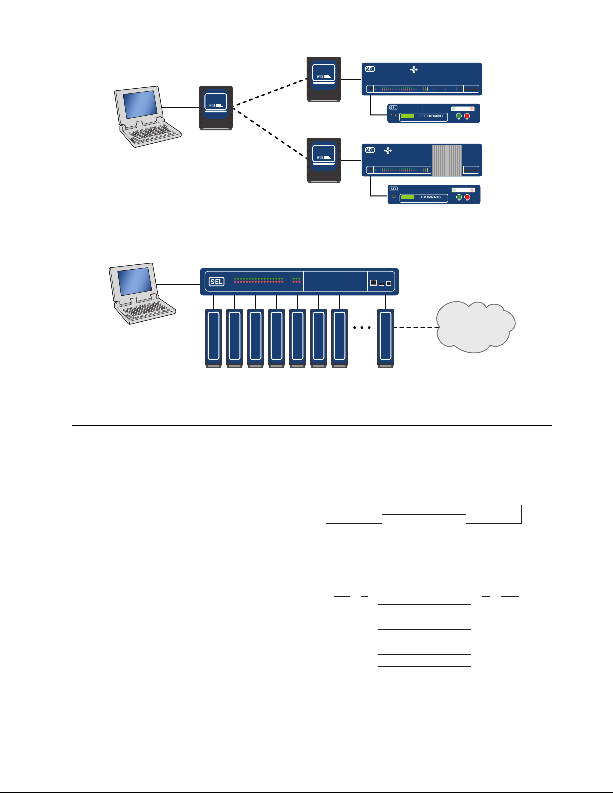
If you are using a Windows operating system on a PC to
communicate with dial-up devices through the modem,
you will need to install the Windows modem driver
contained on the SEL-9192 Modem Drivers CD or on the
SEL website. Install the driver before attempting to
configure any communications connections to the
modem.
The modem driver allows PC software, including
terminal emulation programs, to communicate with the
modem via USB or serial communications. Install the
modem driver by following the directions for your
version of Windows.
For Windows XP perform the following steps:
Step 1. Ensure that you have installed the SEL
USB-to-UART driver and downloaded the
Windows XP modem driver from the
SEL-9192 modem webpage on the SEL
website.
Step 2. Connect the SEL-9192 modem to the PC
using a USB-B cable. Wait until the
modem power LED is illuminated.
Step 3. If Windows presents a Welcome to the
Hardware Update Wizard dialogue, click
Cancel.
Step 4. From the Start menu, open the Control
Panel and double-click System.
Step 5. On the Hardware tab, click Device
Manager.
Step 6. Under Other devices, right-click Analog
Modem and select Update driver.
Step 7. On the window that follows, select No,
not at this time and click Next.
Step 8. Choose Install from a list or specific
location (Advanced).
Step 9. Click Browse and navigate to the
SEL-9192 Modem CD or the location
where you downloaded the Windows XP
modem driver from the SEL website, then
press Next.
Step 10. Wait for the driver installation to finish,
then click Finish.
For Windows 7, 64 bit perform the following steps:
Step 1. Ensure that you have installed the SEL
USB-to-UART and downloaded the
Windows 7 modem driver from the
SEL-9192 modem webpage on the SEL
website.
Step 2. Connect the SEL-9192 modem to the PC
using a USB-B cable. Wait until the
modem power LED is illuminated.
Step 3. From the Start menu, open Control
Panel > System > Device Manager.
Step 4. Under Other devices, right-click Analog
Modem and select Update driver.
Step 5. Select Browse my computer for driver
software.
Step 6. Select Let me pick from a list of device
drivers on my computer.
Step 7. Double-click Modems from the list. Your
PC will give a list of available standard
modem drivers.
Step 8. Scroll down the Manufacturer list to
Conexant. Under Models, select
Conexant Compatible Internal
V90,K56Flex,Voice,Speakerphone, then
click Next.
Step 9. Click Ye s on the warning about updating
drivers.
Step 10. Click Close to finish the installation.
Configure the modem using a terminal emulation
program or ACSELERATOR QuickSet®SEL-5030
Software’s terminal screen with AT commands. Enter
AT (ATtention) followed by the command, parameters, if
any, and a carriage return. The modem will reply with OK.
AT Command Example
This example uses the SO command to instruct the
modem to automatically answer after it detects two
consecutive rings.
ATSO=2 <Enter>
OK
Table 1 contains basic AT commands. Table 2 through
Table 6 contain extended AT commands. The general
format is ATXn, where Xis the command given in the table
and nis a parameter required for some of the commands.
Ensure that you save the settings into NVRAM when you
are finished with the AT&W0 command so that the
settings will remain through power outages.

Schweitzer Engineering Laboratories, Inc. SEL-9192 Data Sheet
5
Table 1 AT Commands (Sheet 1 of 2)
Command Description
A/ Repeat the previous AT command
AAnswer
BnSelect CCITT or Bell standard
B0 CCITT operation at 300 or 1200 bps
B1 Bell operation at 300 or 1200 bps (default)
DDial
0–9 Dial DTMF digits 0 to 9.
A–D Dial DTMF digits A, B, C, and D.
P Select pulse dialing; affects current and subsequent dialing.
T Select tone dialing; affects current and subsequent dialing.
! Flash—go on-hook for a time defined by S29.
S=rDial stored number r(see &Z for storing numbers).
W Wait for dial tone detection before dialing the next digit. If no dial tone is detected within the time specified by S7, the
modem aborts the rest of the sequence, goes on-hook, and generates an error message.
@ Wait for 5 seconds of silence before proceeding with next dialing string and then complete handshake sequence.
, Pause—the modem pauses for a time specified by S8 before dialing the following digits. Most often used when dialing an
outside line through a PBX.
; Return to command mode after processing command.
^ Disable calling tone transmission; applicable to current dial attempt only.
Example of the Dial command: ATDT767-8900 Meaning “ATtention Dial using Touch-tone the numbers 767–8900”
EnCommand echo
E0 Disables command echo.
E1 Enables command echo (default).
HnDisconnect (hang up)
H0 Hang up (default)
H1 Go off-hook
InModem identification
I0 Reports product code (either 33600 or 56000).
I1 Reports 255 if the prestored checksum value is FFh.
I2 Reports OK (for software compatibility).
I3 Reports the firmware version of the modem—Example: 3.xxx-V90_2M_DLS.
LnSpeaker volume
L0 Off or low volume
L1 Low volume (default)
L2 Medium volume
L3 High volume
MnSpeaker control
M0 Speaker is always off.
M1 Speaker is on during call establishment, but goes off when carrier is detected (default).
M2 Speaker is always on.
M3 Speaker is off during dialing and when receiving carrier, but on during answering.

SEL-9192 Data Sheet Schweitzer Engineering Laboratories, Inc.
6
QnQuiet results codes control
Q0 Enables result codes to the DTE (default).
Q1 Disables result codes to the DTE.
SrRead or write to S-register r
rEstablishes S-register ras the default register.
r= nSets S-register rto the value n.
r? Reports the value of S-register r.
VnResult code form
V0 Enables short-form (terse) result codes.
V1 Enables long-form (verbose) result codes (default).
WnError correction message control
W0 Upon connection, the modem reports only the DTE speed (e.g., CONNECT 9600). Subsequent responses are disabled
(default).
W1 Upon connection, the modem reports the line speed, the error correction protocol, and the DTE speed. Subsequent responses
are disabled.
W2 Upon connection, the modem reports DCE speed (e.g., CONNECT 2400). Subsequent responses are disabled.
XnExtended result codes
X0 Ignores dial and busy tone. Sends CONNECT message when a connection is established by blind dialing.
X1 Disables monitoring of busy tones; sends only OK, CONNECT, RING, NO CARRIER, and ERROR. If busy tone detection
is enforced and busy tone is detected, NO CARRIER will be reported instead of BUSY. If dial tone detection is enforced or
selected and dial tone is not detected, NO CARRIER will be reported instead of NO DIALTONE.
X2 Disables monitoring of busy tones. Sends only OK, CONNECT, RING, NO CARRIER, ERROR, NO DIALTONE, and
CONNECT XXXX. If busy tone detection is enforced and busy tone is detected, NO CARRIER will be reported instead of
BUSY. If dial tone detection is enforced or selected and dial tone is not detected, NO CARRIER will be reported instead of
NO DIALTONE.
X3 Enables monitoring of busy tones; sends only OK, CONNECT, RING, NO CARRIER, ERROR, NO DIALTONE, and
CONNECT or CARRIER XXXX. If dial tone detection is enforced and dial tone is not detected, NO CARRIER will be reported.
X4 Enables monitoring of busy tones; sends all messages (default).
Z0 Soft reset
Table 1 AT Commands (Sheet 2 of 2)
Command Description
Table 2 AT& Commands (Sheet 1 of 2)
Command Description
&CnData carrier detect (DCD) option
&C0 DCD remains ON at all times.
&C1 DCD follows the state of the carrier (default).
&DnData terminal ready (DTR) option
&D0 Ignores DTR.
&D1 Enter the escape mode when ON-to-OFF transition is detected on DTR.
&D2 Hangs up, assumes command state and disable auto-answer upon detecting ON-to-OFF transition of DTR (default).
&D3 ON-to-OFF transition causes the modem to perform a soft reset. It is the same as if an AT Z command is issued.
&FnRestore factory configuration (profile)
&GnSelect guard tone.
&G0 Disables guard tone (default).
&G1 Enables 550 Hz guard tone.
&G2 Enables 1800 Hz guard tone.

Schweitzer Engineering Laboratories, Inc. SEL-9192 Data Sheet
7
&KnFlow control
&K0 Disables flow control.
&K3 Enables RTS/CTS flow control (default for data modes).
&K4 Enables XON/XOFF flow control.
&K5 Supports transparent XON/XOFF flow control.
&PnSelect pulse dial make/break ratio
&P0 39/61 make/break ratio at 10 pulses per second (default)
&P1 33/67 make/break ratio at 10 pulses per second
&P2 39/61 make/break ratio at 20 pulses per second
&P3 33/67 make/break ratio at 20 pulses per second
&QnSelect operation mode
&Q0 Selects direct asynchronous operation.
&Q5 The modem will try an error-corrected link (default).
&Q6 Selects asynchronous operation in normal mode (allows speed buffering and flow control but no error correction).
&SnDSR override
&S0 DSR remains ON at all times (default).
&S1 DSR becomes active after answer tone has been detected and inactive after carrier has been lost.
&WnSaves the current configuration—will save DTE speed, parity settings, AT commands, and S-registers. Modem will
default to the saved settings upon power-up or reset.
&W0 Saves the current configuration to stored profile 0.
&W1 Saves the current configuration to stored profile 1.
&V Displays current configuration.
&Zn=xStore telephone number to location n
n= 0–3 Enter store number location
x= Dial String Enter telephone number to store
Entering AT&Z2=7678900 would store telephone number 7678900 to stored number location 2. To dial this number
enter AT D S=2.
Table 2 AT& Commands (Sheet 2 of 2)
Command Description
Table 3 AT% Commands (Sheet 1 of 2)
Command Description
%CnEnables or disables data compression.
%C0 Disables data compression.
%C1 Enables MNP 5 data compression negotiation.
%C2 Enables V.42bis data compression (sets S46 bit 1).
%C3 Enables V.42bis and MNP 5 data compression (default).
%EnLine quality monitor
%E0 Disables line quality monitor and autoretrain.
%E1 Enables line quality monitor and autoretrain.
%E2 Enables line quality monitor and fall-back/fall-forward (default).
%L Line signal level
Returns a value that indicates the received signal level. For example, 009 = –9 dBm, 043 = –43 dBm.

SEL-9192 Data Sheet Schweitzer Engineering Laboratories, Inc.
8
STE Command
Use the -STE=ncommand to enable/disable Line-In-Use
and Extension Pickup options. Use Table 4 to determine the
value of nfor this command in your installation scenario.
If the line is in use and the modem issues an ATDT
command to dial out, the modem will not go off hook
and will display a LINE-IN-USE result code. If the
modem is off hook and the extension is picked up, the
modem will drop the connection.
AT+MS Select/Force Modulation
Command
This command is useful if you need to force the modem
to specific modulations or line speeds.
+MS Modulation Selection
This extended format compound parameter controls the
manner of operation of modulation capabilities in the
modem in one command. See Table 5 for valid entries.
Below is an example of how to read the current settings
using the AT +M S ? command.
=>AT+MS? <Enter>
+MS: V90,1,300,33600,300,5600
%Q Line signal quality
Reports line signal quality (DAA-dependent). Returns higher order byte of the EQM value. Based on EQM value,
retrain or fallback/fall forward may be initiated if enabled by %E1 or %E2.
Table 3 AT% Commands (Sheet 2 of 2)
Command Description
Table 4 –STE Command Options
-STE=n Value Extension Pickup Line-In-Use
0 (default) Disabled Disabled
1 Disabled Enabled
2 Enabled Disabled
3 Enabled Enabled
Where:
V90 = V.90
1 = Automode enabled
300 = min_tx_rate
33600 = max_tx_rate
300 = min_rx_rate
56000 = max_rx_rate
Table 5 +MS Command Supported Ratesa(Sheet 1 of 2)
Modulation Carrier Possible Minimum, Maximum, Receive, and Transmit Rates
Bell 103 B103 300
Bell 212 B212 1200
V. 2 1 V 2 1 3 0 0
V.22 V22 1200
V.22bis V22B 2400 or 1200
V.23 V23C 1200rx/75tx or 75rx/1200tx
V.32 V32 9600 or 4800
V.32bis V32B 14400, 12000, 9600, 7200, or 4800
V.34 V34 33600, 31200, 28800, 26400, 19200, 16800, 14400, 12000, 9600, 7200, 4800, or 2400
V.90 V90 56000, 54667, 53333, 52000, 50667, 49333, 48000, 46667, 45333, 42667, 41333, 40000, 38667,
37333, 36000, 34667, 33333, 32000, 30667, 29333, or 28000
K56flex K56 56000, 54000, 52000, 50000, 48000,46000, 44000,42000,40000, 38000, 36000, 34000, or 32000

Schweitzer Engineering Laboratories, Inc. SEL-9192 Data Sheet
9
AT S Registers
Use the AT commands to set S or settings registers in the
modem. To set an S register, type ATSr=nwhere ris the
S register number and nis the parameter value.
You can read the S register value by typing ATSr?,
where ris the register number. See Table 6 for a list of
supported S registers.
V.92 downstream V92 56000, 54667, 53333, 52000, 50667, 49333, 48000, 46667, 45333, 42667, 41333, 40000, 38667,
37333, 36000, 34667, 33333, 32000, 30667, 29333, or 28000
V.92 upstream V92 480000, 46667, 45333, 44000, 42667, 41333, 40000, 38667, 37333, 36000, 34667, 33333, 32000,
30667, 29333, 28000, 26667, 25333, or 24000
a<Automode> option parameters:
0 = Automode disabled–Fixed Modulation.
1 = Automode enabled–Automatically selected speed and modulation (default).
Table 5 +MS Command Supported Ratesa(Sheet 2 of 2)
Modulation Carrier Possible Minimum, Maximum, Receive, and Transmit Rates
Table 6 AT S Registers
Register Range Units Default Description
S0 0–255 Rings 0 Ring to answer on: ATS0=1 means answer call on first ring detected
S1 0–255 Rings 0 Number of rings counted
S2 0–127 ASCII 43 Escape code character
S3 0–127 ASCII 13 Command terminator (carriage return character or the enter key)
S4 0–127 ASCII 10 Line feed character
S5 0–127 ASCII 8 Back space character
S6 2–255 Seconds 2 Wait time for dial tone detection
S7 1–255 Seconds 50 Wait time for carrier
S8 0–255 Seconds 2 Pause time for coma in dial string
S10 1–255 .1 s 14 Loss of carrier to hang up delay
S11 50–255 .01 s 95 DTMF tone duration
S12 0–127 1/50 s 50 Escape code guard time
S24a
aSleep Mode Operation: S24 sets the length of time, in seconds, that the modem will operate in normal mode with no detected telephone line or
DTE line activity before entering low-power sleep mode. The timer is reset upon any DTE or telephone line activity. If S24 is set to zero, the
modem will never enter the low-power sleep mode.
0–255 1 s 0 Sleep mode inactivity timer
S29 0–255 10 ms 70 Hook flash dial modifier time (!)
S30 0–255 10 s 0 Inactivity disconnect timer
S95 0 Result code control

SEL-9192 Data Sheet Schweitzer Engineering Laboratories, Inc.
10
Basic Modem Result Codes
There are over 300 different result codes that the modem
will return in response to processing various AT
commands. The codes may be displayed in word (V1) or
numeric (V0) format by using the Vncommand. The Qn
command controls if the result codes are issued (Q0) or
not issued (Q1). The Xnand Wncommands and register
S95 determines which result code format the modem will
display to indicate the type of established connection.
See Table 7 for the most common result codes.
Table 7 Basic Modem Result Codes
Numeric Word (Verbose) Description
0 OK The modem has received and acknowledged the command.
1 CONNECT Connection made at 300 bps or extended result codes are off (X0).
2 RING An incoming ring signal has been detected.
3 NO CARRIER Reflects either an intended disconnect or a failure to complete a connection.
4 ERROR An invalid command was issued to the modem.
5 CONNECT 1200 Indicates a 1200 bps line or DTE connection (see the Wncommand in Ta bl e 1 )
6 NO DIALTONE The modem cannot detect a dial tone.
7 BUSY The modem has detected a busy tone.
8 NO ANSWER After S7 time has elapsed, the remote device never answered.
10 CONNECT 2400 Line speed or DTE connection at 2400 bps
12 CONNECT 9600 Line speed or DTE connection at 9600 bps
15 CONNECT 14400 Line speed or DTE connection at 14400 bps
16 CONNECT 19200 Line speed or DTE connection at 19200 bps
17 CONNECT 38400 DTE connection at 38400 bps
18 CONNECT 57600 DTE connection at 57600 bps

Schweitzer Engineering Laboratories, Inc. SEL-9192 Data Sheet
11
Mechanical Diagrams
Figure 7 SEL-9192 Top, Front, and Rear Panels
Figure 8 SEL-9192 Surface-Mount Dimensions

SEL-9192 Data Sheet Schweitzer Engineering Laboratories, Inc.
12
Specifications
Compliance
Designed and manufactured under an ISO 9001 certified quality
management system
Emissions
47 CFR 15B, Class A
Note: This equipment has been tested and found to comply with the
limits for a Class A digital device, pursuant to part 15 of the FCC
Rules. These limits are designed to provide reasonable protection
against harmful interference when the equipment is operated in a
commercial environment. This equipment generates, uses, and can
radiate radio frequency energy and, if not installed and used in
accordance with the instruction manual, may cause harmful
interference to radio communications. Operation of this equipment in
a residential area is likely to cause harmful interference, in which case
the user will be required to correct the interference at his own
expense.
Telecom Safety Warnings
Never install telephone wiring during a lightning storm.
Never install a telephone jack in wet locations unless the jack is
specifically designed for wet locations.
Never touch uninsulated telephone wires or terminals unless the
telephone line has been disconnected at the network interface.
Use caution when installing or modifying telephone lines.
To reduce the risk of fire, use only 26 AWG or larger
telecommunication line cord.
This product must be disconnected from its power source and
telephone network interface when servicing.
Telecom Compliance
Canada
Contains terminal module IC: 2377A-11813
This product meets the applicable Innovation, Science and Economic
Development Canada technical specifications.
The Ringer Equivalence Number (REN) indicates the maximum
number of devices allowed to be connected to a telephone interface.
The termination of an interface may consist of any combination of
devices subject only to the requirement that the sum of the RENs of
all the devices not exceed five.
Ringer Equivalence (REN): 0.7B
United States
This device complies with part 15 of the FCC Rules. Operation is
subject to the following two conditions: (1) This device may not
cause harmful interference, and (2) this device must accept any
interference received, including interference that may cause
undesired operation.
Registration Number US: 3A4M507B336SM-T-W
Complies with 47 CFR Part 68
Changes or modifications not expressly approved by the party
responsible for compliance could void the user’s authority to operate
the equipment.
1. This equipment complies with Part 68 of the 47 CFR rules and the
requirements adopted by the ACTA. Located on this equipment is a
label that contains, among other information, the registration number
and ringer equivalence number (REN) for this equipment or a
product identifier in the format: US:AAAEQ##Txxxx
If requested, this number must be provided to the telephone company.
2. A plug and jack used to connect this equipment to the premises
wiring and telephone network must comply with the applicable 47
CFR Part 68 rules and requirements adopted by the ACTA. It’s
designed to be connected to a compatible modular jack that is also
compliant.
3. The ringer equivalence number (REN) is used to determine the
number of devices that may be connected to a telephone line.
Excessive RENs on a telephone line may result in the devices not
ringing in response to an incoming call. In most but not all areas, the
sum of RENs should not exceed five (5.0). To be certain of the
number of devices that may be connected to a line, as determined by
the total RENs, contact the local telephone company. For products
approved after July 23, 2001, the REN for this product is part of the
product identifier that has the format US:AAAEQ##Txxxx. The
digits represented by ## are the REN without a decimal point (e.g.,
03 is a REN of 0.3). For earlier products, the REN is separately
shown on the label.
4. If this equipment causes harm to the telephone network, the
telephone company will notify you in advance that temporary
discontinuance of service may be required. But if advance notice isn't
practical, the telephone company will notify the customer as soon as
possible. Also, you will be advised of your right to file a complaint
with the FCC if you believe it is necessary.
5. The telephone company may make changes in its facilities,
equipment, operations or procedures that could affect the operation
of the equipment. If this happens, the telephone company will
provide advance notice in order for you to make necessary
modifications to maintain uninterrupted service.
6. If trouble is experienced with this equipment, please contact Multi-
Tech Systems, Inc. at the address shown below for details of how to
have the repairs made. If the equipment is causing harm to the
telephone network, the telephone company may request that you
disconnect the equipment until the problem is resolved.
7. Connection to party line service is subject to state tariffs. Contact the
state public utility commission, public service commission or
corporation commission for information.
8. No repairs are to be made by you. Repairs are to be made only by
Multi-Tech Systems or its licensees. Unauthorized repairs void
registration and warranty.
9. If your home has specially wired alarm equipment connected to the
telephone line, ensure the installation of this equipment does not
disable your alarm equipment.
If you have questions about what will disable alarm equipment,
consult your telephone company or a qualified installer.
10. Connection to party line service is subject to state tariffs. Contact
the state public utility commission, public service commission or
corporation commission for information.
11. This equipment is hearing aid compatible.
12. Manufacturing Information on telecommunications device
(modem):
Manufacturer: Radicom Research, Inc.
Trade Name: Slim Modem III
Model Number: V92SM3-RCSP
Registration No: US: 3A4M507B336SM-T-W
Ringer Equivalence: 0.7B
Modular Jack (USOC): RJ11C or RJ11W (single line)
Service Center in USA: Radicom Research, Inc.
2148 Bering Drive
San Jose, CA 95131 U.S.A.
(408) 383 9006
(408) 383 9007 Fax

Schweitzer Engineering Laboratories, Inc. SEL-9192 Data Sheet
13
General
Indicators
Power Status: Green LED
Modem Tx: Green LED
Modem Rx: Red LED
Modem DTR: Green LED
Modem DCD: Red LED
Power Requirements
Voltage Input: +5 to +30 Vdc, ±10%
Power Consumption: < 1 W
Power Inputs: DC external source
USB-B power
DB-9 power
Communication Ports
Interface: EIA-232
Connectors: USB Port (Type B)
Female DB-9 Port (DCE)
Serial Speeds
Serial Port: 300–56000 bps
Client-to-Client: 300–33600 bps
Telephone Line: RJ11 Port
Operating Temperature
–40to +85C (–40to +185F)
Operating Environment
Maximum Altitude: 2000 m
Atmospheric Pressure: 80–110 kPa
Overvoltage Category: 2
Measurement Category: 2
Pollution Degree: 2
Dimensions
Height: 125.0 mm (4.92 inches)
Width: 103.0 mm (4.06 inches)
Depth: 25.4 mm (1.00 inches)
Type Tests
Electromagnetic Compatibility Emissions
IEC 60255-25:2000
Severity Level: Class: A
CFR 47 Part 15
Severity Level: Class A
FCC 15-107:2014
FCC 15-109:2014
Severity Level: Class A
Electromagnetic Compatibility Immunity
Conducted RF Immunity: IEC 60255-22-6:2001
Severity Level: 10 Vrms
IEC 61000-4-6:2008
Severity Level: 10 Vrms
Electrostatic Discharge
Immunity:
IEC 60255-22-2:2008
Severity Level: 2, 4, 6, 8 kV contact;
2, 4, 8, 15 kV air
IEC 61000-4-2:2008
Severity Level: 2, 4, 6, 8 kV contact;
2, 4, 8, 15 kV air
IEEE C37.90.3-2001
Severity Level: 2, 4, and 8 kV contact;
4, 8, and 15 kV air
Fast Transient/Burst
Immunity:
IEC 60255-22-4:2008
Severity Level: Class A - 4 kV, 5 kHz;
2 kV 5 kHz on communications ports
IEC 61000-4-4:2011
Severity Level: 4 kV, 5 kHz
Radiated Digital Radio
Telephone RF Immunity:
ENV 50204:1995
Severity Level: 10 V/m at 900 MHz
and 1.89 GHz
Radiated Radio Frequency
Immunity:
IEC 60255-22-3:2007
Severity Level: 10 V/m
IEC 61000-4-3:2010
Severity Level: 10 V/m
IEEE C37.90.2-2004
Severity Level: 35 V/m
Surge Withstand
Capability Immunity:
IEC 60255-22-1:2007
Severity Level: 2.5 kV peak common
mode, 1.0 kV peak differential mode
IEEE C37.90.1-2002
Severity Level: 2.5 kV oscillatory,
4 kV fast transient waveform
Environmental
Cold: IEC 60068-2-1:2007
Severity Level: 16 hours at –40°C
Damp Heat, Cyclic: IEC 60068-2-30:2005
Severity Level: 25°C to 55°C, 6 cycles,
Relative Humidity: 95%
Dry Heat: IEC 60068-2-2:2007
Severity Level: 16 hours at +85°C
Vibration: IEC 60255-21-1:1988
Severity Level: Class 1 endurance;
Class 2 response
IEC 60255-21-2:1988
Severity Level: Class 1 - shock withstand,
bump; Class 2 - shock response
IEC 60255-21-3:1993
Severity Level: Class 2 (quake response)
Safety
IP Code: IEC 60529:2001 + CRGD:2003
Severity Level: IP3X

SEL-9192 Data Sheet Schweitzer Engineering Laboratories, Inc.
14
Notes

Schweitzer Engineering Laboratories, Inc. SEL-9192 Data Sheet
15

16
SEL-9192 Data Sheet Date Code 20201211
© 2012–2020 by Schweitzer Engineering Laboratories, Inc. All rights reserved. All brand or product names appearing in this document are the trademark or registered trademark
of their respective holders. No SEL trademarks may be used without written permission. SEL products appearing in this document may be covered by U.S. and Foreign patents. Sch-
weitzer Engineering Laboratories, Inc. reserves all rights and benefits afforded under federal and international copyright and patent laws in its products, including without limita-
tion software, firmware, and documentation. The information in this document is provided for informational use only and is subject to change without notice. Schweitzer
Engineering Laboratories, Inc. has approved only the English language document. This product is covered by the standard SEL 10-year warranty. For warranty details, visit
selinc.com or contact your customer service representative.
*PDS9192-01*
Table of contents
Popular Modem manuals by other brands

Patton electronics
Patton electronics 1060 user manual

Technicolor
Technicolor MediaAccess TC8717T Setup and user guide

Comtrend Corporation
Comtrend Corporation NexusLink 5700 user manual

Sierra Wireless
Sierra Wireless USBConnect Lightning quick start guide

Ovislink
Ovislink OV915WVA user manual

Total Control
Total Control MP/8 V.34 Getting started