15
EARTHING THE WORKPIECE
When the workpiece is not earthed for electrical safety reasons or due
to its size and position, the earthing of the workpiece may reduce the
emissions. It is important to remember that the earthing of the work-
piece should neither increase the risk of accidents for the operators,
nor damage other electric equipment.
The earthing must be made according to the national regulations.
SHIELDING
The selective shielding of other cables and equipment present in the
surrounding area may reduce the problems due to interference. The
shielding of the entire welding (cutting) installation can be taken in con-
sideration for special applications.
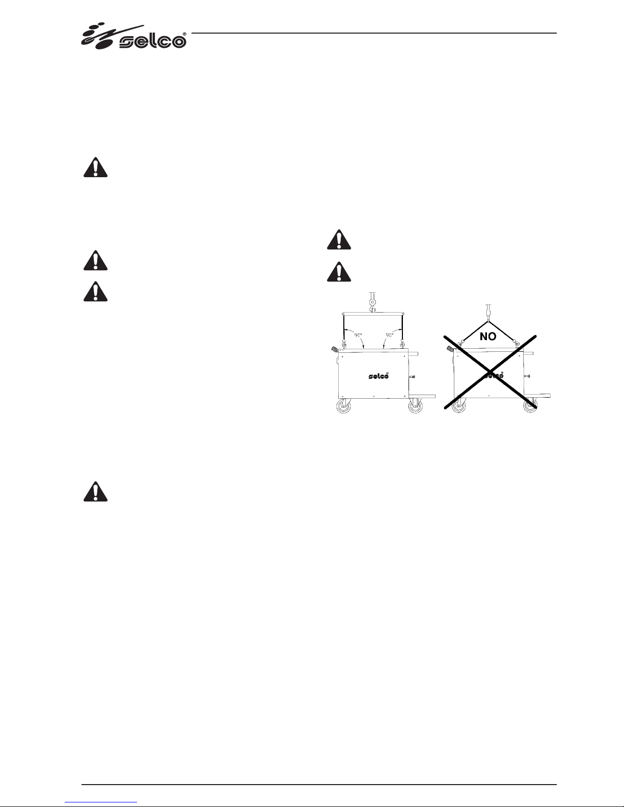
1.2.4 Attention: method of lifting
To correctly lift the machine, follow the diagram in Figure 1.
Avoid absolutely lifting it at any angle different from 90°.
Never lift the machine in the way shown in figure 2: this
could damage the eyebolts.
Be careful not to cause damage during lifting.
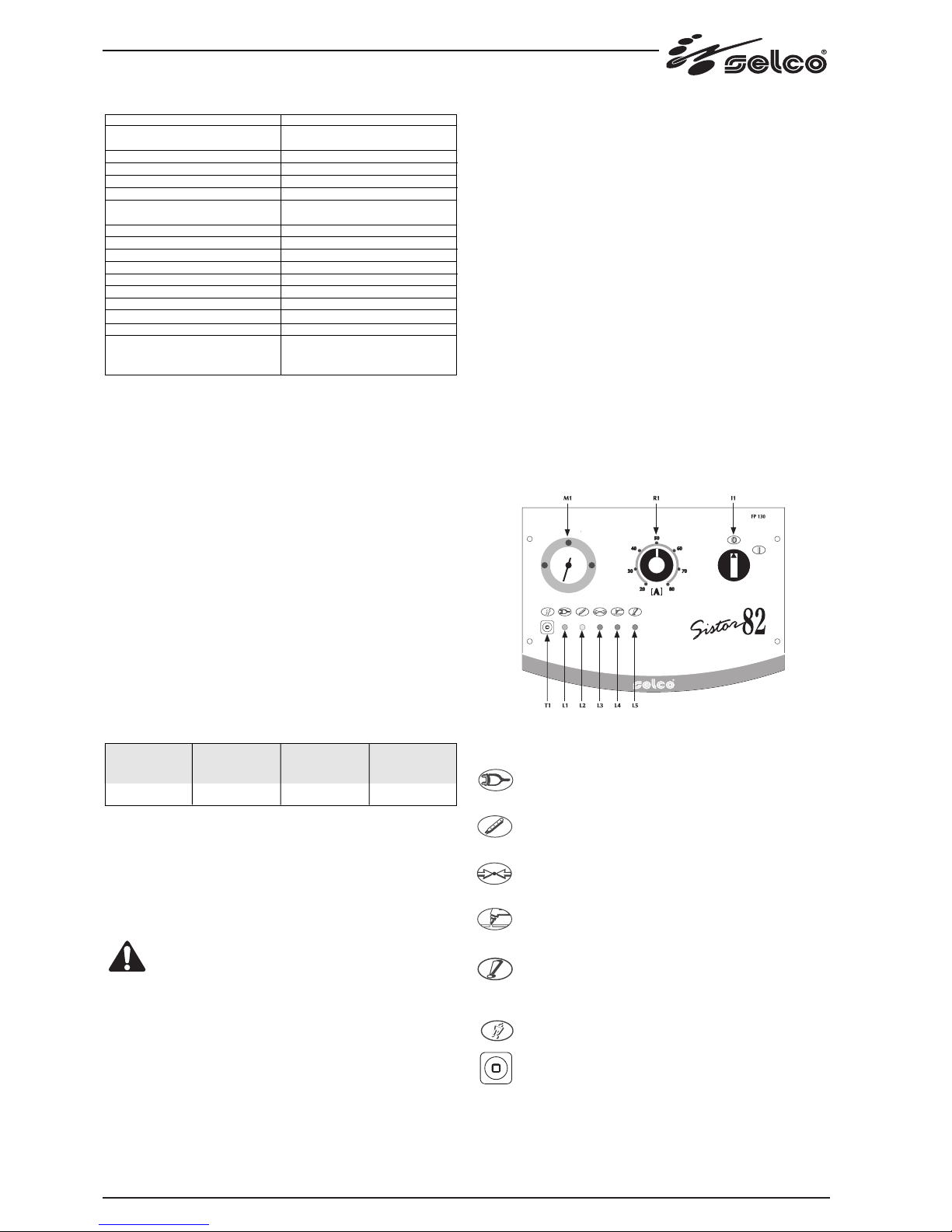
2.0 INTRODUCTION
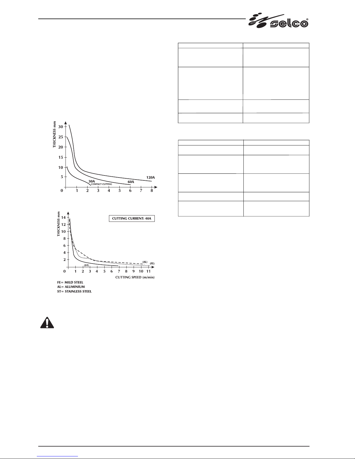
Sistor 82 is a generator for plasma cutting, which is ideal for medium
and heavy structural work.
Sistor 82 uses compressed air as its only gas source, which can be sup-
plied from a normal compressor or from a suitably sized centralized
plant. It is able to carry out, cheaply, cuts of a high quality up to a thick-
ness of 25 mm in carbon steel.
The current is stable, precise and unaffected by variations in the supply
voltage, the height of the cutting arc, the progression speed and the
thickness of the metal to be cut.
This high performance is made possible thanks to the use of state-of-
the-art technology, which employs the high commutation speed pos-
sible with the latest electronic components.
There are safety systems that cut off the power circuit when the opera-
tor comes into contact with live parts of the machine, as well as con-
trols to reduce the wear on the electrode and nozzle at the moment of
striking the cutting arc. The ignition of the cutting arc takes place with
the use of a high frequence voltage discharge, that becomes automati-
cally cut off when the operation is complete, thus limiting the emission
of radio interference in the rest of the cutting process.
1.1.7 Precautions against risks connected with the use of com-
pressed air
Connect the air supply to the coupling provided, making sure pressu-
re is at least 6 bars (0.6 MPa) with a minimum flow rate of 200 l/min.
If the air supply comes from pressure reducer of a compressor or a cen-
tral system, the reducer must be set to the maximum outlet pressure
that must not, however, exceed 8 bars (0.8 MPa). If the air supply
comes from a compressed air canister it must be equipped with a pres-
sure regulator.
A compressed air canister must never be directly coupled
to the machine pressure reducer. Pressure might exceed the
capacity of the reducer which might consequently explode.
1.2 ELECTROMAGNETIC COMPATIBILITY (EMC)
1.2.1 General information
This device is built in compliance with the indications contained in the
harmonized standard EN50199, which the operator must refer to for
the use of this apparatus.
Install and use the apparatus keeping to the instructions
given in this manual.
This device must be used for professional application only,
in industrial environments. It is important to remember
that it may be difficult to ensure the electromagnetic com-
patibility in other environments.
1.2.2 Installation, use and area examination
- The user is responsible for the installation and use of the equipment
according to the manufacturer's instructions.
lf any electromagnetic disturbance is noticed, the user must solve the
problem, if necessary with the manufacturer's technical assistance.
- In any case electromagnetic disturbances must be reduced until
they are not a nuisance any longer.
- Before installing this apparatus, the user must evaluate the potential
electromagnetic problems that may arise in the surrounding area,
considering in particular the health conditions of the persons in the
vicinity, for example of persons with pacemakers or hearing aids.
1.2.3 Emission reduction methods
MAINS POWER SUPPLY
This device must be connected to the supply mains accor-
ding to the manufactures instructions.
In case of interference, it may be necessary to take further precautions
like the filtering of the mains power supply.
lt is also necessary to consider the possibility to shield the power supply
cable.
MAINTENANCE
This device needs routine maintenance according to the manufacturer's
instructions.
When the equipment is working, all the access and operating doors
and covers must be closed and fixed.
This device must not be modified in any way.
WELDING AND CUTTING CABLES
The welding (cutting) cables must be kept as short as possible, positio-
ned near one another and laid at or approximately at ground level.
EQUIPOTENTIAL CONNECTION
The earth connection of all the metal components in the welding (cut-
ting) installation and near it must be taken in consideration.
However, the metal components connected to the workpiece will in-
crease the risk of electric shock for the operator, if he touches said me-
tal components and the electrode at the same time.
Therefore, the operator must be insulated from all the earthed metal
components.
The equipotential connection must be made according to the national
regulations.
Figura 1
Correct lifting method
Figura 2
Incorrect lifting method