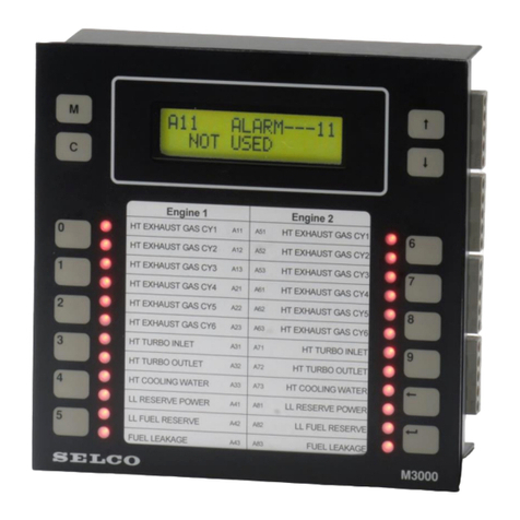
Sel M4200 User manual

SELCO ∙Betonvej 11 ∙DK-4000 Roskilde ∙Phone: +45 7026 1122 ∙Fax: +45 7026 2522 ∙www.selco.com
Alarm Monitor - M4200
User manual
Revision: 07.03.2017

M4200 - User manual
Revision: 07.03.2017 Page 1
Table of contents
TABLE OF CONTENTS......................................................................................................................................................1
INTRODUCTORY NOTES.................................................................................................................................................3
LAYOUT.................................................................................................................................................................................3
FACILITIES ON THE FRONT .................................................................................................................................................... 3
FACILITIES ON THE REAR ...................................................................................................................................................... 3
FUNCTION.............................................................................................................................................................................4
FUNCTION DIAGRAM.............................................................................................................................................................4
INSTALLATION INSTRUCTIONS.................................................................................................................................. 5
SINGLE UNIT..........................................................................................................................................................................5
MULTIPLE UNITS ...................................................................................................................................................................6
Synchronisation................................................................................................................................................................6
RELAY OUTPUTS....................................................................................................................................................................7
Normally de-energized..................................................................................................................................................... 7
Normally energized..........................................................................................................................................................8
Load capacity...................................................................................................................................................................9
OPEN COLLECTOR OUTPUTS ...............................................................................................................................................10
Normally de-energized...................................................................................................................................................10
Normally energized........................................................................................................................................................10
Load capacity.................................................................................................................................................................10
NC INPUTCONTACTS ..........................................................................................................................................................11
Example..........................................................................................................................................................................11
CABLE MONITORING...........................................................................................................................................................12
Example..........................................................................................................................................................................12
Input reference...............................................................................................................................................................12
Normally open inputs.....................................................................................................................................................12
Normally closed inputs..................................................................................................................................................12
Inputs in general.............................................................................................................................................................12
INPUTREFERENCE...............................................................................................................................................................13
Example..........................................................................................................................................................................13
PROGRAMMING BY SWITCHES.................................................................................................................................14
ROTARY SWITCH -OPERATIONALPRINCIPLE .....................................................................................................................14
DIP SWITCHES -OPERATIONAL PRINCIPLE..........................................................................................................................15
Factory default - dip switches........................................................................................................................................15
Factory default –all settings.........................................................................................................................................15
Set button........................................................................................................................................................................16
Acknowledge LED..........................................................................................................................................................16
DIP SWITCH -PROGRAMMING.............................................................................................................................................17
Input settings..................................................................................................................................................................17
General settings..............................................................................................................................................................19
WINDOWS®SOFTWARE................................................................................................................................................21
LOCATE HYPERTERMINALON THE PC..............................................................................................................................21
INSTALLINGHYPERTERMINAL...........................................................................................................................................22
WIRING................................................................................................................................................................................22
CREATE ANEW CONNECTION .............................................................................................................................................23
ASCI settings..................................................................................................................................................................24
SAVE CONNECTION .............................................................................................................................................................25
INTRODUCTION TO MICROSOFT®HYPERTERMINAL .........................................................................................................25
Icon explanation.............................................................................................................................................................25

M4200 - User manual
Revision: 07.03.2017 Page 2
PROGRAMMING BY PC..................................................................................................................................................26
READ CONFIG ......................................................................................................................................................................26
SYSTEM PARAMETERS......................................................................................................................................................... 27
Channel functions..........................................................................................................................................................27
Input contact type...........................................................................................................................................................27
Input reference...............................................................................................................................................................27
Cable monitoring...........................................................................................................................................................28
Input delay......................................................................................................................................................................28
LED colour.....................................................................................................................................................................28
Block function 1..............................................................................................................................................................29
Block function 2..............................................................................................................................................................29
Alarm 1 (output relay 1) ................................................................................................................................................29
Alarm 2 (output relay 2) ................................................................................................................................................30
Siren (relay)....................................................................................................................................................................30
Output 1 - 4.....................................................................................................................................................................30
Output relay 1 (contact)*...............................................................................................................................................31
Output relay 2 (contact)*...............................................................................................................................................31
Siren relay (contact)*.....................................................................................................................................................31
Output 1 –4 (contact)*..................................................................................................................................................31
Output relay 1 (signal)*.................................................................................................................................................31
Output relay 2 (signal)*.................................................................................................................................................31
Siren relay (signal)*.......................................................................................................................................................31
Unblock delays...............................................................................................................................................................32
Reset functions................................................................................................................................................................32
Factory default...............................................................................................................................................................32
SAVE SETTINGS IN A TEXTFILE...........................................................................................................................................33
LOAD SETTINGS FROM A TEXT FILE ....................................................................................................................................34

M4200 - User manual
Revision: 07.03.2017 Page 3
Introductory notes
This manual describes installation and operating instructions together with dip switch configuration of the
Alarm Monitor M4200.
This manual also includes information about how to configure the product, using the included RS232 cable
and a Windows®PC running Microsoft®HyperTerminal.
Layout
Below is a description of the facilities on the front and the rear of the unit.
Facilities on the front
Facilities on the rear
Output terminals. 4 open collector outputsfor
remote control ofexternal lamps or relays.
Sync.Usedfor synchronization of flashingLEDs
onmultiple M4200 units.
8 LEDs, onefor each input
terminal. By programmingit
is possible to change the
colourindividually for each
LED, into red, greenor
yellow.
Whenreset button is pushed,
all relay outputs gooff and
LED status change from
flashing tosteady mode
Whentest button is pushed, all LEDs
showsteady light. Hold down thebutton
and test status willchange from redinto
green and into yellow.
Keep down the button and dimming of all
LEDs can bedone in 8 consecutive levels.
Green LED. Active
when power is on.
+REF and GND.Reference toinputs.+REFis
thesameas positive power reference.GNDis
galvanically separated fromthe negative power
reference.
Reset, test andblock functionalityforremote
activation.GND is common reference.
RS232interface. Used for connection with PC.
Power. Terminal 24ispositivereference.
Terminal 26isnegativereference.Terminal 25 is
not in use.
Output relays. Alarm1 isdefaultactivated when
inputsareactive.It is possible toset up activation
mode for both alarm1and 2.
Sirenrelay. Default activated when inputs are
active. It ispossibletoset up activationmode for
the sirenrelay.
Input terminals. Usedforconnectionofpotential
freecontacts.Both NO andNC contacts are
supported.
10 channel rotary switch. Usedfor
switch configurationof theunit:
0: Operationalmode
1 -8: Set input 1 -8
9: Set generalfunctions
Acknowledge LED.
Indicates thatprogramming
bysetbutton isaccepted.
8 dip switches. Usedfor configurationof
theunit. Namedindocumentationas 1-1
to1-8.
Set button. Used for
acceptof rotary and dip
switch settings.
8 dip switches. Usedfor configurationof
theunit. Namedindocumentationas 2-1
to2-8.

M4200 - User manual
Revision: 07.03.2017 Page 4
Function
The Alarm Monitor M4200 provides the possibilityof monitoring 8 individual processes. All inputs will accept
any combination of NO or NC contacts.
It is possible to programme each input, e.g. to activate the siren relay, the two alarm relays or the four open
collector outputs. The delays for the inputs can be selected between 25 milliseconds and 60 seconds.
With the default configuration on M4200, the alarm scenario will unfold as shown in Figure 1.
Figure 1. Function diagram, default scenario.
Function diagram
When alarm input is activated, the LED goes flashing, alarm relay 1 and the siren relay goes ON.
When reset button is activated, the LED goes steady and the siren goes OFF.
When alarm input is de-activated, LED goes OFF, together with alarm 1.

M4200 - User manual
Revision: 07.03.2017 Page 5
Installation instructions
This section contains information about how to install the alarm monitor.
Single unit
Figure 2 shows the default connection of the input and output terminals on the alarm monitor. Input terminals
1 - 8 are connected to +REF OUT (positive supply) via potential free contacts.
Reset, test and block terminals are connected to GND via potential free contacts.
Lamps are connected to the outputs; the lamps are supplied from same source as the unit. Terminal26 is
connected to ÷ (negative supply).
Figure 2. Wiring example, single unit (default connection).

M4200 - User manual
Revision: 07.03.2017 Page 6
Multiple units
Figure 3 shows the default connectionof the input andoutput terminals on two M4200 units. Input terminals
1 - 8 are connected to +REF OUT (positive supply) on one of the units via potential free contacts.
Test terminals are connected to GND on both units via potential free contacts (test and block terminals can
be connected bythe samemethod).
Lamps are connected to the outputs; the lamps are supplied from same source as the units. Terminal 26 is
connected to ÷ (negative supply).
Figure 3. Wiring example,multiple units with external reset (default connection).
Synchronisation
If multiple units are positioned side by side it can be desirable that all LEDs, on all the units are flashing with
the same speed rate.
If all Sync terminals (23) on all the multiple units are connected with each other, all LEDs will operate with the
same speed rate.
No further configuration is needed. The Sync functionality has no other importance than providing visual
continuity.

M4200 - User manual
Revision: 07.03.2017 Page 7
Relay outputs
The alarm monitor has 3 output relays; all of them can be activated by any of the 8 alarm inputs. The relays
can work as de-energized or energized, when the power is on the alarm monitor. The alarm monitor is
delivered with all output relays operating in normallyde-energized mode.
This section contains information about the 2 principles and how and when to use them.
This section only contains information about the relay outputs (terminal 27 - 35). The examples in this
section are based on the siren relay, but all of the 3 output relays can be used individuallywith the same
functionality.
Normally de-energized
Figure 4 shows the default connection of the output terminals on the alarm monitor.
The alarm monitor is delivered with all output relays operating in normally de-energized mode. This means
that the relay stays in the same position, whether the power is on or off.When an incoming alarm activates
the relay, the position will change from terminal 33 to 35 (siren relay).
The output relay is supplied from same source as the unit. The siren is connected to the output relay.
Terminal 26 and the siren are connected to ÷ (negative supply).
NOTE:
Regarding load capacity for the output relays, please refer to the section Load capacity on page 9in this
manual.
Figure 4. Wiring example, normally de- energized relay (default connection).

M4200 - User manual
Revision: 07.03.2017 Page 8
Normally energized
Figure 5 shows the connection of the output terminals when the relay is programmed to be normally
energized.
It is possible to programme each of the output relays to operate individually as normally energized. This
means that the relay changes position from terminal 33 to terminal 35 (siren relay) when the power is
switched on.
When an incoming alarm activates the relay, the position will change from terminal 35 to 33 (siren relay).
The same scenario will appear if the supplyvoltage disappears from the alarm monitor. This is a big
advantage when alarm is needed, if breakdown of the alarm system occurs.
If supply voltagedisappears from the alarm monitor and alarm is needed, it is very important to use another
supply unit for the output relays, than used for the supply voltage of the alarm monitor.
The output relay is supplied from another source than the alarm monitor.The siren is connected to the
output relay. The siren is connected to another ÷ (negative supply) than that of the alarm monitor.
NOTE:
Regarding load capacity for the output relays, please refer to the section Load capacity on page 9.
To use any of the three output relays as normally energized, programming is needed. For further information
about programming please refer to the section Programming by switches on page 14 or Programming by
PC on page 26.
Figure 5. Wiring example, normally energized relay.

M4200 - User manual
Revision: 07.03.2017 Page 9
Load capacity
The output relays are able to manage any kind of resistive load. The load capacity depends on whether AC
or DC voltage is connected to the relay.
Below is listed the maximum load capacity for AC and DC voltage respectively:
Max. AC load:
250VAC / 4A
Max. DC load:
Readings of DC load
capacity curve above:
VDC
Ampere
10
4
12
4
24
4
48
2
110
0,5
300
0,1

M4200 - User manual
Revision: 07.03.2017 Page 10
Open collector outputs
The alarm monitor has 4 open collector outputs; all of them can be activated byanyof the 8 alarm inputs.
These outputs are able to work as energized or de- energized, similar to the output relays. This section
contains information about the 2 principles and how to use them.
Figure 6 shows the connection diagram of the output terminals (terminal 19 - 22) on the alarm monitor.
Figure 6. Wiring example, open collector outputs.
Normally de-energized
The alarm monitor is delivered with all open collector outputs operating as normally de-energized.
This means that the output has no reference whether power is on or off. When an incoming alarm activates
the output, status is changing to negative (÷) reference.
Normally energized
It is possible to programme each of the open collector outputs to operate individually as normally energized.
This means that the output changes to negative (÷) reference when the power is switched on.When an
incoming alarm activates the output, status is changing and the negative (÷) reference disappears.
Load capacity
Maximum load capacity for the open collector outputs is 60VDC / 700mA.

M4200 - User manual
Revision: 07.03.2017 Page 11
NC input contacts
IMPORTANT: It is only recommended to use the example below if the alarm monitor is still in factory default
mode. If there is any possibility that the alarm monitor has been programmed previously, please refer to the
section Factory default - dip switches on page 15.
Example
Input 1 - 8 accept any combination of NO or NC contacts. Default configuration only supports NO contacts. If
NC contacts are used, please follow the example below regarding input 1, terminal 1:
1. Set rotary switch in position 1(acknowledge LED change into red colour).
2. Set dip switch 1-1 to On (NC contact).
3. Press Set button until Acknowledge LED shortly turns into green light.
4. Release Set button.
Now it is possible to connect input 1 as shown in Figure 7:
Figure 7. Wiring example, NC input
If NC contacts are needed on any other input channels, please select the input number on the rotary switch
and follow step 3 and 4 above.

M4200 - User manual
Revision: 07.03.2017 Page 12
Cable monitoring
Cable monitoring provides extra securityto the alarm system. Cable faults are indicated with short flashing
pulses on the corresponding alarm channels. Cable fault indications will beoverridden by activation of input
alarmsandindicated with normalalarm flash or steady light indication.
IMPORTANT: It is only recommended to use the example below if the alarm monitor is still in factory default
mode. If there is any possibility that the alarm monitor has been programmed previously, please refer to the
section Factory default - dip switches on page 15.
Example
The example belowrefer to input 1, terminal 1:
1. Set rotary switch in position 1(acknowledge LED change into red colour).
2. Set dip switch 1-3 to On (Cable monitoring).
3. Press Set button until Acknowledge LED shortly turns into green light.
4. Release Set button.
Now it is possible to connect input 1 as shown in Figure 8 and
Figure 8. Wiring example,cable monitoringon input 1
If cable monitoring is needed on any other input channel, please select the input number on the rotary switch
and follow step 3 and 4 above.
Notice that two measuring resistors (1 in series and 1 in parallel) are needed for each of the inputs operating
with cable monitoring. It is very important that both resistors are mounted close to the input contact.
Input reference
In the example above + REF OUT (9) is used as input reference. It is possible to use both + Ref (9) and
GND Ref (10) with cable monitoring without further configuration.
Normally open inputs
The resistor in parallel is monitoring cable break.
The resistor in serial is monitoring short circuit.
Normally closed inputs
The resistor in parallel is monitoring short circuit.
The resistor in serial is monitoring cable break.
Inputs in general
However the input is operating as, normally open or normallyclosed, same size of resistors is used.

M4200 - User manual
Revision: 07.03.2017 Page 13
Input reference
IMPORTANT: It is only recommended to use the programming example below if the alarm monitor is still in
factorydefault mode. If there is any possibility that the alarm monitor has been programmed before, please
refer to the section Factory default - dip switches on page 15.
Example
It is possible to set up input 1-8 individually to positive or negative reference. Default configuration is positive
reference via the terminal +REF OUT.
If negative reference is needed, please follow the example below regarding input 1, terminal 1:
1. Set rotary switch in position 1(acknowledge LED change into red colour).
2. Set dip switch 1-2 to Off (GND reference).
3. Press Set button until Acknowledge LED shortly turns into green light.
4. Release Set button.
Now it is possible to connect input 1 as shown in Figure 9:
Figure 9. Wiring example, GND
If GND reference is needed on any other input channel, please select the input number on the rotary switch
and follow step 3 and 4 above.

M4200 - User manual
Revision: 07.03.2017 Page 14
Programming by switches
There are two ways of programming the alarm monitor; by dip switches on the rear of the unit or by any
standard ANSI compatible terminal application e.g. Microsoft®HyperTerminal (which is supplied with the
Windows®operating system) or any other ANSI terminal.
When using a standard ANSI compatible terminal application, the configuration is done through a PC, via the
special RS232 cable, which is delivered with the M4200 unit.
This section only contains information about programming bydip switches.
Switches
All switches needed for programming are located on the rear of the alarm monitor. There is 1 rotaryswitch
with 10 channels for mode selection and 2 rows of dip switches with each 8 dip switches for choosing
different programming facilities.
Below is a description of the functions, both on the rotaryswitch and the dip switches.
Rotary switch - operational principle
Below is an explanation of the different modes on the rotary switch. Figure 10 illustrates the different modes
schematically.
Position “0” is operational mode. This mode is default selected and means that the alarm monitor is running
in alarm mode.
Position 1 –8 is programming mode for each of the input channels. Programming functions into channel 1,
set the rotary switch in position 1 etc.
Position 9 is programming mode for general functions, such as block, delayand reset functions.
Position
Mode
0
Operational (alarm)
1
Set input 1
2
Set input 2
3
Set input 3
4
Set input 4
5
Set input 5
6
Set input 6
7
Set input 7
8
Set input 8
9
Set general functions
Figure 10. Modes onrotary switch.

M4200 - User manual
Revision: 07.03.2017 Page 15
Dip switches - operational principle
There are 16 dip switches spread on 2 rows with 8 in each row. Each dip switch has 2 positions; ON and
OFF (2 functions per dip switch).
The functions of each dip switch depend on the position of the rotary. This means that 2 × 16 (on/off)
different settings are available on each of the 9 positions on the rotary switch (no programming facilities are
available when the rotary switch is in position 0, operational mode).
When the rotaryswitch is in position 1 –8, each dip switch has the same functions because the same
functions are needed on each input channel.
Factory default - dip switches
Figure 11 shows how all the dip switches are set, when the alarm monitor leaves the SELCO factory. Before
starting any programming session on the alarm monitor, it is recommended to set all dip switches as shown
in Figure 11.
The reason is that when saving is done by the set button, all settings will be saved even though only a few
dip switch positions have been changed.
Top row of dip switches (1)
ON
X
X
OFF
X
X
X
X
X
X
1.1
1.2
1.3
1.4
1.5
1.6
1.7
1.8
Bottom row of dip switches (2)
ON
X
X
OFF
X
X
X
X
X
X
2.1
2.2
2.3
2.4
2.5
2.6
2.7
2.8
Figure 11. Dipswitch settings (factory default).
Factory default –all settings
It is possible to return all settings on the alarm monitor into factorydefault by 1 operating cycle:
1. Set the rotary switch in position 0.
2. Press the button “Set” (the colour of the “Ack” LED changes into red light).
3. Hold “Set” button down in 5 seconds.
4. The colour of the “Ack” LED changes into green light.
5. Release the “Set” button.
Now all settings are returned to factory default. It is still necessary to set up all dip switch contacts manually
(please refer to the previous section in this manual).
8 dip switches (1. row). Named in
documentationas 1.1to 1.8.
8 dip switches (2. row). Named in
documentationas 2.1to 2.8.

M4200 - User manual
Revision: 07.03.2017 Page 16
Set button
The set button is positioned on the rear of the alarm monitor, below the dip switches.
This push button is used for accept of rotary and dip switch settings. Set button is related to the rotary switch,
which means that all dip switch settings made, in the selected position of the rotary switch, will be saved
when the set button is pushed.
IMPORTANT
Itis veryimportant to check theposition of all16 dip switches before set button is pushed.
Acknowledge LED
Acknowledge LED is positioned on the rear of the alarm monitor, beside the save button.
When the rotaryswitch is in programmingmode (Position 1 - 9) the LED gives a constant red light.
When set button is pushed and held down, the LED will flash 2 times and change into green light until set
button is released. Green light indicates that saving the settings done byset button is accepted.

M4200 - User manual
Revision: 07.03.2017 Page 17
Dip switch - programming
This section lists all possible settings that can be done by the switches on the rear of the alarm monitor.
Before starting the programming session please read the previous section Dip switches - operational
principle on page 15.
Input settings
Before programming the input settings please select the position number on the rotary switch (position 1 - 8).
In the table below the default settings are marked with bold type.
Switch row 1
Function
Switch setting
Switch setting
Switch setting
Description
Input type
SW1.1
OFF
Normally Open
ON
Normally Closed
Input reference
SW1.2
OFF
GND
ON
+VREF OUT
Cable monitoring
SW1.3
OFF
Inactive
ON
Active
Input Delay
SW1.4
SW1.5
SW1.6
OFF
OFF
OFF
25 ms
OFF
OFF
ON
500 ms
OFF
ON
OFF
1 s
OFF
ON
ON
2 s
ON
OFF
OFF
5 s
ON
OFF
ON
10 s
ON
ON
OFF
30 s
ON
ON
ON
60 s
LED Colour
SW1.7
SW1.8
OFF
OFF
No light
OFF
ON
Red
ON
OFF
Green
ON
ON
Yellow

M4200 - User manual
Revision: 07.03.2017 Page 18
Switch row 2
Function
Switch setting
Description
Block1
SW2.1
OFF
No effect
ON
Block
Block2
SW2.2
OFF
No effect
ON
Block
Alarm1
SW2.3
OFF
No effect
ON
Activate
Alarm2
SW2.4
OFF
No effect
ON
Activate
Siren
SW2.5
OFF
No effect
ON
Activate
Out1
SW2.6
OFF
No effect
ON
Activate
Out2
SW2.7
OFF
No effect
ON
Activate
Out3
SW2.8
OFF
No effect
ON
Activate

M4200 - User manual
Revision: 07.03.2017 Page 19
General settings
Before programming the general settings please select the position number on the rotary switch (position 9).
In the table below the default settings are marked with bold type.
Switch row 1
Function
Switch setting
Description
Alarm Relay 1
SW 1.1
OFF
Normally De-energized
ON
Nomally Energized
Alarm Relay 2
SW 1.2
OFF
Normally De-energized
ON
Nomally Energized
Siren Relay
SW 1.3
OFF
Normally De-energized
ON
Nomally Energized
Open Collector 1
SW 1.4
OFF
Normally De-energized
ON
Normally low
Open Collector 2
SW 1.5
OFF
Normally De-energized
ON
Normally low
Open Collector 3
SW 1.6
OFF
Normally De-energized
ON
Normally low
Open Collector 4
SW 1.7
OFF
Normally De-energized
ON
Normally low
Spare
SW 1.8
OFF
No effect
ON
No effect
Table of contents
Other Sel Security System manuals