Mangelmann Elektrotechnische
Holtumsweg 13, D-47652 Weeze, Tel. +49 2837/9134-0, Fax. +49 2837/1444
www.uni-geraete.de info@uni-geraete.de
Seite 6
/ 14 TM 4021
220.100.038-18
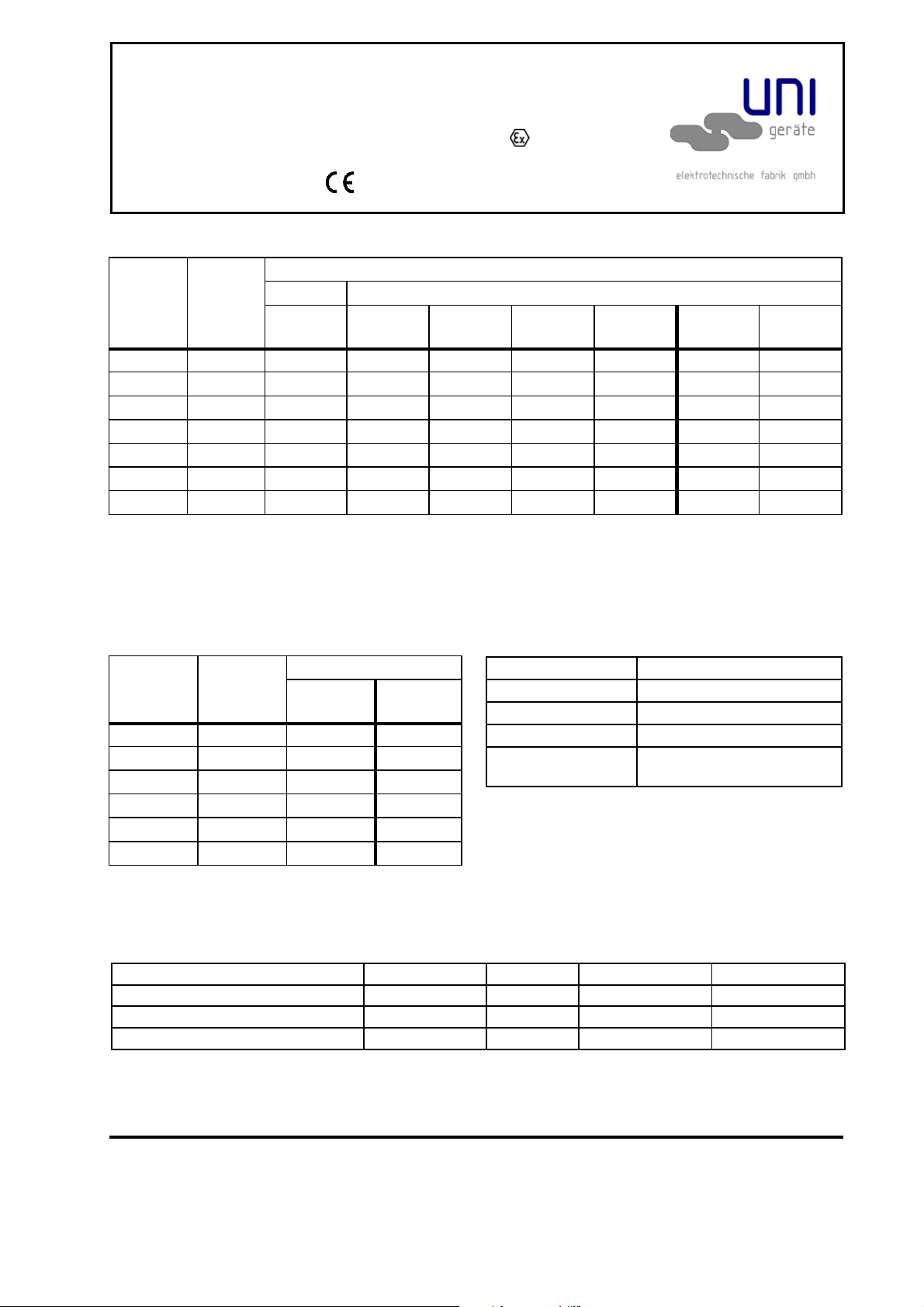
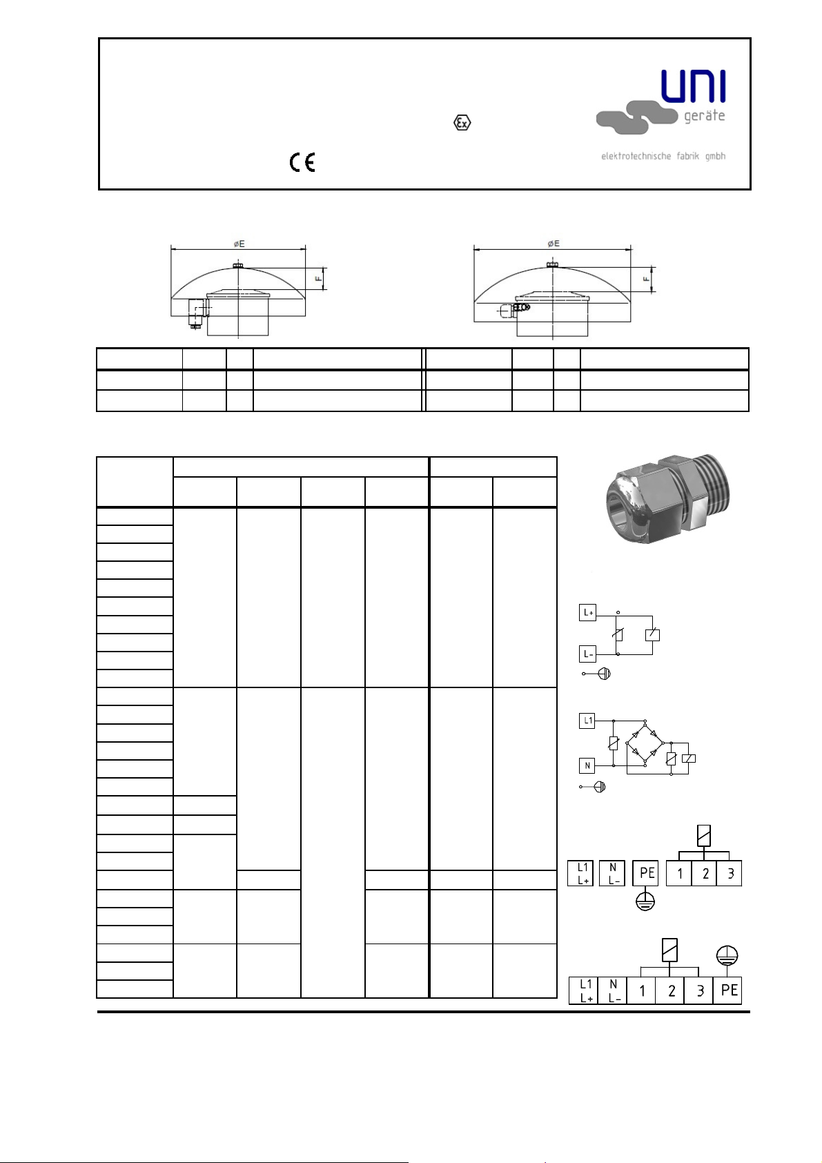
Solenoid drive
Series MG.., MG..A, MG..A..C (no explosion protection)
Series MG..Xn, MG..A..Xn, MG..A..C..Xn (with - protection
for the intended use in zone 2) in accordance with
2014/34/EU (ATEX 95))
T
yp
M
G...
P
W
Nominal current A
24
V
DC
230
VA
C
010-A5 200/20 8,3/0,8 1,2/0,9
012-A5 200/20 8,3/0,8 1,2/0,9
014-A5 200/20 8,3/0,8 1,2/0,9
016-A5 200/20 8,3/0,8 1,2/0,9
018-A5 200/20 8,3/0,8 1,2/0,9
019-A5 200/20 8,3/0,8 1,2/0,9
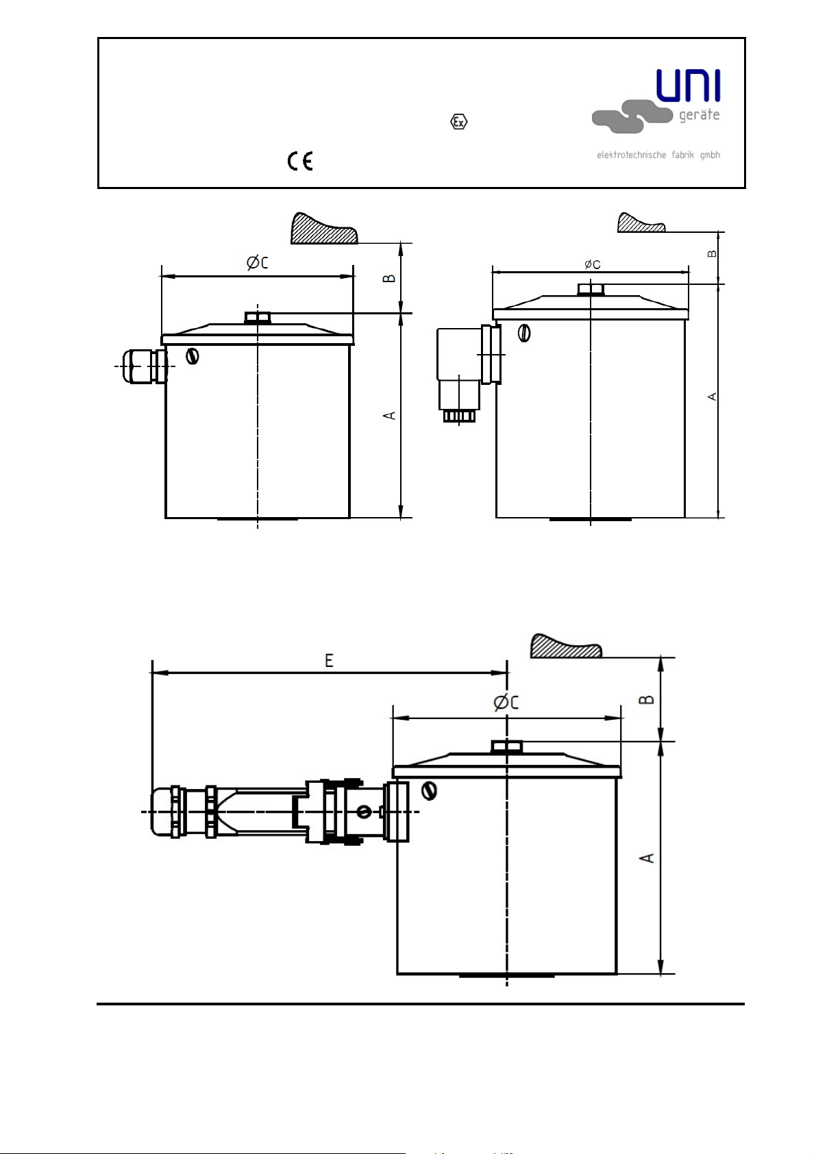
Solenoid drive MG...A / MG...A...Xn with integrated control TS900, TS1500
T
yp
M
G..A..
P
W
Nominal current
A*
TS 900 TS 1500
24
V
DC
110
V
DC
220
VDC
230
V
DC
240
VDC
110
VA
C
230
VA
C
016-A 720/70 30/2,9 6,5/0,6 3,3/0,3 3,1/0,3 3,0/0,3 6,5/0,6 3,1/0,3
018-A1 900/70 38/2,9 8,2/0,6 4,1/0,3 3,9/0,3 3,8/0,3 8,2/0,6 3,9/0,3
018-A2 1200/70 - 11/0,6 5,5/0,3 5,2/0,3 5,0/0,3 11/0,6 5,2/0,3
019-A1 1200/120
- 11/1,1 5,5/0,6 5,2/0,5 5,0/0,5 11/1,1 5,2/0,5
019-A2 1500/90 - 14/0,8 6,8/0,4 6,5/0,4 6,3/0,4 14/0,8 6,5/0,4
019-A5.3
400/20 17/0,9 3,6/0,2 1,8/0,09 1,7/0,09 1,7/0,08 3,6/0,2 1,7/0,09
019-A5.4
400/50 17/2,1 3,6/0,5 1,8/0,23 1,7/0,2 1,7/0,2 3,6/0,5 1,7/0,22
*Amb.-temp. 20°C at 100% duty cycle stationary warmed up (Amb.-temp. 20°C at 0% duty cycle – switch
on moment / values x factor 1,25)
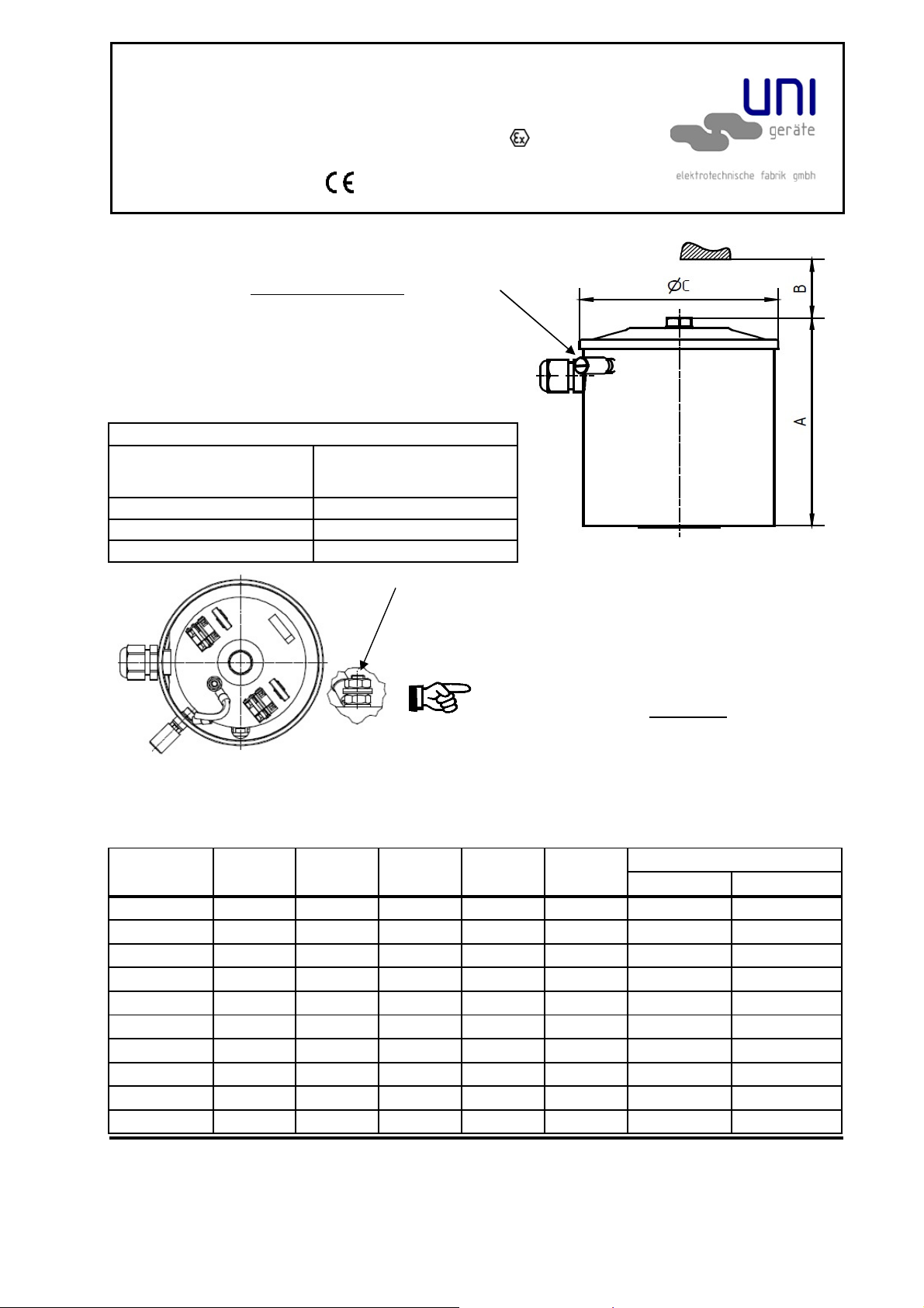
Solenoid drive MG...A5 / MG...A5...Xn
With integrated control TS200
Switching Frequenzy:
*
Amb.-temp. 20°C at 0% duty cycle – switch on moment
Soelnoid valve control
Solenoid valvce control TS 200 TS 800 TS 900 / 1500 RKS 5-1500 / 5-4000
max. switching capacity Watt 200 800 900/1500 1500/4000
Switch over time Sec. 1,5 40(*) 3 3
For opening delay Sec. - - 10 10
(*) Charging time
switchings / hour Solenoid drive MG
1000 004 - 020
20 016A - 020A
600 010A5 - 019A5
20 016A5C6, 019A5C6 ;
016A5.2C6, 019A5.2C9