Select Insect-O-Cutor SE22 User manual

13
SELECT
SELECT
SELECT
High performance combined with clean aesthetic lines, the Select range is
ideal for food preparation areas. The deep catch tray ensures that insects
are easily contained within the unit.
SE44
ROOM COVERAGE
80 z 160 m²
APPLICATION
Industrial
Backroom
PRODUCT CODE
SE23
DESCRIPTION
SE22, 22 Watt, Stainless
DIMENSIONS (MM) H x W x D
140 x 376 x 420
COVERAGE (M²)
80
TUBES
1 X TGX22
WEIGHT (KG)
5.6
PRODUCT CODE
SE22
DESCRIPTION
SE22, 22 Watt, White
DIMENSIONS (MM) H x W x D
140 x 376 x 420
COVERAGE (M²)
80
TUBES
1 X TGX22
WEIGHT (KG)
5.6
PRODUCT CODE
SE45
DESCRIPTION
SE44, 44 Watt, Stainless
DIMENSIONS (MM) H x W x D
140 x 740 x 490
COVERAGE (M²)
160
TUBES
2 X TGX22
WEIGHT (KG)
7.5
PRODUCT CODE
SE44
DESCRIPTION
SE44, 44 Watt, White
DIMENSIONS (MM) H x W x D
140 x 740 x 490
COVERAGE (M²)
160
TUBES
2 X TGX22
WEIGHT (KG)
7.5
SE22
High performance removable killing grid allows the unit to be cleaned easily
Tool free maintenance allows easy cleaning and lamp replacement
Patented dual wavelength Synergetic® technology for an increased catch
Simple wall or ceiling
mounting
All metal construction with
stainless steel or white
polyester finish for strength
+ durability
Independently tested and
certified to RoHS and all
relevant European
standards
FEATURES

Please read these instructions carefully and store in a safe
place for future reference.
Select
As part of the Insect-O-Cutor®brand of insect control
products, the Select range is an effective and flexible range of
professional flykillers which utilise highly effective Synergetic®
UV tubes. Constructed from coated mild steel or robust
stainless steel, the Select range can be wall mounted or ceiling
suspended.
Contents of package
- 1 x Insect-O-Cutor flykiller
- 1 x Mains cable (Type X)
- 2 x Wall mounting screws and wall plugs
- 2 x Suspension hooks
- 2 x Suspension chains
- 1 x Backplate
- 1 x High powered UV tube (SE22 - Fitted)
or
- 2 x High powered UV tubes (SE44 - Fitted)
WARNING - THIS APPLIANCE MUST BE EARTHED (CLASS 1)
INSECT CONTROL PRODUCTS
The Select range utilise high powered ultra violet tubes to
attract flying insects and then electrocutes them on a killing
grid, before collecting them in a removable catch tray.
WARNING
The Select range is not to be used by persons with reduced
physical, sensory or mental capabilities, or lack of experience
and training, unless they have been given instruction.
Children should be supervised to ensure they do not play with
the appliance.
If the mains cable is damaged it must be replaced by a
specialist mains cable available from Pelsis Ltd or your supplier.
The Select range must only be used in areas which are free of
dust and any possible explosive vapour mixture, are suitable
for indoor use only and are not suitable for use in barns, stables
and similar locations.
POSITIONING AND GUIDANCE FOR USE
The Select range should ideally be fixed around two meters
above the ground, preferably in the darkest place within the
area to be protected. Do not position the unit close to
windows, skylights or other sources of light, or where it may be
obscured by furniture, doors or other obstacles.
The Select range should ideally be in operation for 24 hours a
day, ensuring your premises are kept free of flying insects.
Insects are most attracted to the Select range units at night
when there is no competition from daylight or other light
sources.
GUARANTEE
The Select range has a five year guarantee and if maintained
as recommended in these instructions should continue to work
for many years*. Use of non-approved consumables may
invalidate the guarantee. *Excludes tubes and starters. Does not cover breakdown due to misuse, incorrect operation
or use in an incorrect application.
INSTALLATION
INSTALLATION SHOULD BE CARRIED OUT BY SERVICE
PERSONNEL ONLY.
Before installation, first remove the plastic tie-wraps that are
securing the removable killing grid in place during transit. The
Select range should be mounted as shown in the mounting
options section of this document. Keep out of reach of
children.
Wall Mounting - Install the supplied wall plugs and screws to
the mounting surface, having first made sure that appropriate
wall plugs are used for specialist mounting materials, such as
plasterboard.
Over time, Ultraviolet light may discolour the mounting
surface. If this would be a problem, mount the supplied
backplate between the back of the flykiller and the wall.
Ceiling Suspension - Fit the suspension hooks to the top of the
unit, by first removing the two top screws, then replacing them
with the suspension hooks in place. Then fix the suspension
chains to the hooks. The Select range should be hung 2 - 3m
from the ground, so if the supplied chains do not allow this,
chains of appropriate length and strength should be sourced.
Once installed into position, use the removable mains lead
and plug to connect the Select range to an appropriate
power supply, as specified on the specification label found on
the flykiller.
CLEANING
CLEANING SHOULD BE CARRIED OUT BY SERVICE PERSONNEL
ONLY, AFTER ENSURING THAT THE UNIT IS DISCONNECTED FROM
THE MAINS SUPPLY.
It is recommended that cleaning is carried out regularly every
month. During cleaning the unit should be thoroughly wiped
down with a damp cloth, removing any build up of dirt.
Ensure the unit is completely dry before reconnecting it to the
power supply. MOUNTING FIXING CENTRES
METHOD SE22 SE44
Wall 150mm 365mm
Suspended 300mm 511mm
Select
Professional Electric Insect Control Select
Mounting Options
Wall
Suspended
Catch Tray & Guard Removal
SPECIFICATION / REPLACEMENT PARTS
Unit SE22 (White) / SE23 (S/S)
Voltage 230V ~ 50Hz
Dimensions(mm) 376 x 140 x 420
Coverage 80 Sq. Meters
Weight 5.6 Kg
Light Output 22W
Tubes 1 x TGX22
Starter 1 x I154
Unit SE44 (White) / SE45 (S/S)
Voltage 230V ~ 50Hz
Dimensions(mm) 592 x 140 x 420
Coverage 160 Sq. Meters
Weight 7.2 Kg
Light Output 44W
Tubes 2 x TGX22
Starter 2 x I154
CATCH TRAY AND FRONT GUARD REMOVAL
To remove the front guard, the catch tray must first be removed as shown to the right. The front guard is
connected to the power supply of the unit via a hidden switch. By removing the front guard the connection
is broken and power is cut to the unit. This ensures safe access to the unit for servicing and cleaning.
NB - WHEN REPLACING THE FRONT GUARD BACK INTO THE SELECT RANGE, ENSURE IT IS PUSHED FULLY INTO
POSITION AND THAT POWER IS RESTORED TO THE UNIT.
NB - THE FRONT GUARD CAN ONLY BE RELEASED ONCE THE CATCH TRAY IS REMOVED
TUBE REPLACEMENT
TUBE REPLACEMENT SHOULD BE CARRIED OUT BY SERVICE PERSONNEL ONLY, AFTER ENSURING THAT THE UNIT IS
DISCONNECTED FROM THE MAINS SUPPLY.
To ensure the efficiency of the Select range in catching flying insects, the UV tube(s) should be replaced
annually. After twelve months the phosphor coating that emits the correct wavelength of UV light has burnt
away and the UV output is diminished substantially.
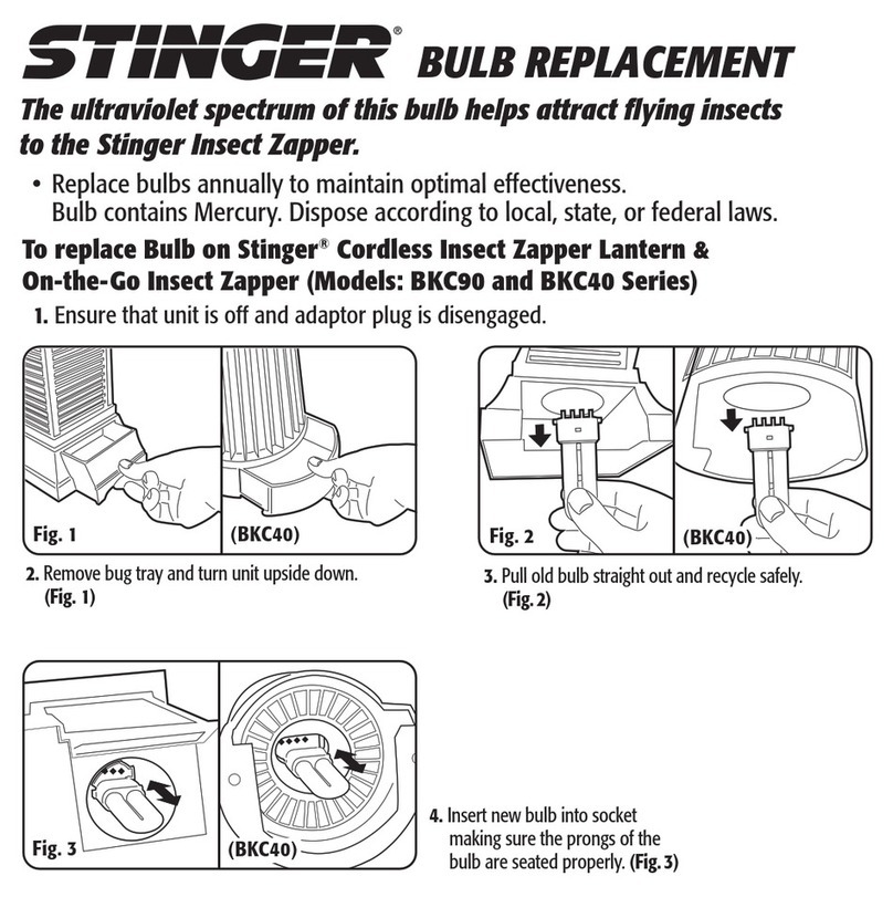
To replace the UV tube(s)…
1. Remove the catch tray.
2. Remove the front guard.
3. Pull the tube away from the tube holder.
2. Pull the tube away from the tube clip.
3. Dispose of the used UV tube in conjunction with local WEEE regulations.
STARTER REPLACEMENT
STARTER REPLACEMENT SHOULD BE CARRIED OUT BY SERVICE PERSONNEL ONLY, AFTER ENSURING THAT THE UNIT
IS DISCONNECTED FROM THE MAINS SUPPLY.
The starters provide an extra spark to initially light the UV tubes. Starters wear out and should be replaced at
the same intervals as the UV tubes.
To replace the starter(s)…
1. Remove the catch tray.
2. Remove the front guard.
3. Rotate the starter anti-clockwise.
4. Pull the starter free from the unit.
KILLING GRID REMOVAL
REMOVAL OF THE KILLING GRID SHOULD BE CARRIED OUT BY SERVICE PERSONNEL ONLY, AFTER ENSURING THAT
THE UNIT IS DISCONNECTED FROM THE MAINS SUPPLY.
To help with servicing and cleaning, the killing grid within the Select range can be removed.
To remove the killing grid...
1. Remove the catch tray.
2. Remove the front guard.
3. Remove the tube(s).
4. Pull the killing grid forward, to release it from the plastic clips.
5. Pull the killing grid down to free it from the unit.
2.
Starter Replacement
2.
Catch Tray & Guard RemovalTube Replacement
2.
12
R3 08/15
C2015
Pelsis Ltd
Information provided on these instructions is modified and
updated from time to time. This is due to the constant
redevelopment of our products. As such, it is not intended that
you should rely on it or that it should form part of any contract.
Sterling House
Grimbald Crag Close
Knaresborough
North Yorkshire
HG5 8PJ UK
T +44 (0)800 988 5359
F +44 (0)1423 863 497
W www.pelsis.com
WEEE Compliance No. WEE/GF0661QR
This manual suits for next models
3