MPPT30-1L-R3
Page 3 of 8
Model:
MPPT30-1L
Unit 2, 110 Station Road, Seven Hills ,NSW, 2147, Australia
Operating Instructions
Please read these instructions before use
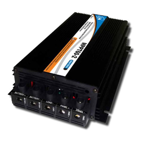
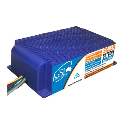
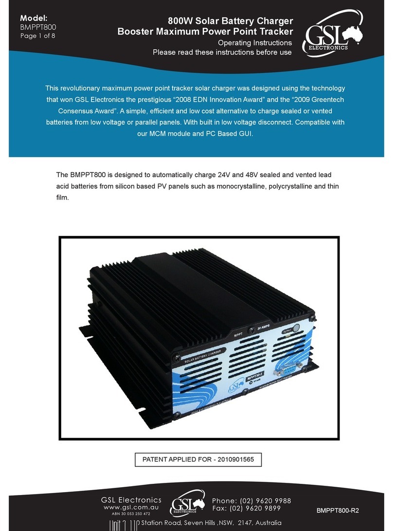
1700W Solar Battery Charger
Maximum Power Point Tracker
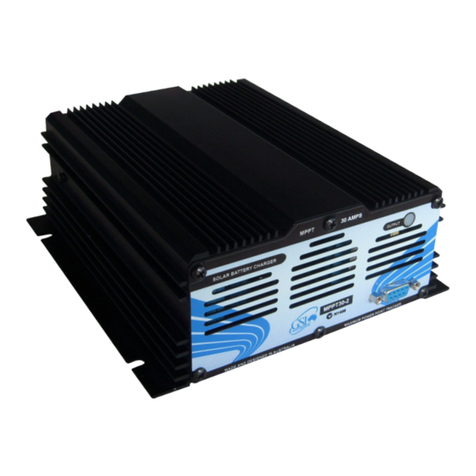
MPPT30-1L General Information:
• Green LED On – Battery OK.
• Green LED Flashing – Battery Low.
• This MPPT is designed to auto detect 12V, 24V or 48V battery systems and select a
suitable charge regime.
• The MPPT 30-1L is shipped set to the default (Nominal) setting which is the safest setting but
if you require Long Life or High Capacity rate, BEFORE wiring the MPPT in, follow the
CHANGING BATTERY TYPE SETTING PROCEDURE..
• The Saturation phase is entered following a low battery condition at dawn and is
maintained for the rest of the day. Otherwise Maintenance voltage is applied.
• Custom oat and absorption voltages and thresholds are possible but minimum orders apply.
• This MPPT has a built in multilevel over temperature protection to improve product reliability
while maximising output power availability.
• The maximum continuous output power is 1700W in 48V systems, 850W in 24V systems
and 425W in 12V systems. The output current is limited to 30A.
• The threshold before the charger will enter a Saturation charge is 13.9V / 27.8V / 55.6V
The MPPT 30-1L is designed to charge LiFePO4from photovoltaic panels. Silicon based
panels such as monocrystalline, polycrystalline and amorphous are suitable.
Important Notes:
• To enhance Battery and Load protection the MIHV or equivalent and a suitable BMS rated to the maximum
panel power and 170% of nominal battery voltage is highly recommended.
• Use only PV Systems with open circuit voltage below 95V and a VMP of 18V for 12V Charging
36V for 24V Charging and 72V for 48V charging.
• This equipment must be installed by qualied personnel only and incorrect wiring can cause
re, injury or death – GSL will accept no responsibility for MPPT misconnection or misuse.
• Use only for 12V, 24V or 48V LiFePO4 batteries and conrm the MPPT settings,
charge voltages and currents are correct for your battery system – if in any doubt seek
qualied advice!
• Use wires suitable for at least 40A, but if wire runs are over 3m then larger wires are
recommended to limit voltage drop and losses.
• Install the unit in a dry place out of direct sunlight and away from ammable liquids or gases.
• Battery fuse ( BF ) is always required and must be located as close to the battery as possible,
its sizing depends on the wire size and load ratings. Typically a 40A 60VDC fuse would do.
• Before connecting the battery always check the battery and PV panel polarity.
• Optional Diode A suitably heatsinked 40A 60V Schottky diode ( its anode connected to
the + panel and cathode to the MPPT + input white wire) may be used, see wiring diagram.
This diode will protect against panel short and block any voltage on the panel but will slightly
decrease the battery charge current.
• IF the optional diode is not installed then shorting the panels when the batteries are
connected may damage the MPPT.
