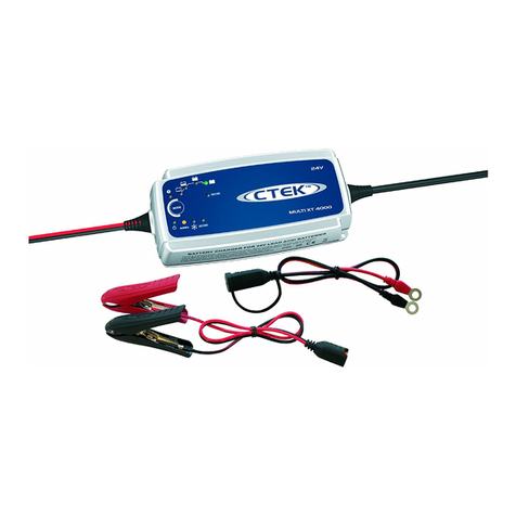
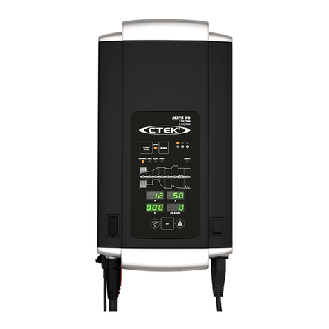
CTEK MXTS 70 User manual

EN • 3
EN
CONGRATULATIONS
to the purchase of your new professional switch mode battery charger. This
charger is included in a series of professional chargers from CTEK SWEDEN AB
and represents the latest technology in battery charging. MXTS 70 is the first
charger with multiple adjustable parameters.
QUICK GUIDE
To charge, with last used program settings
WARNING!
Batteries and electronics will be damaged if 12V batteries
are charged in 24V-setting.
Attach the cables
to the charger.
Connect the charger
to the battery
Connect
the charger
to mains supply
Press START/PAUSE-button
to start charging
Press the START/PAUSE-
button to interrupt
charging
1
2
3
4
Battery cable
Battery cable
female connector +
Temperature sensor
male connector
Battery cable
female connector -
Charger cable
male connector +/-
Mains cable
Clamps
Eyelets M8
Temperature sensor
Mains cable connector
Temperature sensor female connector
MANUAL
20015126D Manual MXTS70, All languages, Print file 003.indd 3 2011-10-11 13:01:26

4 • EN
CHARGING
For best possible charging of your batteries the voltage and current is
adjustable. In addition to that temperature compensated charging is
selectable. See below how to set the parameters for customized charging.
1. Connect the charger cables to the charger
(see connect the cables)
2. Connect the charger to the battery
(see connect the cables)
3. Connect the charger to the wall socket
The power lamp will indicate that the mains cable is connected
to the wall socket. The error lamp will indicate if the battery
clamps are incorrectly connected. The reverse polarity protection
will ensure that the battery or charger will not be damaged.
4. Press the MODE-button to select
charging program
5. Press SET-button to set parameters
6. Select voltage
•Display (h) will indicate that voltage (U) is selectable
•Display (V) will indicate set voltage
•Press +/- to change
•Press SET-button to confirm
7. Select current
•Display (h) will indicate that current (A) is selectable
•Display (A) will indicate set current
•Press +/- to change
•Press SET-button to confirm
8. Select temperature compensation
• Display (h) will indicate that temperature compensation ( ) is selectable
•Temperature sensor lamp will indicate activated temperature sensor
•Press +/- to change
•Press SET-button to confirm
9. Press the START/PAUSE-button to start
charging cycle or press MODE-button to change
charging program
10. Follow the 8-step display through
the charging process
The battery is ready to start the engine when STEP 4 is lit.
The battery is fully charged when STEP 7 is lit.
11. Stop charging at any time by pressing
the START/PAUSE-button
12. Press START/PAUSE-button
to resume charging cycle
SET
A
Ah & info
V
h
1 2 3 4 5 6 7 8
NORMAL AGM
GEL AGM
POWER
Ca/Ca SUPPLY
Amp
12V/70A
24V/35A
MXTS 70
START
PAUSE MODE
FULLY CHARGED
POWER LAMP
ERROR LAMP
TEMPERATUR SENSOR LAMP
REDUCED CURRENT LAMP
START/PAUSE-BUTTON
MODE-BUTTON
NORMAL PROGRAM
DISPLAY (V)
SET-BUTTON
DECREASE BUTTON INCREASE BUTTON
DISPLAY (h)
DISPLAY (A)
DISPLAY (Ah & info)
SUPPLY PROGRAM
Ca/Ca PROGRAM
AGM/GEL PROGRAM
AGM POWER PROGRAM
READY TO START
20015126D Manual MXTS70, All languages, Print file 003.indd 4 2011-10-11 13:01:26

EN • 5
EN
INDICATION LAMPS:
START/PAUSE LAMP
Indicates that charging has not started or has been interrupted.
Press START/PAUSE-button to start/resume.
POWER LAMP
Indicates that mains supply is connected.
ERROR LAMP
Indicates that a fault has occurred.
Se ERROR CODES for description.
Press START/PAUSE-button to clear error and interrupt charging.
TEMPERATURE SENSOR LAMP
Indicates that the temperature sensor is activated.
Voltage is automatically adjusted to optimize charge at
ambient temperature.
REDUCED CURRENT LAMP
Indicates that the maximum current is limited.
SET
A
Ah & info
V
h
1 2 3 4 5 6 7 8
NORMAL AGM
GEL AGM
POWER
Ca/Ca SUPPLY
Amp
12V/70A
24V/35A
MXTS 70
START
PAUSE MODE
INDICATION LAMPS, DISPLAYS
AND ERRORCODES
SET
A
Ah & info
V
h
1 2 3 4 5 6 7 8
NORMAL AGM
GEL AGM
POWER
Ca/Ca SUPPLY
Amp
12V/70A
24V/35A
MXTS 70
START
PAUSE MODE
SETTINGS BEFORE START:
DISPLAY (V)
Indicates voltage set
Options: 12/24 Volts
DISPLAY (A)
Indicates current set
Options: 70/50/40/30/20 A in 12V setting
Options: 35/25/20/15/10 A in 24V setting
70A/35A could only be selected for Supply program.
For Normal-, Ca/Ca-, AGM/GEL- and AGM Power-program maximum
current is 50A/25A.
DISPLAY (h)
Indicates which parameter to set
Options: U/A/
DISPLAY (Ah & info)
Displays error codes
REAL TIME INDICATION DURING CHARGING:
DISPLAY (V)
Displays output voltage
DISPLAY (A)
Displays output current
DISPLAY (h)
Alt. 1. Displays total elapsed charging time (minutes/hours)
Alt. 2. Displays time elapsed until error occured
DISPLAY (Ah & info)
Alt.1. Displays total charge delivered since start (minutes/hours)
Alt.2. Displays error codes together with ERROR lamp
ERROR CODES:
E01 REVERSE POLARITY
Connect the charger according to “CONNECT THE CABLES”
E02 OVER VOLTAGE
Battery voltage to high for the chosen charging program, check
battery voltage.
E03 TIME OUT STEP 1: DESULPHATION
Restart the charger. If charging is still being interrupted the bat-
tery is seriously sulphated and may need to be replaced.
E04 TIME OUT STEP 2: SOFT START
Restart the charger. If charging is still being interrupted the battery
can not accept charge and may need to be replaced.
E05 TIME OUT STEP 5: ANALYSE
Restart the charger. If charging is still being interrupted the bat-
tery can not keep charge and may need to be replaced.
E06 BATTERY OVERHEATED
The battery is too hot to charge. The battery is damaged and
may need to be replaced.
E07 LOW BATTERY VOLTAGE IN SUPPLY PROGRAM
Battery voltage too low or too large consumers connected. Check
if 12V battery connected in 24V battery setting or disconnect
large consumers.
E08 HIGH CURRENT IN SUPPLY PROGRAM
Check if clamps are short circuited or connected reversed polarity.
E99 OVER VOLTAGE PROTECTION
If battery voltage is below 17V the ERROR lamp is lit when 24V
setting has been selected.
Alt 1. Press START/PAUSE button to charge with 12V setting.
To set the parameters for customized charging proceed with
“CHARGING” step 5 to 8
Alt 2. Press INCREASE or DECREASE button to change to
24V setting. Press START/PAUSE button to resume. To set the
parameters for customized charging proceed with “CHARGING”
step 5 to 8.
SET
A
Ah & info
V
h
1 2 3 4 5 6 7 8
NORMAL AGM
GEL AGM
POWER
Ca/Ca SUPPLY
Amp
12V/70A
24V/35A
MXTS 70
START
PAUSE MODE
SET
A
Ah & info
V
h
1 2 3 4 5 6 7 8
NORMAL AGM
GEL AGM
POWER
Ca/Ca SUPPLY
Amp
12V/70A
24V/35A
MXTS 70
START
PAUSE MODE
10-7012/24
E01-E99
E01
SET
A
Ah & info
V
h
1 2 3 4 5 6 7 8
NORMAL AGM
GEL AGM
POWER
Ca/Ca SUPPLY
Amp
12V/70A
24V/35A
MXTS 70
START
PAUSE MODE
SET
A
Ah & info
V
h
1 2 3 4 5 6 7 8
NORMAL AGM
GEL AGM
POWER
Ca/Ca SUPPLY
Amp
12V/70A
24V/35A
MXTS 70
START
PAUSE MODE
SET
A
Ah & info
V
h
1 2 3 4 5 6 7 8
NORMAL AGM
GEL AGM
POWER
Ca/Ca SUPPLY
Amp
12V/70A
24V/35A
MXTS 70
START
PAUSE MODE
SET
A
Ah & info
V
h
1 2 3 4 5 6 7 8
NORMAL AGM
GEL AGM
POWER
Ca/Ca SUPPLY
Amp
12V/70A
24V/35A
MXTS 70
START
PAUSE MODE
20015126D Manual MXTS70, All languages, Print file 003.indd 5 2011-10-11 13:01:28

6 • EN
5
34
CHARGING PROGRAMS
Choose program by pressing the MODE-button.
Adjust parameters according to "CHARGING" (6–8).
Press START/PAUSE button to start the selected program.
The table explains the different Charging Programs:
Program Battery Size
(Ah) Explanation Temp range
NORMAL 40–150 0A h
20–750Ah Use for WET and MF batteries. -20°C–+50°C
(-4ºF–+122ºF)
Ca/Ca 40–1500A h
20–750Ah
Use for Ca/Ca batteries. Use Ca/Ca-program to maximize charge with
minimum loss of fluid. Including RECOND step. Recond your battery once
per year and after deep discharge to maximise lifetime and capacity.
-20°C–+50°C
(-4ºF–+122ºF)
AGM/GEL 40–1500Ah
20–750Ah For AGM and GEL batteries which are recommended to receive lower
voltage charge. -20°C–+50°C
(-4ºF–+122ºF)
AGM POWER 40–1500A h
20–750Ah Use for AGM batteries which are recommended to receive higher voltage
charge. -20°C–+50°C
(-4ºF–+122ºF)
SUPPLY 40–1500A h
20–750Ah
Use as 12V/24V power supply or use for float maintenance charging when
100% capacity of the battery is required. Supply program activates step 7
without time or voltage limitation. Supply program enables the charger to
deliver 70A/12V or 35A/24V for 30 seconds.
-20°C–+50°C
(-4ºF–+122ºF)
CONNECT THE CABLES
If the battery clamps are incorrectly connected, the reverse polarity protec-
tion will ensure that the battery and charger are not damaged.
1. Connect the battery cable, including the temperature sensor, to the
charger
2. Connect the mains cable to the charger
3. Connect the red clamp to the battery´s positive pole.
4. Connect the black clamp to the vehicle chassis remote from the fuel pipe
and the battery.
5. Connect the charger to the wall socket
6. Disconnect the charger from the wall socket before disconnecting the
battery
7. Disconnect the black clamp before the red clamp
WARNING!
Risk for short circuiting the battery cables. Connect charger cables
to the charger before connecting the battery
WARNING!
Risk for electrical shock if touching positive and negative terminals
when charging
1
–
+–
+
2
12V 24V
Current Battery size Min Battery size Max Current Battery size Min Battery size Max
20A 40Ah 100Ah 10A 20Ah 50Ah
30A 60Ah 150Ah 15A 30Ah 75Ah
40A 80Ah 200Ah 20A 40Ah 100Ah
50A 100Ah - 25A 50Ah -
70A* 100Ah - 35A* 50Ah -
• Using higher current than recommended may result in batteries not being
completely charged.
•Using lower current than recommended will prolong the charging time.
• The currents are the maximum recommended current for battery charg-
ing. If a parallel consumer is connected then the current setting could be
increased with this current value.
• Some battery manufacturer could recommend different values. Please
check with the manufacturer if uncertain. The main recommendations are
that Gel batteries should be charged in the lower current range, Power
AGM’s in the upper range and most other battery types in the mid-range.
*) 70/35A Could only be selected for Supply program
Some vehicles may
have positively
earthed batteries
3. Connect the black
clamp to the battery´s
negative pole.
4. Connect the red clamp
to the vehicle chassis
remote from the fuel
pipe and the battery.
7. Disconnect the red
clamp before the black
clamp.
20015126D Manual MXTS70, All languages, Print file 003.indd 6 2011-10-11 13:01:30

EN • 7
EN
1
ANALYSE RECOND PULSE
DESULPHATION SOFT START BULK ABSORPTION
15.8V
31.6V
Increasing voltage to:
14.7V
29.4V
50A
25A
50A until 12.6V
25A until 25,2V
Increasing voltage to:
14.4V
28.8V
50A
25A
17
15.8V
31.6V
15.8V
31.6V
15.8V
31.6V
50A until 12.6V
25A until 25,2V
50A until 12.6V
25A until 25,2V
50A until 12.6V
25A until 25,2V
Increasing voltage to:
14.4V
28.8V
50A
25A
Increasing voltage to:
14.9V
29.8V
50A
25A
14.4V
28.8V
Declining current
14.7V
29.4V
Declining current
14.4V
28.8V
Declining current
14.9V
29.8V
Declining current
Checks if voltage
drops to:
12V
24V
Checks if voltage
drops to:
12V
24V
Checks if voltage
drops to:
12V
24V
Checks if voltage
drops to:
12V
24V
Max 15.8V
Max 31.6V
1.5A
13.6V
27.2V
Max 50A
Max 25A
13.6V
27.2V
Max 50A
Max 25A
13.6V
27.2V
Max 50A
Max 25A
13.6V/Max 70A
27.2V/Max 35A*
12.7V‒14.4V
25.4-28.8V
50‒5A
25-2,5A
12.7V‒14.7V
25.4-29.4V
50‒5A
25-2,5A
12.7V‒14.4V
25.4-28.8V
50‒5A
25-2,5A
12.7V‒14.9V
25.4-29.8V
50‒5A
25-2,5A
Limit: Max 30h Max 10h 3 minutes 30 min or 4h
depending on
battery voltage
10 days
Charge cycle restarts
if voltage drops
Charge cycle restarts
if voltage drops
Max 4h Max 4h
2 3 4 5
FLOAT
6 8
NORMAL
Ca/Ca
AGM/GEL
AGM POWER
SUPPLY
VOLTAGE (V)
CURRENT (A)
13.6V
27.2V
Max 50A
Max 25A
MOUNTING
When permanently mounting the charger, mount the charger on a firm
surface. Fix the charger with screws in the four holes. Use screws intended for
the surface. Allow space around the charger to not interfere with air cooling.
CHARGING PROGRAMS
*) SUPPLY program is not time or voltage limited
STEP 1 DESULPHATION
Detects sulphated batteries. Pulsing current and voltage, removes sulfates from
the lead plates of the battery restoring the battery capacity.
STEP 2 SOFT START
Tests if the battery can accept charge. This step prevents charging a defect
battery.
STEP 3 BULK
Charging with maximum current until approximately 80% battery capacity.
STEP 4 ABSORPTION
Charging with declining current to maximize up to 100% battery capacity.
STEP 5 ANALYSE
Tests if the battery can hold charge. Batteries that can not hold charge may
need to be replaced.
STEP 6 RECOND
Choose the Ca/Ca program to add the Recond step to the charging process.
During the Recond step voltage increases to create controlled gasing in the
battery. Gasing mixes the battery acid and gives back energy to the battery.
STEP 7 FLOAT
Maintaining the battery voltage at maximum level by providing a constant
voltage charge.
STEP 8 PULSE
Maintaining the battery at 95–100% capacity. The charger monitors the battery
voltage and gives a pulse when necessary to keep the battery fully charged.
READY TO USE
The table shows the estimated time for empty battery to 80% charge
BATTERY SIZE
20Ah 50Ah 100Ah 200Ah 500Ah
CHARGING
CURRENT
10A 2h 5h
20A 2h 5h
25A 2h 4h 8h 20h
50A 2h 4h 10h
20015126D Manual MXTS70, All languages, Print file 003.indd 7 2011-10-11 13:01:31
Other manuals for MXTS 70
1
Table of contents
Other CTEK Batteries Charger manuals

CTEK
CTEK MXS 3.6 User manual

CTEK
CTEK MULTI XS 25000 User manual

CTEK
CTEK 1082 User manual

CTEK
CTEK MXS 7.0 User manual

CTEK
CTEK MXS 8.0 User manual

CTEK
CTEK D250S Dual User manual

CTEK
CTEK XS 800 User manual

CTEK
CTEK NJORD GO User manual

CTEK
CTEK MULTI US 25000 User manual

CTEK
CTEK MUS 4.3 TEST&CHARGE User manual