Selectronic SP PRO 2i Series User manual
Installation • Operation • Service
Instruction Manual for
SP PRO series 2i
Interactive Inverter Charger

Selectronic Australia Pty Ltd
© 2020
Ph +61 3 9727 6600
Fax +61 3 9727 6601
www.selectronic.com.au

Thank you for purchasing a Selectronic SP PRO series 2i sine wave Interactive Inverter Charger
optimised for either grid connected power systems (also called Solar Hybrid Power Systems) or
O Grid systems (no grid power available).
Selectronic has an accredited Quality Assurance system covering both their manufacturing and
design operations with over 25 years experience designing power conversion equipment for both
domestic and industrial purposes.
As a result Selectronic has had many opportunities to listen to both integrators and system
owners to determine their real needs.
We have learnt from our customers that:
• Modern solar energy systems need to do more than provide power when the sun shines,
• A simple or complex system should be a matter of choice. The inverter should be able to
perform with ease of conguration yet be capable of integrating into the most advanced
energy system.
• Battery longevity is paramount. A combination of battery protection and the best charging
methods are essential.
• Monitoring / conguration software should be user friendly with intuitive “at a glance”
menu clarity.
The SP PRO has been designed with these, and many other criteria in mind.
In addition to power conversion the SP PRO controls the operation of the entire energy system
ensuring all sources of renewable energy are fully utilised whilst reducing the use of either grid
power or generator power. The SP PRO is a complete Energy System.
With the easy to use SP LINK Site Conguration Wizard the SP PRO can easily be “hung on
the wall” and congured to suit most renewable energy installations. Further functionality is also
possible when using the Advanced Conguration settings to tailor the SP PRO to suit a more
complex system requirements.
We are always interested in feedback about this document or the SP PRO. Please do not
hesitate to contact us via our web site
www.selectronic.com.au
.
When installed and maintained correctly the SP PRO will give many years of trouble free
operation.
INTRODUCTION

Contents
4 | Doc #OI0003 Part #004122 Rev29 2020
INTRODUCTION
Australian/New Zealand Warranty 6
Using This Manual 6
Included in this package 7
Glossary of Terms 7
Conguring the SP PRO using SP LINK 7
Product Overview 8
Solar Hybrid Support and Grid Feed Systems 8
O Grid Stand Alone Power Systems (SPS) 9
Precautions and Safety 10
Who should install this unit 10
Protective Earth connection 10
Multiple Hazardous Energy Sources 10
Preparation 11
Installation 11
Maintenance 11
Inverter may start automatically 11
Backup Generator may start automatically 11
Battery 11
INSTALLATION
Installation-General Requirements 12
Environmental Considerations 13
Eects of altitude on the SP PRO 13
Preparation 14
Installation of SPMC models 15
Installation of SPLC models 18
Battery Cabling Requirements 21
Battery Fusing / Circuit Breakers 21
DC Wiring SPMC Models 22
DC Terminal Torque settings - SPMC and SPLC 22
DC Wiring SPLC Models 22
Expansion Card Warning - 120VDC model 23
Current Shunt Wiring 23
Battery Temperature Sensor 23
Battery Wiring (DC) Preparation 24
AC Wiring 25
Earth Wiring 25
Residual Current Device (RCD) Type
Recommendation 26
AC Wiring Preparation 26
Backup Generator (Advanced Feature) Control
Wiring 27
Serial Port Connection 27
Gland Plate Fit out 27
Initial Start up Procedure 27
Labelling 27
Installation-System Configuration 28
Powerchain 28
Managed Battery Preparation 28
Managed AC Coupled Preparation 29
Generic AC Coupled Preparation 31
Powerchain - Three Phase Preparation 32
Powerchain - Split Phase Preparation 32
DC Coupled Charge Controller Preparation 33
Installation-Ancillary Components 34
Inputs and Output 34
External AC Source contactor 37
Adding a backup Generator (Solar Hybrid only) 38
Adding a Generator (O Grid only) 39
Installation-Communications 40
Communications Overview 40
Communications Port Functions 41
Select.live Remote Monitoring 42
SP PRO Ethernet Adaptor 43
Installation-Configure with SP LINK 44
Overview 44
Conguring The SP PRO For All System
Congurations 45
Contents

Contents
Doc #OI0003 Part #004122 Rev29 2020 | 5
Installation-Commissioning 46
Introduction 46
Diagnostics during Commissioning 46
Common System Checks 47
Powerchain Systems 48
External AC Source Contactor 49
Continue Common System Checks 50
Checking Managed AC Coupled Systems 51
Checking Generic AC Coupled 52
Checking DC coupled 52
External Generator 53
OPERATION
Controls and Indicators 54
User Interface 54
SP PRO Operation 56
Battery Management 57
Battery State of Charge (SoC) monitoring and
control 57
Battery Voltage monitoring and control 57
Battery Charging Operation 58
Battery Charging Cycle 59
Battery Temperature Compensation 60
Renewable Management 60
Generator Controls for O Grid 61
Backup Generator Controls (with option) 61
Inverter External Alarm 61
SERVICE
Service and Maintenance 62
Multiple Sources of Supply 62
Cleaning the Fan and Fan Filter 62
Monitoring the operation of the SP PRO 62
System Shutdown and Startup 63
Installer Maintenance of SP PRO 63
System Maintenance 63
Battery Maintenance and replacement 63
Troubleshooting 64
Front Panel Indicators 64
Troubleshooting with SP LINK 66
AC Power Problems 67
Battery Problems 67
Grid related Problems 67
O Grid Generator Start/Stop Problems 68
Inverter Startup Problems 69
Resetting inverter with or without Restoring
Factory Default settings 69
Appendix A - Specifications 70
Standards Compliance 70
Product Specications 70

INTRODUCTION | Warranty and manual use
6 | Doc #OI0003 Part #004122 Rev29 2020
Australian/New Zealand Warranty
The Selectronic SP PRO product is warranted by the manufacturer to the original purchaser only. The
manufacturer will bear the cost of parts and labour to repair any faults found within the terms and period of
this warranty. For full warranty terms and conditions please see the warranty card packed with the SP PRO
inverter.
If you have purchased the SP PRO outside Australia or New Zealand, please see the separate warranty
supplied by the authorised distributor in your country.
Warranty registration is carried out online at.www.selectronic.com.au
Selectronic Australia shall be under no obligation to warrant any equipment which has been improperly
installed, stored, or handled, or which has not been operated or maintained according to this manual, nor for
any operating mistakes and consequences arising from them.
Using This Manual
While every attempt has been made to ensure this manual is as self explanatory and clear as possible, there
are some technical issues and safety warnings that require thorough understanding. It is extremely important
that the owner and integrator/installer follow all of the instructions set out in this document; failure to do so
may void the warranty and not give the full benets that this product can provide.
This manual is divided into four sections to allow fast access to relevant information. The heading on each
page indicates the section.
INTRODUCTION This section, which provides a brief overview of the SP PRO including information
about warranties and terms used in this manual.
INSTALLATION Contains information relevant to the installers from unpacking the unit to conguring
the settings of the SP PRO using SP LINK interface software. Also see the SP LINK
manual (contained in the SP LINK software) for Conguration Settings and Monitoring
details
OPERATION Information relevant to the user and covers the day to day operation of the SP PRO as
well as certain safety warnings. This section presumes the unit’s installation and set up
is complete and correct.
SERVICE Provides information to service personnel in regards to preventative maintenance and
troubleshooting in case of a fault.
A PDF copy of this manual may be downloaded from the Selectronic web site www.selectronic.com.au and is
also included within the Help menu of the SP LINK software.
Throughout the manual the following symbols will be repeated. These symbols are very important.
This symbol indicates danger. Failure to observe this warning may result in serious injury or
death, loss of property or damage to the power system
This symbol is used to draw attention to information that will assist in making full use of the
system or gives notice to information which may not seem immediately apparent

INTRODUCTION | This Package and SP LINK
Doc #OI0003 Part #004122 Rev29 2020 | 7
Included in this package
• Mounting bracket
• Rear Outlet Mesh Cover (SPLC models only)
• Contents checklist, checked and signed by Selectronic
• Know Your SP PRO display quick reference card
• Warranty card.
• Tool kit - (Hex Drive bits - T10 Torx, T20 Torx, T25 Torx, 5 mm Hex, 6 mm Hex, long extension)
• USB Cable - Type B
SP LINK software: Download the latest version from the Selectronic web site www.selectronic.com.au
Glossary of Terms
Powerchain A method for allowing the integration of up to four SP PROs in a single phase power
system or four SP PROs per phase in a multi phase power system.
DC Coupled system The Solar is connected to the DC side of the inverter system through a Solar Controller.
AC Coupled system The Solar is connected to AC Side of the inverter system via a separate Grid Tie inverter.
Solar Hybrid A battery based power system that is connected to the electricity grid
O Grid A battery based power system that is remote from the electricity grid
AC Source The primary AC input connected to the SP PRO, e.g., Mains Grid or Backup Generator.
Site File An SP LINK le that is set up for each SP PRO inverter to be connect to.
Conguration File A le that contains all the settings to be loaded into the SP PRO. This is normally linked
to a site le.
Solar Array A collection of Solar Panels.
PV Photo Voltaic solar power
Sealed Battery A lead acid battery with no access to the electrolyte - either valve regulated or gel.
Flooded Battery A lead acid battery with access caps for maintaining the electrolyte - replacing water lost
during recharge operations. Hydrogen gas discharged during normal recharge
Lithium Battery A battery based around lithium technology. For example, Lithium Iron Phosphate
(LiFePO4)
Managed Battery Where the Battery Management System (BMS) communicates with the SP PRO.
BMS Battery Management System. An electronic battery monitoring system that keeps the
battery bank within its safe operating conditions whilst maximizing battery health.
State of Charge (SoC) The amount of charge in the battery bank, expressed as a percentage of the
battery capacity. When SoC is 100%, the battery is fully charged.
Battery Sense Three terminals located in the SP PRO for a direct connection to the battery terminals
and battery mid-point. Used to provide battery sense measurements and a pre-charge
function that reduces inrush current during DC power up .
Conguring the SP PRO using SP LINK
Provided as a free download, the SP LINK software is a convenient conguration and monitoring tool used
for integrating the SP PRO into the energy system. The SP PRO inverter must be congured using SP LINK
before it will produce any output power.
SP LINK also accesses the monitoring and logging features of the SP PRO to allow the user and installer to
monitor system performance and to assist in the diagnoses of any system issue.
A PC running SP LINK is simply connected to the SP PRO via a USB port to open up the full potential of the
SP PRO Energy System.

INTRODUCTION | Product Overview
8 | Doc #OI0003 Part #004122 Rev29 2020
The SP PRO Sine wave Interactive Inverter Charger is designed specically for either Solar Hybrid (grid
support / grid feed) or O Grid (no grid available) operation.
With Powerchain capability, the SP PRO can be congured as either a single phase power system with up to
four SP PROs or a three phase conguration with up to twelve SP PROs (four per phase). A Split phase with
eight SP PROs is also possible. With all SP PROs in a Powerchain system operating in perfect harmony, the
power system is congured, controlled and monitored as one.
As a battery based inverter, charger and system controller all in the one product. Each SP PRO has a
congurable export power limit suitable for many export limited Solar Hybrid applications.
With its in built generator controller the SP PRO is also the ideal choice for all O Grid installations or Solar
Hybrid systems with generator back up.
The SP PRO is compatible with virtually any DC renewable charging source (such as a DC solar controller).
Also any AC renewable source (such as a grid tie inverter) is compatible with the SP PRO in a Solar Hybrid
system without limited export power.
For O Grid Systems or Solar Hybrid systems requiring export limiting the Selectronic Managed AC Coupling
must be used. Its advanced features include the precise control of either a Selectronic Certied (SCERT) grid
tie inverter or the Selectronic SelectSun grid tie inverter, making it ideal for either an O Grid charging system
or maintain a Solar Hybrid export limit.
Solar Hybrid Support and Grid Feed Systems
Product Overview
Chapter One
INTRODUCTION | Product Overview
Doc #OI0003 Part #004122 Rev29 2020 | 9
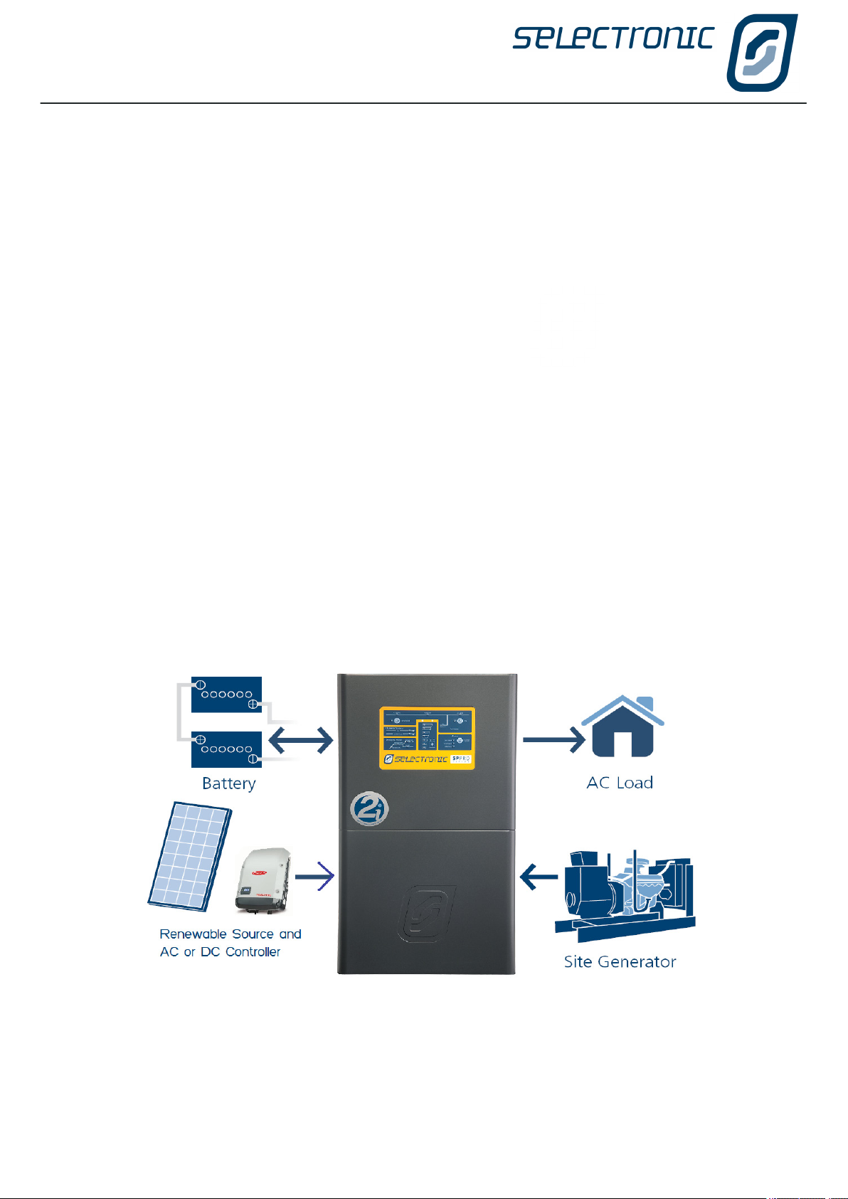
In Solar Hybrid, the renewable energy can be directed to power the AC load, recharge the battery bank and/
or export to the grid. The direction and priority of the energy ow can be varied depending on the time of day,
battery SoC or load demands allowing the maximum use of the renewable energy (such as PV solar) and
stored battery energy to supply loads to take advantage of variable electricity taris. A Solar Hybrid system
will allow the user to only use grid electricity when they choose.
By using the optional “Grid fail - Gen backup” module the SP PRO can be congured to automatically start
and stop a generator during a prolonged power outage. When the generator is running, the SP PRO will use
the generator to power the site load plus use any additional generator capacity to charge the batteries.
O Grid Stand Alone Power Systems (SPS)
The SP PRO is the heart of the power system. It quietly provides AC power from the battery bank and
renewable sources. By using SP LINK the SP PRO can be congured to monitor battery state of charge
and load conditions to automatically start and stop the generator as required to charge the batteries and
supply loads heavier than the SP PRO can eciently handle. These features, when correctly congured, will
increase the battery life and reduce generator running costs.
When the generator is running, the SP PRO will use the generator to power the site load; plus use any
additional generator capacity to charge the batteries. When the site loads are greater than the generators
output, the SP PRO will add its power to the generator. When the site loads are reduced, the SP PRO will
return to battery charging. The above operation happens automatically, whilst always maintaining “no break”
power to the site.
An SP PRO managed AC Coupled system is suitable for O Grid systems due to the superior battery
charging functions that are achieved by a sophisticated system control and monitoring communications link
between the SP PRO and compatible grid inverters.
INSTALLATION | Precautions and Safety
10 | Doc #OI0003 Part #004122 Rev29 2020
Warning: If this equipment is used in a manner not specied by the manufacturer as contained
in this manual and other operational documents and Instructions, then the protection provided
by the equipment may be compromised.
Who should install this unit
The SP PRO is designed for easy installation and can be installed by any suitably qualied person.
The voltages produced within a power system are hazardous. Even though the SP PRO may derive its input
from a battery, the extremely high current capability of a battery bank is hazardous. Additionally the high
voltage battery banks (120V) used in the SPMC1201, SPLC1200 and SPLC1202 are hazardous and the
output and input AC voltage in all the SP PRO models is just a hazardous as grid electricity.
All AC connections and hazardous DC connections to the SP PRO must be carried out by a qualied
Electrical contractor or similar, failure to do so will contravene legal requirements.
All DC wiring must be carried out by a person experienced with DC electrical circuits and must understand
high current low voltage circuits. To ensure an ecient system installation, cable sizing and voltage drop
must be understood and the recommendations within this manual followed.
Selectronic Australia shall have no obligation as to any equipment which has been improperly installed,
stored, or handled, or which has not been operated or maintained according to this manual, nor for any
operating mistakes and consequences arising from them.
This product is not to be used for Life Support equipment
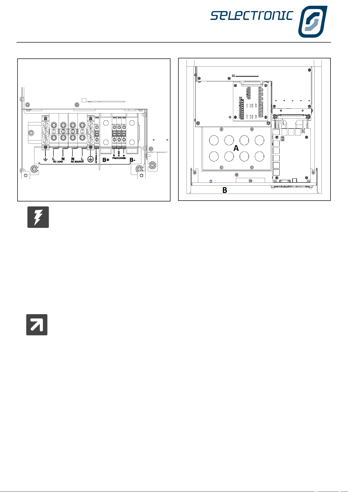
Protective Earth connection
It is critical that all protective earth connections made within the SP PRO use the
protective earth terminal. This is the earth terminal that is on the right hand side of
the AC terminals and marked with a earth symbol enclosed in a circle.
Multiple Hazardous Energy Sources
Hazardous voltages and energy are generated by the SP PRO, are fed into the
SP PRO by external wiring from multiple sources and are stored in capacitors after
the SP PRO is switched o and disconnected from external wiring.
Precautions and Safety
Chapter Two

INSTALLATION | Precautions and Safety
Doc #OI0003 Part #004122 Rev29 2020 | 11
Preparation
Whilst every eort has been made to pack the SP PRO in a way that will provide adequate protection,
damage in transit can occur. Please carefully check the packaging and the SP PRO for signs of damage and
for all components mentioned in the “Included in the Package” section of this manual.
Please report any damage or missing parts to Selectronic or a Selectronic Authorised Distributor.
Please retain the original packaging for the safest and most eective method of repackaging if required.
Installation
The SP PRO requires adequate ventilation, away from hot equipment. Do not obstruct the airow
passage of the SP PRO case (top and bottom). Ensure when installed in an enclosed space that
there is adequate ventilation.
The SP PRO must be located in a place away from electrolyte and corrosive aerosols.
The SP PRO contains arcing contacts so must not be located near explosive gas mixtures such
as hydrogen from batteries or diesel fumes.
Maintenance
Ensure that all energy sources are isolated before working on connected wiring. A backup
generator may start or power may be restored by the SP PRO at any time. Never work on
equipment or investigate a problem without following appropriate safety isolation procedures.
Inverter may start automatically
The SP PRO automatically starts and/or restarts and may restore power at any time. If a fault
or overload is detected the SP PRO will shutdown and may automatically attempt to restart at
varying intervals of up to several hours.
Backup Generator may start automatically
The SP PRO automatically starts and/or restarts a backup generator (when a Grid Fail - Gen
Backup option is installed). If a fault or overload caused the SP PRO to shutdown then it will
automatically attempt to start and restart the backup generator.
Battery
Batteries are very dangerous. Please read the safety information provided by the battery
supplier.
• Battery acid is dangerous.
• Batteries can emit hydrogen gas, which is explosive.
• Batteries connected in series can produce hazardous voltages.
• Batteries are capable of sourcing extremely high output currents. Short circuit or high overload currents
can be extremely hazardous and cause high current arcs, burns and explosions.
• Disconnecting a DC power connection (even on one battery cell) can cause dangerous high-energy DC
arcs, which can cause serious burns and eject hot particles, and can be dicult to extinguish.
• Disconnecting a DC power connection (even on one battery cell) can cause renewable sources to
produce large voltages (much larger than the battery voltage) on battery terminals and DC wiring. Such
voltages can be lethal. They can also damage the SP PRO. Only suitably trained and qualied personnel
should disconnect any DC power connection, including battery cell connections, and only with suitable
procedures and safety precautions.
• System battery voltages of 60 V or greater are to be treated as a hazardous voltage.

INSTALLATION | General Requirements
12 | Doc #OI0003 Part #004122 Rev29 2020
Installation-General Requirements
Chapter Three
The SP PRO must only be installed by suitably qualied personnel.
Many procedures covered in the INSTALLATION sections of this manual have
inherent risks. Whilst the SP PRO is designed to be safe, including safety
features never before found in an inverter (such as Earth / Neutral bond
monitoring), the voltages connected to or generated within the SP PRO are
hazardous and potentially fatal.
It is the responsibility of the installer to ensure the installation and all the
wiring is carried out according to all safety standards that are applicable to the
installation. The wiring diagrams and installation instructions are given as a
guide only and compliance to appropriate standards is the responsibility of the
installer.
The following section provides general installation instructions for the SP PRO . For information
on specic congurations please refer to the “Installation-Specic Applications” Section in this
manual and the relevant installation guide supplied with any required installation options.
All installation notes including this manual can be downloaded from the Selectronic web site at:
www.selectronic.com.au
INSTALLATION

INSTALLATION | General Requirements
Doc #OI0003 Part #004122 Rev29 2020 | 13
Environmental Considerations
ENVIRONMENTAL CATEGORY
The SP PRO is design with an Environmental Category (as dened by IEC 62109.1) for “Indoor,
unconditioned. The SP PRO must be protected by a building or enclosure from direct rain, sun, wind-blown
dust, fungus and radiation to the night sky.
The SP PRO must be installed in a dry environment.
POLLUTION DEGREE 2
The SP PRO is designed to operate in a Pollution Degree 2 environment. Normally only non-conductive
pollution occurs with occasional temporary conduction due to condensation expected.
TEMPERATURE
The SP PRO is designed for an ambient operating temperature between -20°C and 60°C, with a storage
temperature range between –20°C and 70°C.
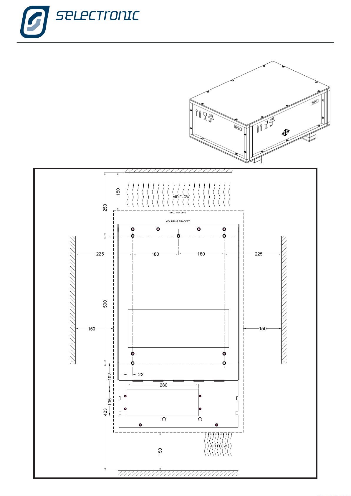
AIR FLOW
For best performance ensure nothing impedes ambient air from being drawn in the bottom of the unit and
that hot exit air is vented away and doesn’t recirculate into the unit. Particular attention must be paid when
installed inside a cabinet or enclosure.
CLEARANCE FROM OTHER EQUIPMENT
A recommended clearance distance of 150 mm around all sides, top and bottom. Particular care must be
taken when mounting near other heat producing equipment.
HUMIDITY TOLERANCE
The SP PRO is designed to operate in a humidity range of 0 – 99% non condensing.
INGRESS OF PARTICLES
The SP PRO has been designed to meet IP rating 43 (Protected against solid objects larger than 1.0 mm /
protected against water falling as a spray at up to 60 degrees from the vertical).
Eects of altitude on the SP PRO
Altitude
(m)
Derating Factor
@ 40°C
0, sea level 1.00
1000 0.95
1500 0.90
2000 0.85
The power rating of the SP PRO should be compensated for the eects of altitude by applying the
appropriate derating factor. For example, at 2000 m above sea level, 6 kW x 0.85 = 5.1 kW. The altitude
compensated rating is still at 40°C.

INSTALLATION | General Requirements
14 | Doc #OI0003 Part #004122 Rev29 2020
Preparation
The selection of a suitable site and good preparation is essential in gaining optimum performance from the
SP PRO.
SP PRO Inverter performance is dependent upon the environmental operating conditions, in particular ambient
temperature and ventilation. In addition safety aspects must be considered, such as:
• Restrict access to authorised personnel only.
• Consideration of maintenance of ambient temperatures to ensure performance within product
specication.
• Positioned away from heat producing devices such as generators.
• Adequate ventilation, adhering to the minimum clearances required for adequate heat dissipation.
Minimum 150 mm clearance from top, bottom and sides.
• In a covered location away from direct rain. The SP PRO has an environmental rating of IP43 which
makes it unsuitable for water spray that is greater than 60 deg from the vertical or greater than 0.7 litres
per minute.
• In a location shaded from direct sunlight.
• Away from any explosive gas.
• Rodent proof.
• In a clean environment away from dust, iron lings, workshop pollutants and other small particles.
• Enough room to remove the cover.
• The provision of infrastructure for monitoring - example data cables
The SP PRO should be installed in a separate area to the battery system (where used). The battery bank
can emit explosive gas (hydrogen) and this must be vented outside and away from the SP PRO. The battery
system should not be accessible by the user.
When batteries are used in the system it is recommended that the installation be in lockable area with a separating
partition or enclosure for the battery bank.

INSTALLATION | Installation of SPMC models
Doc #OI0003 Part #004122 Rev29 2020 | 15
1 - Unpack the SP PRO onto a at surface. When
removing the SP PRO from its packaging carefully inspect
for any damage that may have occurred in transit. Damage
must be reported to the supplier immediately.
Installation of SPMC models
INSTALLATION | Installation of SPMC models
16 | Doc #OI0003 Part #004122 Rev29 2020
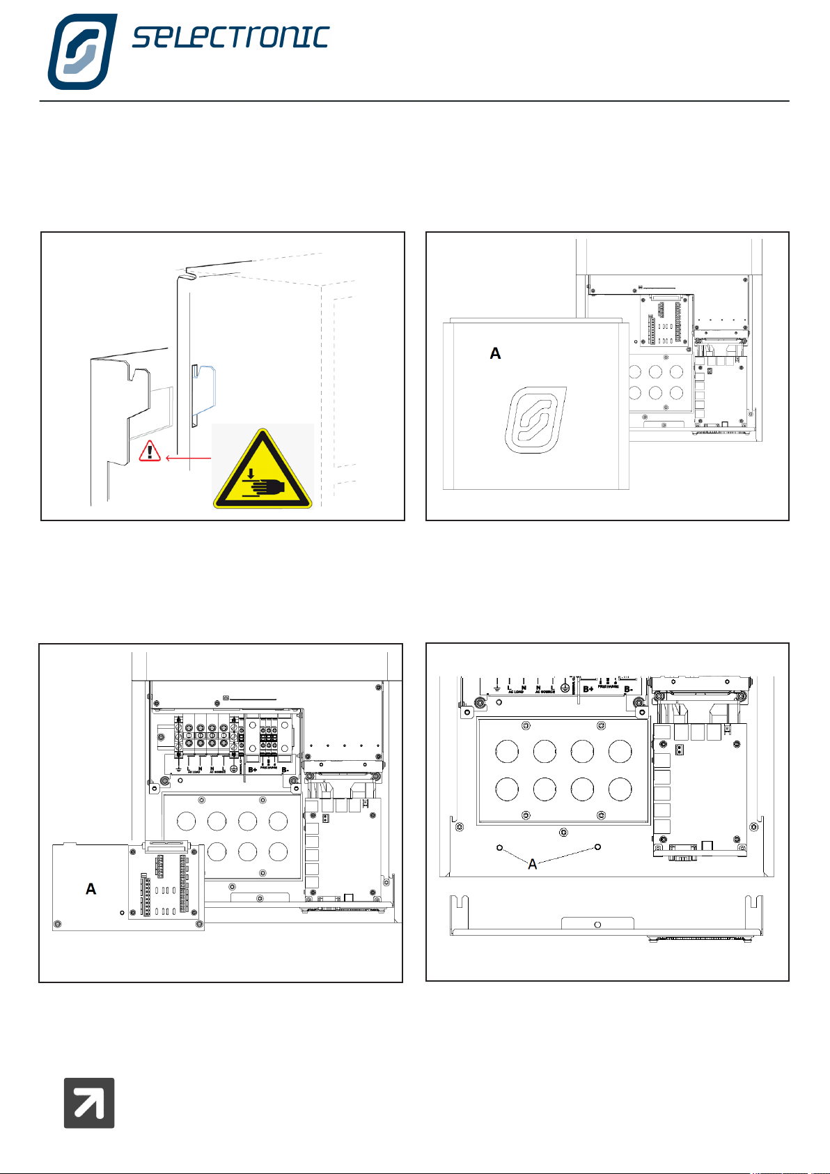
3 - Leave access cover (A) in place. Lift inverter from
underneath whilst stabilising top. Inverter is top heavy
and gloves must be worn. Mount the SP PRO on the
mounting plate by rst hooking the top of the inverter over
the projections and lowering it into position. Care should be
taken to observe Pinch Point warning.
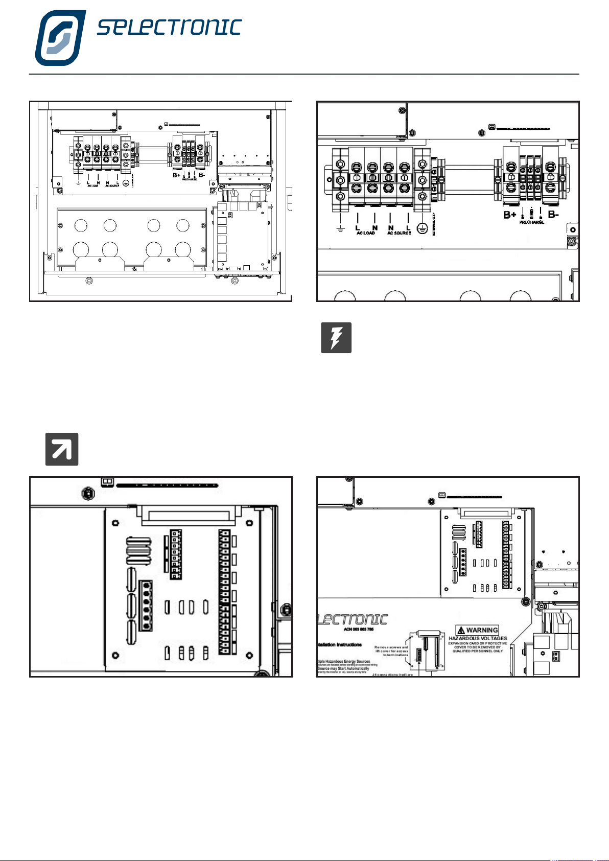
4 - With a T25 torx driver, remove the access cover(A)
by unscrewing the two M5 Torx screws at the bottom of
the SP PRO.
5 - Using the T20 torx driver remove the terminal cover
and expansion card(A) by undoing the 2 screws.
6 - The lower gland plate can be removed if required to
give greater access to wiring terminals using T25 torx
driver. NB, side screws need only be loosened.
Secure the bottom of the SP PRO to the mounting plate with
two M5 Torx screws. (A on above diagram)
7 - STOP: Detailed instruction for wiring SP PRO contained on the following pages. These
MUST be followed before proceeding with installation.
2 - Diagram previous page. Choose a suitable weight bearing and temperature resistant surface to mount the SP PRO.
Mounting MUST be to solid timber studs, solid timber, brick, masonry or other load bearing wall. DO NOT mount directly
to plaster. Max temperature is ambient +30 degrees C, max weight is 45 kg. The display of the SP PRO should be at eye
level. There should be no obstructions to the clear passage of air. Use the 6 x M8 holes to mount the bracket.
.
NOTE: Any wiring via the rear gland plate (attached to mounting bracket) can be rued in before mounting the SP PRO.
INSTALLATION | Installation of SPMC models
Doc #OI0003 Part #004122 Rev29 2020 | 17
8- Wiring must only be carried out by
suitably qualied installers and must
adhere to all relevant standards.
9 When all the AC wiring is complete reinstall the
terminal cover and expansion card.
Important points
• Failure to ll any holes in rear gland plate (A) or lower
gland plate (B) will reduce IP rating and compromise
thermal design.
• Installation of the included battery temperature sensor
in non-managed battery systems is imperative for their
correct and accurate charging. Where a managed battery
is installed the SP PRO reads the battery temperature
from the battery’s BMS therefore the temperature sensor
is not required.
Note: The rear gland plate (A) is screwed to the mounting bracket. This allows all wiring to
be carried out after the mounting bracket is installed and before the SP PRO is hung on the
mounting bracket.
INSTALLATION | Installation of SPLC models
18 | Doc #OI0003 Part #004122 Rev29 2020
Installation of SPLC models
1 - Undo ten bolts (7/16“) to remove lid on packing
crate. Cardboard tray contains mounting plate, rear
air outlet mesh cover and all documentation.
Inspect for damage in transit and report any to the
supplier immediately.

INSTALLATION | Installation of SPLC models
Doc #OI0003 Part #004122 Rev29 2020 | 19
5 - Mount the SP PRO on the mounting plate by rst
hooking the top of the inverter over the projections
on the mounting plate and lowering it into position.
Care should be taken to observe Pinch Point warning.
Secure the bottom of the inverter to the mounting plate
with two M6 bolts provided.
6 - Using T25 Torx driver remove the cover by
unscrewing two screws at the bottom of the
SP PRO.
4 - Undo 10 bolts (7/16“) to remove sides from
the packing base. Undo 8 bolts (7/16“) to remove
clamps from handles. DO NOT remove front
access cover.
HEAVY: Take care when lifting - 105 kg
SHARP: Use gloves - handle edges sharp.
TOP HEAVY: Secure unit when standing
unit upright.
Stand unit upright using handles.
REAR AIR OUTLET MESH COVER: Fit and secure
with six thumb screws
2 - Cable entry is either from below or wall entry.
Gland plates are inter changeable . Gland plates
secure to the underside of unit base or to the inside
of the mounting plate using four T25 Torx screws.
NOTE: Any wiring via the rear gland plate (attached to
mounting bracket) can be rued in before mounting the
SP PRO.
3 - See Diagram on previous page
Choose a suitable weight bearing and temperature
resistant surface to install the mounting plate.
Mounting MUST be to solid timber studs, solid timber,
brick, masonry or other load bearing wall. DO NOT mount
directly to plaster. Max temperature is ambient +30°C,
weight is 115 kg. The plate should be mounted at a
convenient level.
There should be no obstructions to the clear
passage of air.
Wall or cavity cables may now be tted through
gland plate.
INSTALLATION | Installation of SPLC models
20 | Doc #OI0003 Part #004122 Rev29 2020
10 - Important points
• Failure to ll all holes in the gland plates will
compromise IP rating and the thermal design.
• Protective cover on Expansion Card MUST be tted.
• Installation of the included battery temperature
sensor in non-managed battery systems is imperative
for their correct and accurate charging. Where a
managed battery is installed the SP PRO reads the
battery temperature from the battery’s BMS therefore
the temperature sensor is not required.
11 - Initial Switch On.
• Verify all connections are tight and correct
polarity.
7- Undo ve T20 Torx screws to remove terminal
plate. Expansion card remains secured to
SP PRO.
Note: Expansion card not shown for clarity.
Note: Gland plate shown in wall entry cable
position.
8 - Wiring can only be carried out by
suitably qualied installers and must
adhere to all relevant standards.
9 - STOP: Detailed instruction for wiring SP PRO contained on the following pages. These MUST
be followed before proceeding with installation.
Other manuals for SP PRO 2i Series
4
This manual suits for next models
9
Table of contents
Other Selectronic Batteries Charger manuals


