SELET OCV51 Series User manual

Turin / Torino - Piemont - Italy
E-mail: [email protected]
WEB: www.selet.it
La Ditta costruttrice si riserva di apportare qualunque modifica ritenga utile senza preavviso.
Manufacturer reserve itself all the rights to change without notice.
File Name: ocv51.cdr
Rev: 0.6
OCV51
FOTOCELLULE PARALLELEPIPEDE
COMPATTE 29 x 40 x 15 mm
AD AUTOAPPRENDIMENTO
29 x 40 x 15 mm COMPACT BLOCK TYPE
PHOTOELECTRIC SENSORS
WITH AUTOCALIBRATION
SERIE OCV51 SERIES

COME ORDINARE HOW TO ORDER
D2OCV51/ PN SC C01
Turin / Torino - Piemont - Italy
E-mail: [email protected]
WEB: www.selet.it
La Ditta costruttrice si riserva di apportare qualunque modifica ritenga utile senza preavviso.
Manufacturer reserve itself all the rights to change without notice.
File Name: ocv51.cdr
Rev: 0.6
SC = NO/NC selezionabile
Programmable NO/NC
ð
ð
ð
ð
ð
ð
ø
÷12
INTERRUTTORI DI PROSSIMITA’ FOTOELETTRICI
CON AUTOAPPRENDIMENTO DELLA PORTATA
PROGRAMMAZIONE E REGOLAZIONE TRAMITE
PULSANTE TEACH-IN
VERSIONI A TASTEGGIO DIRETTO: PORTATA 400mm
VERSIONE CON CATARIFRANGENTE: PORTATA 2 m
(3 m CON CATARIFRANGENTE 80mm TIPO SCT4)
VERSIONI A BARRIERA PROIETTORE - RICEVITORE
PORTATA 0,2 m
USCITA CAVO O CONNETTORE M12
ð
ð
ð
ð
ð
ø
÷12
PHOTOELECTRIC SENSORS WHIT AUTOCALIBRATION.
ADJUSTMENT WITH TEACH-IN BUTTON.
DIFFUSE TYPE VERSION: 400mm SENSING DISTANCE
REFLEX TYPE VERSION 2 m SENSING DISTANCE
(3 m WITH 80mm SCT4 CARTER TYPE)
BEAM TYPE SENDER-RECEIVER: 0.2 m SENSING
DISTANCE
CABLE OR M12 CONNECTOR OUTPUT
FOTOCELLULE MINIATURIZZATE COMPATTE PARALLELEPIPED CON AUTOAPPRENDIMENTO DELLA PORTATA
MINIATURE BLOCK TYPE COMPACT PHOTOELECTRIC SENSORS WITH AUTOCALIBRATION
PN = PNP+NPN (Vcc/ )Vdc
D2 = tasteggio diretto 10 400mm
diffuse type 10 00mm
÷
÷4
C = riflessione con catarifrangente
0,2 2 m (0,2 3 m con SCT4
80mm)
barriera - ricevitore 0,2 12 m
Reflex type 0.2 2 m sensing
distance (0.2 3 m with carter type
SCT4 80mm)
beam type - 0.2 12m receiver
¸
¸
B =
÷÷
÷
÷
ø
ø
Sn (DISTANZA DI RILEVAMENTO)
Sn (SENSING DISTANCE)
ELETTRONICA
ELECTRONICS
USCITA
OUTPUT
=Cavo (2m)
Cable (2m)
-
C01 = Connettore M12 5 poli
M12 Connector 5 poles
Kx = Metraggio cavo a
richiesta
Cable lenght upon
request
CONNESSIONE
LINK
OCV51
POCV51 / C01
Sn (DISTANZA DI RILEVAMENTO)
Sn (SENSING DISTANCE)
CONNESSIONE
LINK
=Cavo (2m)
Cable (2m)
=Connettore M12 - 3 poli
M12 Connector 3 poles
C01
[ - ]
P = barriera - emettitore 0,2 12 m
beam type - 0.2 12m sender
¸
¸

File Name: ocv51.cdr
Rev: 0.6
Turin / Torino - Piemont - Italy
E-mail: [email protected]
WEB: www.selet.it
La Ditta costruttrice si riserva di apportare qualunque modifica ritenga utile senza preavviso.
Manufacturer reserve itself all the rights to change without notice.
D.C. TYPE
VERSIONE IN C.C.
* PORTATA DEFINITA SU CARTA BIANCA CON RIFLESSIONE DEL 90% DIMENSIONI 200 x 200 mm
SENSING DISTANCE DEFINED ON WHITE PAPER WITH 90% REFLEX DIMENSIONS 200 x 200 mm
OCV51
CARATTERISTICHE ELETTRICHE ELECTRICAL FEATURES
CARATTERISTICHE TECNICHE TECHNICAL FEATURES
MODELLO
DISTANZA DI RILEVAMENTO SENSING DISTANCE
MODEL
10 400* mm÷
TASTEGGIO (D5) RIFLESSIONE (C)
0,2 2 m÷
0,2 3 m con/ SCT4with÷
IR MODULATO 880nm - PULSED IR 880nm
150 Hz
-25°C +70°C÷
0°C +50°C÷
ABS
PMMA
IP64
EMISSIONE EMISSION
FREQUENZA DI COMMUTAZIONE MASSIMA MAXIMUM WORKING FREQUENCY
TEMPERATURA DI LAVORO WORKING TEMPERATURE
TEMPERATURA DI STOCCAGGIO STORAGE TEMPERATURE
MATERIALE CORPO BODY MATERIAL
MATERIALE LENTI LENSES MATERIAL
GRADO DI PROTEZIONE PROTECION RATING
ALIMENTAZIONE POWER SUPPLY10 30 Vdc÷
< 10%
<25 mA
250mA
1,5V@100mA
SI / YES
SI / YES
EN 60947-5-2
ONDULAZIONE RESIDUA RIPPLE
ASSORBIMENTO POWER COMSUMPTION
CARICO MASSIMO MAXIMUM LOAD
CADUTA DI TENSIONE VOLTAGE DROP
PROTEZIONE C.C. SHORT CIRCUIT PROTECTION
PROTEZIONE INVERSIONE DI POLARITA’ POLARITY REVERSAL PROTECTION
COMPATIBILITA’ ELETTROMAGNETICA CE CE COMPLIANCE
MODELLO
DISTANZA DI RILEVAMENTO (mm) (mm) SENSING DISTANCE
MODEL
0,2 12 m¸
IR MODULATO 880nm - PULSED IR 880nm
150 Hz
-25°C +70°C¸
0°C +50°C¸
ABS
PMMA
IP54
EMISSIONE EMISSION
FREQUENZA DI COMMUTAZIONE MASSIMA MAXIMUM WORKING FREQUENCY
TEMPERATURA DI LAVORO WORKING TEMPERATURE
TEMPERATURA DI STOCCAGGIO STORAGE TEMPERATURE
MATERIALE CORPO BODY MATERIAL
MATERIALE LENTI LENSES MATERIAL
GRADO DI PROTEZIONE PROTECION RATING
PROIETTORE - RICEVITORE (P - B)
SENDER - RECEIVER TYPE

File Name: ocv51.cdr
Rev: 0.6
Turin / Torino - Piemont - Italy
E-mail: [email protected]
WEB: www.selet.it
La Ditta costruttrice si riserva di apportare qualunque modifica ritenga utile senza preavviso.
Manufacturer reserve itself all the rights to change without notice.
OCV51
COLLEGAMENTI
CURVE OTTICHE
CONNECTIONS
OPTICAL CURVES
MODELLO D2 TYPE
TASTEGGIO DIRETTO / DIFFUSE TYPE
MODELLO C TYPE
RIFLESSIONE CON CATARIFRANGENTE / REFLEX TYPE
-50
-40
-30
-20
-10
0
10
20
30
40
50
0 50 100 150 200 250 300 350 400 450 500
-40
-30
-20
-10
0
10
20
30
40
0 25 50 75 100 125 150 175 200 225 250 275 300 325 350 375 400
carter SCT4 carter SCT2
5 FILI SC (C.C.) / 5 WIRES SC (D.C.)
CONNETTORE M12 - 5 POLI
5 POLES M12 CONNECTOR
PNP+NPN
SC
(NO/ NC)
MARRONE / NBROW
NERO / BLACK
BIANCO / WHITE
ROSSO / RED
BLU / BLUE
+
NC
NO
-
(1)
(2)
(5)
(4)
(3)
PROGRAMMAZIONE NO / NC
NO / NC SELECTION
1+
3-
NO/NC 4 OUT
PNP
2 OUT
NPN
5
OUT
NPN
OUT
PNP
N.B. UTILIZZANDO UN CONNETTORE A
4 POLI L’USCITA SARA’ NO
N.B. WITH 4 POLES CONNECTOR
MOUNTING
NO OUTPUT
N.B. CON FILO ROSSO NON COLLEGATO USCITA NO
N.B. WITH UNCONNECTING RED WIRENO OUTPUT
3 FILI (C.C.) / 3 WIRES (D.C.) CONNETTORE M12 - 3 POLI
3 POLES M12 CONNECTOR
MARRONE / NBROW
NERO / BLACK
BLU / BLUE
+
-
(1)
(4)
(3)
INPUT STOP TARATURA AUT.
Collegare all’uscita NPN (2)
del ricevitore
INPUT STOP SELF CALIBRATION
connect to NPN output (2) of
receiver
1+
3-
4
STOP TARATURA AUTOMATICA
STOP AUTOCALIBRATION
CC / DC
VERSIONE / PVERSION
VERSIONI / B - D - CVERSIONS
MODELLO P - B TYPE
BARRIERA PROIETTORE - RICEVITORE
SENDER - RECEIVER BEAM TYPE
@IN COSTRUZIONE
PRELIMINARY
-50
-40
-30
-20
-10
0
10
20
30
40
50
0 2000 4000 6000 8000 10000 12000 14000 16000 18000 20000
Sn = Campo d'intervento - Sensing distance (cm)
C
u
r
v
a
o
t
t
i
c
a
-
O
p
t
i
c
a
l
c
r
v
e
(
m
m
)
Sn = Campo di rilevamento - (mm)
Sensing distance
Turin / Torino - Piemont - Italy
E-mail: [email protected]
WEB: www.selet.it
La Ditta costruttrice si riserva di apportare qualunque modifica ritenga utile senza preavviso.
Manufacturer reserve itself all the rights to change without notice.
File Name: ocv51.cdr
Rev: 0.6
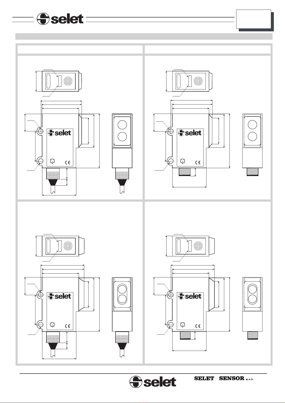
USCITA CONNETTORE M12 / M12 CONNECTOR OUTPUT
USCITA CAVO / CABLE OUTPUT
OCV51
DIMENSIONI MECCANICHE MECHANICAL SIZE
M12x1
M12x1 M12x1
M12x1
25
25
25
6
10 6
6
20
20
20
20
27
27
27
27
15
15
15
15
20
15
15
15 15
20
20
20
31
32
28
29
29
31
32
28
22
22
22
22
40
40
40
40
OCV51/CPNSCC01
OCV51/D2PNSCC01
OCV51/CPNSC
OCV51/D2PNSC
10-30 Vdc
10-30 Vdc
10-30 Vdc
10-30 Vdc
Iout 100 mA
Iout 100 mA
Iout 100 mA
Iout 100 mA
<1> BROWN +
<1> BROWN +
<1> BROWN +
<1> BROWN +
<4> BLACK OUT PNP
<4> BLACK OUT PNP
<4> BLACK OUT PNP
<4> BLACK OUT PNP
<2> WHITE OUT NPN
<2> WHITE OUT NPN
<2> WHITE OUT NPN
<2> WHITE OUT NPN
<3> BLUE -0V
<3> BLUE -0V
<3> BLUE -0V
<3> BLUE -0V
<5> RED NO/NC PROG
<5> RED NO/NC PROG
<5> RED NO/NC PROG
<5> RED NO/NC PROG
<2>
<2>
<2>
<2>
<3>
<3>
<3>
<3>
<5>
<5>
<5>
<5>
<4>
<4>
<4>
<4>
<1>
<1>
<1>
<1>
04F01
04F01
04F01
04F01
Out
Out
Out
Out
Teach-in
Teach-in
Teach-in
Teach-in
Good
read
Good
read
Good
read
Good
read
LED
LED
LED
LED
LED
LED
LED
LED
ø3,5
ø3,5 ø3,5
ø3,5
ø3,5
ø3,5 ø3,5
ø3,5
TASTEGGIO DIRETTO / DIFFUSE TYPE TASTEGGIO DIRETTO / DIFFUSE TYPE
RIFLESSIONE / REFLEX TYPE RIFLESSIONE / REFLEX TYPE
BARRIERA PROIETTORE - RICEVITORE
SENDER - RECEIVER BEAM TYPE
BARRIERA PROIETTORE - RICEVITORE
SENDER - RECEIVER BEAM TYPE
25
6
10
File Name: ocv51.cdr
Rev: 0.6
Turin / Torino - Piemont - Italy
E-mail: [email protected]
WEB: www.selet.it
La Ditta costruttrice si riserva di apportare qualunque modifica ritenga utile senza preavviso.
Manufacturer reserve itself all the rights to change without notice.
OCV51
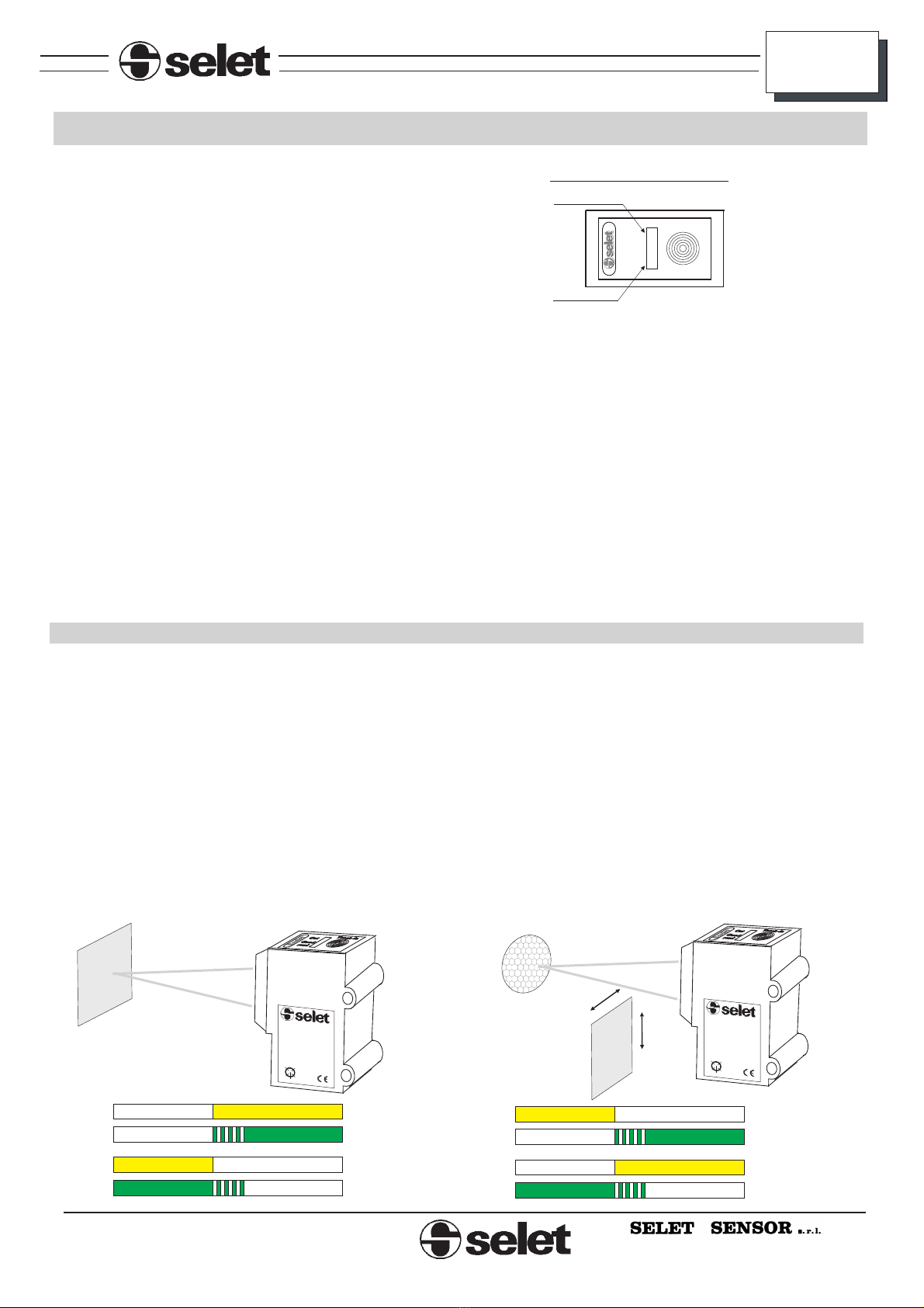
REGOLAZIONE DELLA SENSIBILITA’
FUNZIONAMENTO
DISTANCE SETTING
WORKING MODE
Occorre posizionare l’oggetto da rilevare (D2) o il
catarifrangente (C) davanti alla fotocellula.
La taratura avviene premendo per almeno un secondo il tasto
. Solo
al rilascio inizia la taratura. Se si preme il pulsante per un
tempo inferiore nulla viene cambiato.
Al termine della taratura il led verde potrà essere acceso fisso
entro le condizioni limite di funzionamento oppure potrà
essere lampeggiante o spento oltre tali condizioni. Il led giallo
invece seguirà lo stato dell’uscita: acceso per i modelli a
tasteggio, spento per i modelli a catarifrangente.
teach-in (trascorso tale tempo il led verde si riaccende)
First of all, it is necessary to position the object to detect
(D2)or the reflector (C) in front of the photocell.
The calibration is made by pushing the button for at
least one second (after this time the green led returns light on).
The calibration starts when the button is released. If you push
for a lesser time nothing will change.
At the end of the calibration the green led could be fixed on
inside the limits of functioning or could be blinking or be off
beyond that conditions. The yellow led will follows the output
status: light on for diffuse models light off for reflector
models.
teach-in
VISTA DALL’ALTO /TOP VIEW
La taratura è salvata su memoria non volatile, pertanto allo
spegnimento del sistema i dati memorizzati non vengono
persi.
The calibration is stored in eeprom memory, so on power off
data are not lost.
Collegando il filo rosso <5> (PROG) verso il ( ) ottengo un
funzionamento di tipo NO, verso il ( ) un funzionamento di
tipo NC.
+
-
Connecting the red wire <5> to ( ) the photocell works in
NO function mode, to ( ) in NC function mode
+
-
Il led giallo indica lo stato dell’uscita. Acceso allo stato
passante della fotocellula.
Il led verde indica la qualità del rilevamento: acceso fisso in
condizioni ottimali di lavoro, lampeggiante al limite della
capacità di rilevamento, spento in condizioni di non
rilevamento.
The yellow led shows the output status. It’s light on in the
detecting status of the photocell.
The green led shows the detecting quality: fixed on in
conditions of good read, blinking when it’s too near to the
switching point of the output , off when there aren’t reading
conditions.
Out Teach-in
Good
read
YELLOW LED
GREEN LED
Modelli a catarifrangente OCV51/C
Models with reflector OCV51/C
Put the reflector in front of the photocell at a distance within the
range: 20..2000 refering to a SCT2 reflector, 20..3000 mm to a
SCT4.
In the working mode if the reflector is in the correct range the
output will be off (yellow led off). If the reflector is beyond the
limits or if an object interrupts the infrared ray the output will
be on (yellow led on).
Posizionare il catarifrangente davanti alla fotocellula ad una
distanza compresa entro i seguenti limiti: 20..2000 mm riferito
ad un catarifrangente tipo SCT2, 20..3000 mm per il tipo SCT4.
Durante il funzionamento se il carter si trova entro i limiti
suddetti l’uscita risulterà spenta (led giallo spento). Se il carter
risulta oltre i limiti o se un oggetto interompe il raggio
infrarosso l’uscita risulterà accesa (led giallo acceso).
Modelli a tasteggio diretto OCV51/D2
Posizionare l’oggetto da rilevare davanti alla fotocellula ad una
distanza compresa entro i seguenti limiti: 10..400 mm riferito
ad un target di carta bianca opaca di 100x100mm.
Durante il funzionamento se l’oggetto da rilevare si trova entro
i limiti suddetti l’uscita risulterà attiva (led giallo acceso).
Oltre tali limiti l’uscita risulterà spenta (led giallo spento).
Diffuse models OCV51/D2
Put the object to detect in front of the photocell at a distance
within the range: 10..400mm referred to a white target paper
100x100mm.
In working mode if the object is in the correct range, the output
will be on . Beyond these limits the output will
be off (yellow led off).
(yellow led on)
OFF
NO
NC
OFF
ON
ON
ON OUT Led
OUT Led
ON Good Read Led
Good Read Led
OFF
OFF
OFF
NO
NC
OFF
ON
ON
ON OUT Led
OUT Led
ON Good Read Led
Good Read Led
OFF
OFF
Out Teach-in
Good
read
OCV51/D2PNSC
10-30 Vdc Iout 100 mA
<1> BROWN +
<4> BLACK OUT PNP
<2> WHITE OUT NPN
<3> BLUE -0V
<5> RED NO/NC PROG
<2>
<3>
<5>
<4>
<1> 04F01
Out Teach-in
Good
read
OCV51/CPNSC
10-30 Vdc Iout 100 mA
<1> BROWN +
<4> BLACK OUT PNP
<2> WHITE OUT NPN
<3> BLUE -0V
<5> RED NO/NC PROG
<2>
<3>
<5>
<4>
<1> 04F01
RIFLESSIONE / REFLEX TYPE
RIFLESSIONE / REFLEX TYPE
TASTEGGIO DIRETTO / DIFFUSE TYPE
TASTEGGIO DIRETTO / DIFFUSE TYPE
Taratura
Posizionare proiettore e ricevitore uno di fronte all’altro e alla
stessa altezza alla distanza desiderata. Tale distanza deve essere
compresa entro i limiti della capacità di rilevamento della barriera
(0,2-12m). La taratura deve essere eseguita in assenza di disturbi
esterni che potrebbero provocare errati comportamenti funzionali.
Se all'accensione si tiene premuto il pulsante sul proiettore, la
taratura ha inizio automaticamente al suo rilascio. In
tale fase, che è indicata dal led verde lampeggiante, aumenta la
potenza di emissione con tre diverse velocità. La taratura
automatica si può interrompere in qualunque momento premendo il
pulsante. Sul proiettore è inoltre disponibile un ingresso (filo nero),
che commutando (verso massa) arresta automaticamente la taratura
(si può collegare ad esso l’output NPN del ricevitore ). In questo
caso è necessario alimentare proiettore e ricevitore con la stessa
fonte.
La taratura invece si può effettuare in qualsiasi momento
durante il normale funzionamento della barriera, premendo il
pulsante per almeno un secondo. Se lo si tiene sempre premuto, la
taratura continuerà fino al rilascio del pulsante; altrimenti si può
procedere per step singoli. La taratura si può effettuare sia
incrementando la potenza di emissione (fase indicata dal led verde
normalmente acceso), che decrementandola (fase indicata dal led
verde normalmente spento). Per passare da incremento a
decremento bisogna premere il pulsante due volte consecutive
veloci (doppio click): il led verde cambierà stato. Se il proiettore è
in fase di decremento, dopo circa 15 secondi torna comunque
automaticamente in fase di incremento, in assenza di azioni da
parte dell’utente.
automatica
manuale
La taratura è salvata su memoria non volatile, pertanto allo
spegnimento del sistema i dati memorizzati non vengono persi.
Calibration mode
Put sender and receiver facing each other at the same height and at
the desired distance. This one must be included within the limits of
capability of detection of the barrier (0.2-12m). The calibration must
be done in absence of external noises that could cause bad working
behaviours. If the button on sender is kept pushed on system power
on, the automatic calibration automatically starts on its release. In
this mode, showed by the blinking green led, the emission power
increases with three different speeds. The automatic calibration can
be halted at any time pushing the button. Moreover on sender it is
available an input (black wire), that switching (to ground)
automatically stops the calibration (it is possible to connect to it the
NPN output of the receiver). In this case it is compulsory to supply
sender and receiver with the same source.
Instead the manual calibration can be done at any time during the
normal working mode of the barrier, pushing the button for at least
one second. If it is always kept pushed, the calibration will continue
until its release; otherwise it can be done by single steps. The
calibration can be done either increasing the emission power (stage
showed by the green led fixed on) or decreasing it (stage showed by
the green led off). To switch from increase to decrease, the button must
be pushed fast twice in a row (double click): the green led will switch
its status. If the sender is in the decrease stage, after about 15
seconds, anyway it automatically returns in the increase stage, in
absence of user’s actions.
The calibration is stored in eeprom memory, so on power off data are
not lost.
ISTRUZIONI PER L’USO INSTRUCTIONS FOR USE
File Name: ocv51.cdr
Rev: 0.6
Turin / Torino - Piemont - Italy
E-mail: [email protected]
WEB: www.selet.it
La Ditta costruttrice si riserva di apportare qualunque modifica ritenga utile senza preavviso.
Manufacturer reserve itself all the rights to change without notice.
OCV51
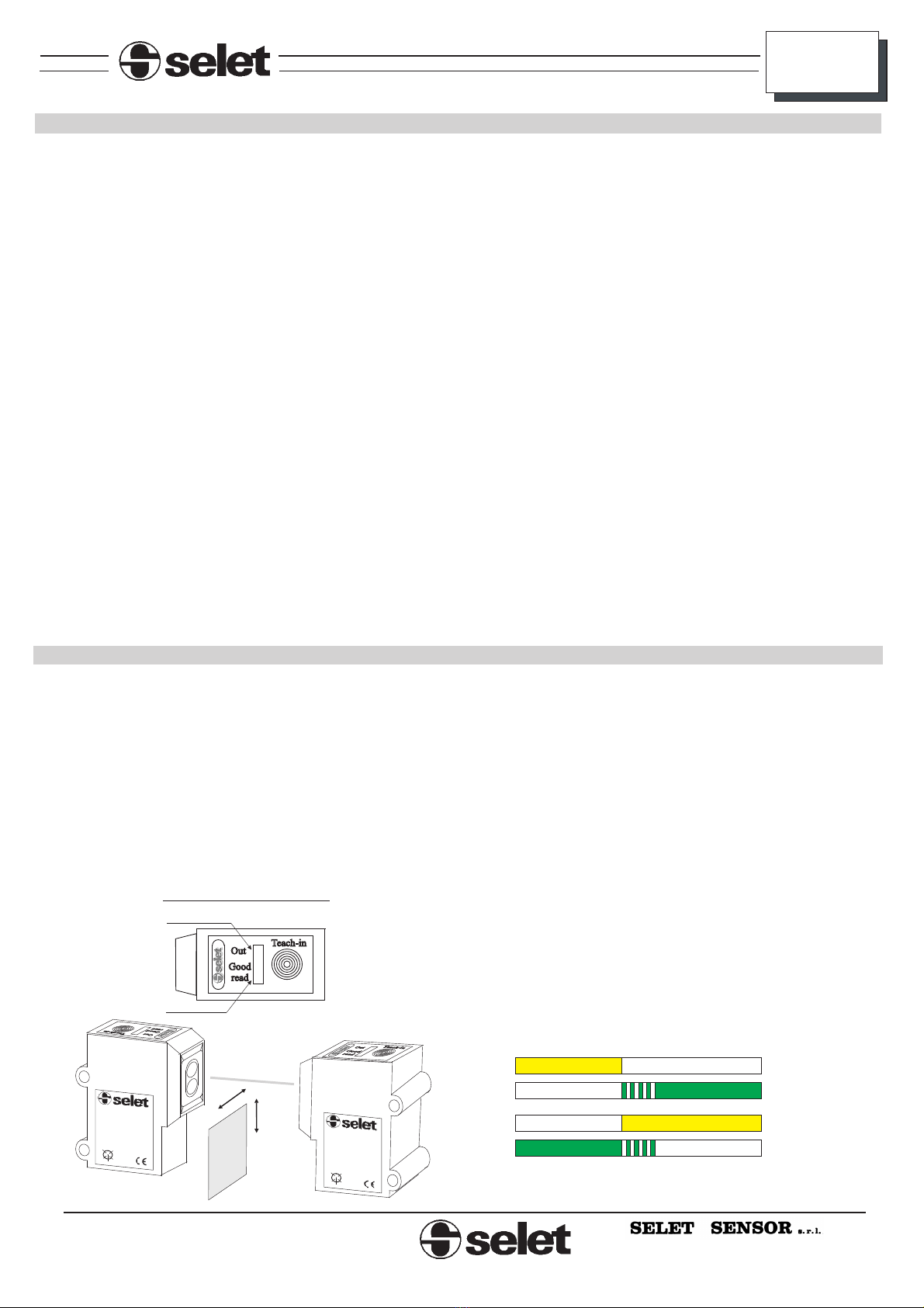
BARRIERA PROIETTORE - RICEVITORE/ SENDER - RECEIVER BEAM TYPE
In funzionamento, se l’oggetto da rilevare entra in zona di
rilevamento il led giallo del ricevitore cambia di stato secondo lo
stato dell’uscita e secondo la configurazione del filo di PROG.
sul proiettore indica una fase di normale
funzionamento. Sul ricevitore indica la qualità del rilevamento della
barriera: led acceso fisso indica condizioni ottimali di lavoro; led
lampeggiante indica condizioni non ottimali, al limite della capacità
di rilevamento della barriera. In questo caso si può procedere in tre
modi: o si posizionano meglio proiettore e ricevitore fino a quando
il led diventa fisso, o si esegue una nuova taratura automatica della
barriera, o si procede con quella manuale.
: sul ricevitore indica lo stato dell’uscita. Il led sarà
illuminato a barriera interrotta. Sul proiettore non è presente.
LED VERDE:
LED GIALLO
In working mode, if the object to detect enters the detection zone, the
yellow led changes its status according to the output status and
PROG wire configuration.
On sender it shows a normal working mode. On
receiver it shows the quality of detection of the barrier: a fixed on
led means optimal working conditions; a blinking led means not
optimal conditions, nearly beyond the capability of detection of the
barrier. In this case, three things can be done: to position in a better
way sender and receiver until the led becomes fixed on, to do a new
automatic calibration of the barrier or to do a manual calibration.
On receiver it shows the output status. The led will
be fixed on when the barrier is engaged. On sender it is not present.
GREEN LED:
YELLOW LED:
FUNZIONAMENTO WORKING MODE
Collegando il filo rosso <5> (PROG) del ricevitore verso il ( )
ottengo un funzionamento di tipo NO, verso il ( ) un
funzionamento di tipo NC.
+
-
Connecting the receiver red wire <5> (PROG) to ( ) the
photocell works in NO function mode, to ( ) in NC function
mode
+
-
VISTA DALL’ALTO /TOP VIEW
YELLOW LED
GREEN LED
Out Teach-in
Good
read
Out Teach-in
Good
read
OCV51/BPNSC OCV51/P
10-30 Vdc 10-30 Vdc
Iout 100 mA
<1> BROWN +<1> BROWN +
<4> BLACK OUT PNP <4> STOP CAL.
<2> WHITE OUT NPN <2> N.C.
<3> BLUE -0V <3> BLUE -0V
<5> RED NO/NC PROG <5> N.C.
<2> <2>
<3> <3>
<5> <5>
<4> <4>
<1> <1>
04F01 04F01
Out Teach-in
Good
read
OFF
NO
NC
OFF
ON
ON
ON OUT Led
OUT Led
ON Good Read Led
Good Read Led
OFF
OFF
BARRIERA PROIETTORE - RICEVITORE/ SENDER - RECEIVER BEAM TYPE

File Name: ocv51.cdr
Rev: 0.6
Turin / Torino - Piemont - Italy
E-mail: [email protected]
WEB: www.selet.it
La Ditta costruttrice si riserva di apportare qualunque modifica ritenga utile senza preavviso.
Manufacturer reserve itself all the rights to change without notice.
OCV51
TASTEGGIO DIRETTO
RIFLESSIONE
DIFFUSE TYPE
REFLEX TYPE
CONNETTORE/CONNECTOR
CONNETTORE/CONNECTOR
CAVO / CABLE
CAVO / CABLE
USCITA / OUTPUT
USCITA / OUTPUT
PNP + NPN SC
PNP + NPN SC
OCV51/CPNSC
OCV51/D2PNSC
OCV51/CPNSCC01
OCV51/D2PNSCC01
ø50mm
SCT2
ø80mm
SCT4
RIFERIMENTI CATARIFRANGENTI
RIFERIMENTI CONNETTORI PARTE VOLANTE
ELENCO PRODOTTI
REFLECTOR CODES
CONNECTOR LOOSE PART CODES
PRODUCT LIST
5 POLI / 5 POLES
DIRITTO / STRAIGHT
CAVO /
CEI 20-22 II - L=5m
CABLE
90°/90 DEGREES ANGLED CABLE OUTPUT
L110500 C110500
EMETTITORE
RICEVITORE
SENDER
RECEIVER
CONNETTORE M12/ M12 CONNECTOR
CONNETTORE M12/ M12 CONNECTOR
CAVO / CABLE
CAVO / CABLE
USCITA / OUTPUT
USCITA / OUTPUT
PNP + NPN SC
PNP + NPN SC
OCV51/P
OCV51/BPNSC
OCV51/PC01
OCV51/BPNSCC01

Turin / Torino - Piemont - Italy
E-mail: [email protected]
WEB: www.selet.it
La Ditta costruttrice si riserva di apportare qualunque modifica ritenga utile senza preavviso.
Manufacturer reserve itself all the rights to change without notice.
Altri prodotti
- interruttori di prossimità induttivi;
- interruttori di prossimità capacitivi;
- interruttori di prossimità magnetici;
- interruttori di prossimità fotoelettrici;
- connettori e cassette di connessione per sensori;
- encoder incrementali ed assoluti;
- alimentatori / interfacce per sensori;
- alimentatori da rete e da secondario per uso generico;
- voltmetri, amperometri, contagiri, visualizzatori a pannello;
- contaimpulsi mono e bidirezionali, contaproduzione, contagiri;
- termometri e termoregolatori
- schede logiche programmabili per uso OEM;
- pulsanteria e finecorsa meccanici;
Other products:
- inductive proximity switches;
- capacitive proximity switches;
- magnetic proximity switches;
- photo-electric sensors & proximity switches;
- connectors & connection boxes for sensor;
- incremental & absolute encoders;
- supply units / interfaces for sensors;
- power supply units for general purpose;
- voltmeters, ammeters, revolution counters, panel displays;
- counters mono & bi-directional, timers, revolution counters;
- thermometers & temperature controllers;
- OEM programmable logic cards;
- push-button & mechanical limit switches;
File Name: ocv51.cdr
Rev: 0.6
OCV51
Table of contents
Other SELET Accessories manuals


Popular Accessories manuals by other brands

Danfoss
Danfoss 088U0213 instructions

Silver Mountain Target
Silver Mountain Target T-SOLO Quick setup guide

HYDAC International
HYDAC International CS1000 Series programming

Bosch
Bosch BGS6235GB Instructions for use

Hagen
Hagen EXO TERRA PT2445 operating instructions

turck
turck RU D UPN8X2 Series quick start guide


