Overhead Volleyball Systems by
Copyright © 2014 Draper Inc. Form VB-OverheadSystems_Sub14 Printed in U.S.A.
Specifications—OVS-Overhead Volleyball Systems
Product Description
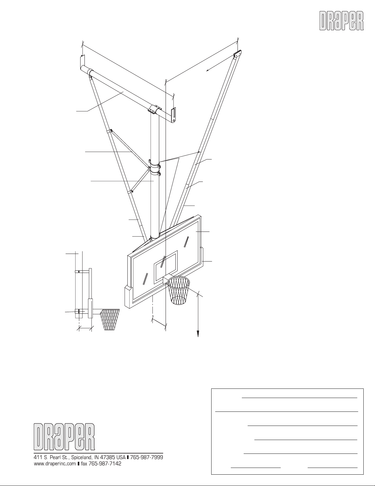
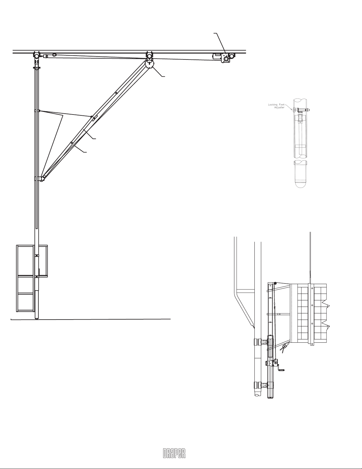
Overhead volleyball system shall be two independent, welded
support frames constructed from steel mechanical tubing. Each
main support frame shall have 4" OD 11-gauge front steel tubing
and formed 1½" OD 11-gauge back brace with ¼" x 2" HR steel
intermediate truss supports. Each support frame shall have stabiliz-
ing foot consisting of 3½" OD aluminum telescopic inner tube that
is lowered and locked into position using internal threaded rod and
gear assembly. Stabilizing foot shall be designed to provide supe-
rior rigidity and net tension. The bottom inner tube is provided with
a special spherical shaped, non-marking nylon end pad to protect
and minimize contact with floor should post be folded without feet
being raised. The main support frame shall pivot on 1¼" minimum
solid steel shaft secured in a milled bearing hole in ½" minimum
steel plate hangers to insure accurate positioning.
The folding side braces shall be jackknife type, fully adjustable, self-
locking in the down position and constructed of 2½" OD 13-gauge
(outer) steel tubing and 2¼" OD 14-gauge (inner) steel tubing. The
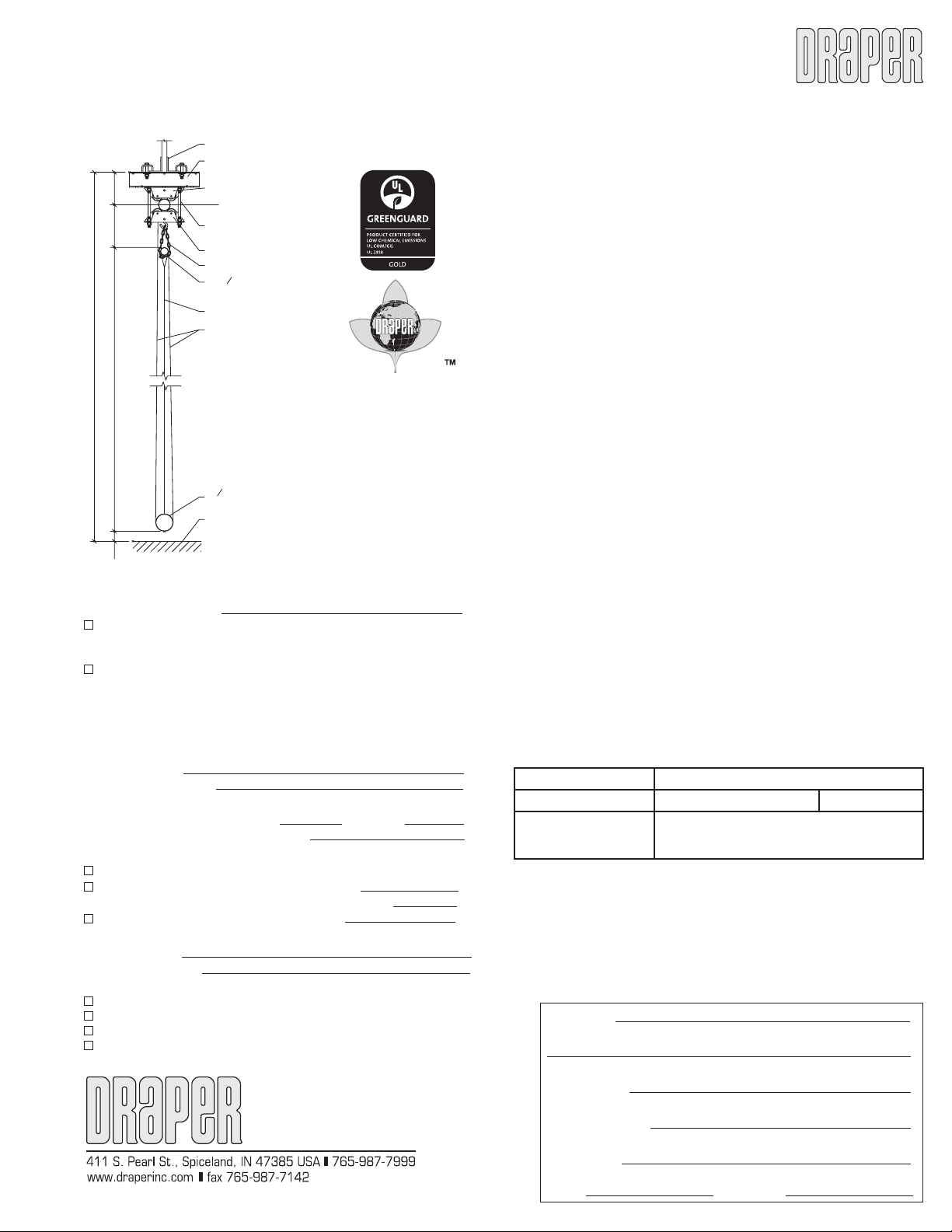
volleyball system shall be supported from 4" OD 11-gauge steel
mechanical tubing (as shown on plans) anchored to roof structure
by means of heavy steel support hangers. Superstructure tubes
shall be reinforced with bridging and/or bracing when truss centers
exceed 12'0". Support frame, folding braces and overhead super-
structure shall have a black or white powder coat finish. Optional
colors are available.
Volleyball system is raised or lowered by a ¼" (6.35 mm) aircraft
cable, certified minimum breaking strength of 7,000 pounds (3178
kg), operating over aluminum alloy sheaves with bronze bear-
ings that do not require lubrication. Cable is retracted by a Draper
#503285 ¾ HP, UL listed electric winch and includes Aut-O-Loc
2 Safety Straps. (See separate specification sheets for winch and
safety strap details.)
Each support frame shall have a telescoping net attachment post to
allow infinite height adjustment from 6' (1.854 m) to 8'4" (2.540 cm)
to meet all age group height settings from elementary school use
to international competition for both men and women. Posts shall
incorporate an internal threaded rod mechanism for easy, precise
and infinite height adjustments. Telescopic net attachment post
shall have a clear anodized finish and be constructed of a 3½" O.D.
(8.890 cm) schedule 80 outer aluminum tube, with a wall thickness
of .300" (.7620 cm). The inner telescoping adjustable tube shall be
2
7
/
8
" O.D. (7.303 cm) schedule 80 aluminum tube, with a wall thick-
ness of .300" (.7620 cm).
One net attachment post shall incorporate a heavy-duty, self-
locking worm gear mechanism (Net winch). Net winch shall be
furnished with a heavy 2" (5 cm) wide high tensile nylon strap with
heavy-duty snap hook to eliminate the possibility of hook break-
ing and guarantee safe connection to net top cable. The winch is
furnished with a folding handle for player safety.
Systems shall come complete with Draper Model 500014 Competi-
tion Volleyball Net. Net shall be 32' (9.75 M) long x 39
3
/
8
" (1 M) high.
Netting shall be high quality 4" square #36 black nylon cord with
vinyl coated polyester hem double stitched around entire perimeter
of net. Top hem of net shall be furnished with a 40'6" long x
1
/
8
"
diameter 2000 lb. minimum breaking strength galvanized aircraft
cable with a nylon coating (
3
/
16
" OD) to protect against fraying. Each
end of net cable has a loop with heavy swaged type fittings for easy
installation. Hems in end of net shall be furnished with a pocket
for use with a ½" diameter fiberglass dowel rod. Ends of net shall
PROJECT:
ARCHITECT:
CONTRACTOR:
SUPPLIER:
DATE: REVISED:
have six (three per end) 1" wide polypropylene tension straps with buckles for providing
additional tightening of net. Bottom of net shall be furnished with a ¼" diameter braided
white nylon rope equipped with a spring loaded, pressure type rope tensioner. Rope
Tensioner shall be Draper Model 500005. System also includes Draper Model 500016
Combination Antennas and Boundary Markers.
System shall be supplied complete with protection pads. Post sets shall include wrap
around pads hinged at corners to fold neatly around material to be padded. Two pads
shall be designed to wrap the main support frame to a height of 6’ 0” above the playing
surface. Upright pads to also wrap around the net attachment post sections including
the tensioning winch. Draper’s standard is for all pads to be wrapped with 14 oz., poly-
ester reinforced, dark blue vinyl. Other color pads are available including White, Marine
Blue, Brown, Red, Beige, Orange, Yellow, Grey, Maroon, Black, Purple, Forest Green,
Kelly Green or Navy Blue.
System can be provided with optional integral Judges Stand that is attached directly
to the main support frame. Judges Stand shall be constructed of 1½"x1½", 14-gauge
square steel tubing and 1" OD steel tubing, welded together. Legs, steps, platform, and
handrails shall all be one solid unit. Judges platform shall consist of ½" thick, polyure-
thane finished Birch plywood, permanently bolted to stand. Handrail/ladder section
shall be spaced vertically 16" on center with ladder steps spaced horizontally of 16"
centers. Judges stand shall be supplied complete with safety padding for player protec-
tion. Upper section of stand shall have a snapped into place 1½" polyethylene foam
padding. Lower ladder tubes shall have removable, hook and loop attached pads of 1"
neoprene foam. Standard pad color is dark blue, but same optional colors are available
as listed above.
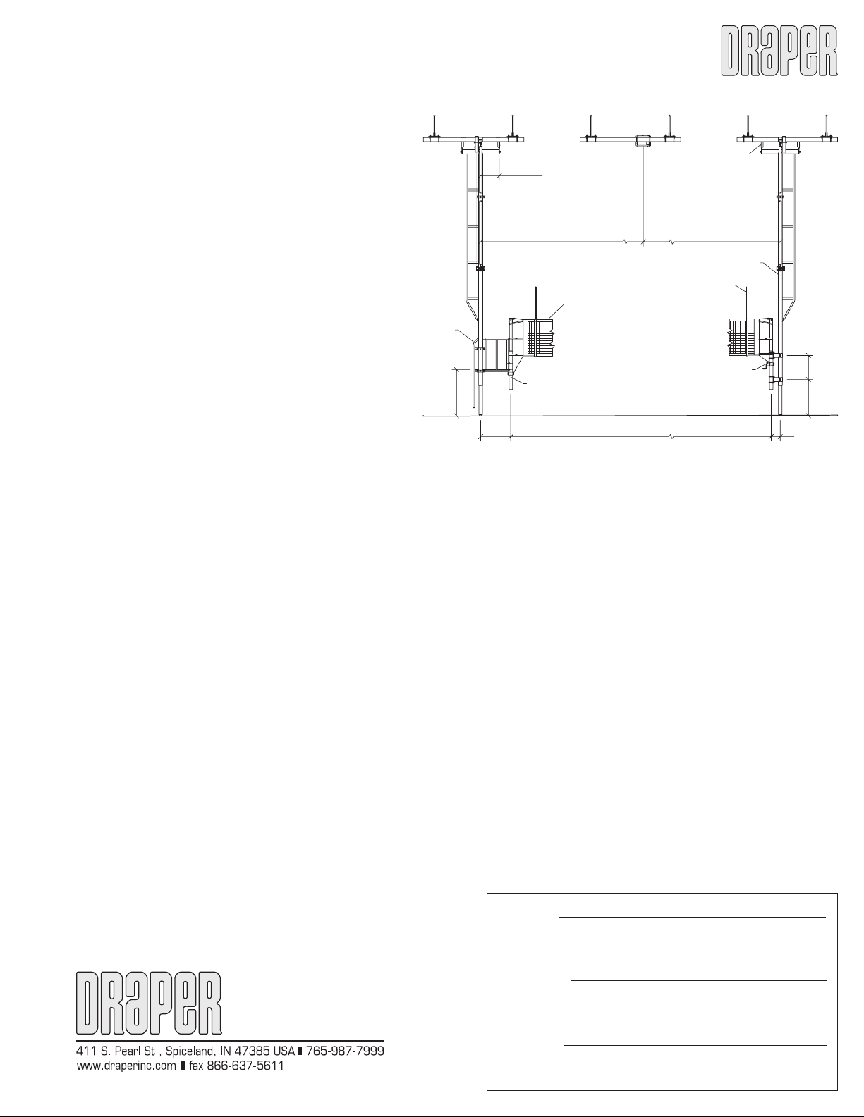
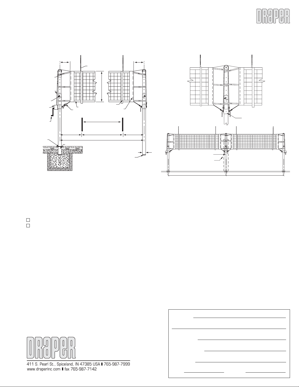
1'-6½"
Ty p.
19'-7½" 19'-7½"
Adjustable
T- Frame
Hanger
4" O.D. x 11 gauge
Tr ussed Frame
Antenna
Net Tensioning
Winch
Net Height
Adjustment
Men's Height: 7'-11
5
/
8
"
Women's Height: 7'-4
1
/
8
"
Middle School Height: 7'-4
1
/
8
"
Jr. High Height: 7'-4
1
/
8
"
Elementary Height: 6'-1"
36'-0"
2'-6" 9"
3'-10"
udges
Stand
3'-0" 2'-0"