SELT SILVER PLUS User manual
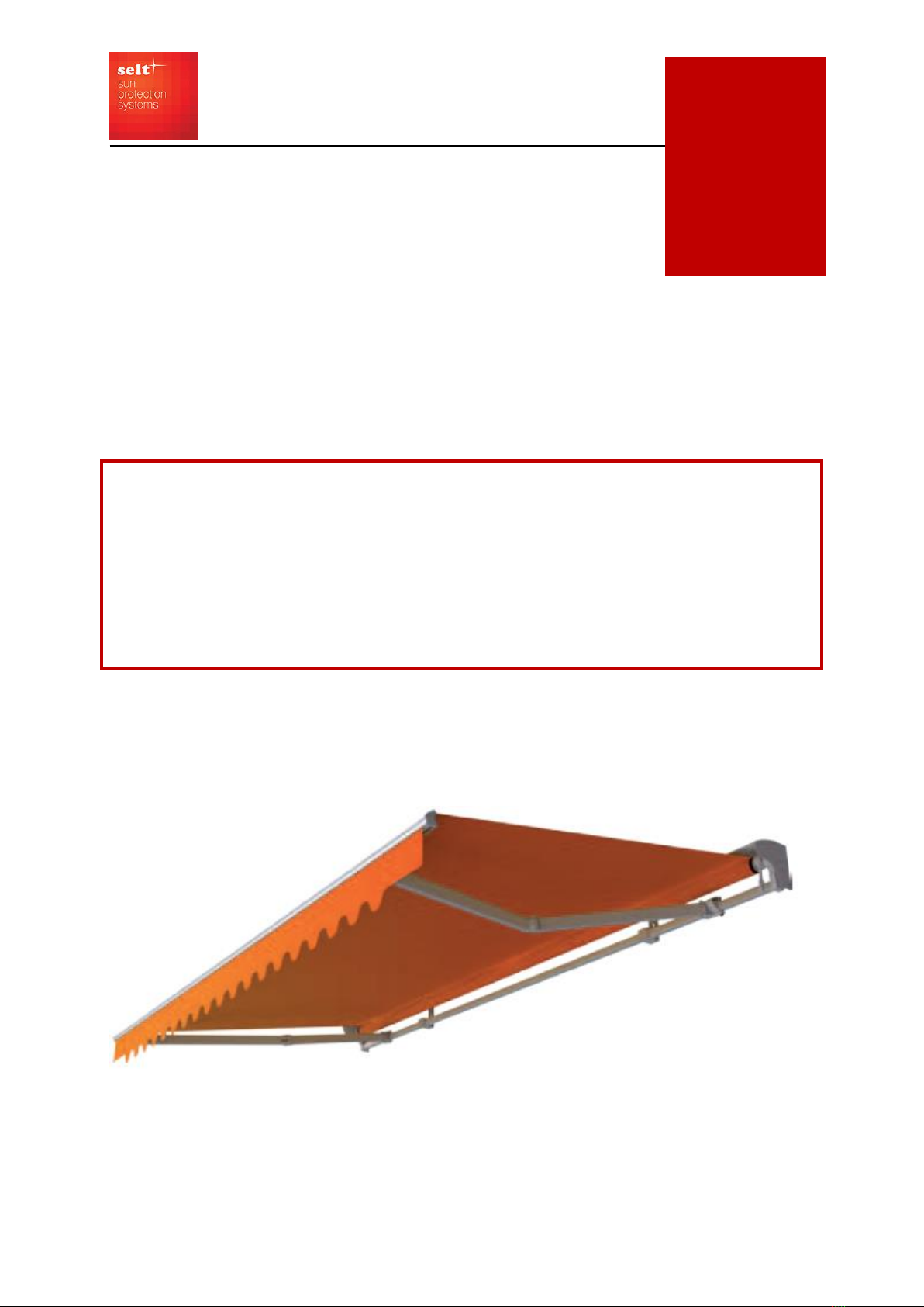
11. Awnings
11.2 Terrace awning SILVER PLUS
TECHNICAL AND OPERATIONAL DOCUMENTATION
INSTALLATION MANUAL,
OPERATING MANUAL AND INSTRUCTIONS FOR SAFE USE
(Translated from the original manual)
11.2
DT-E
DT-E 11.2 SUN PROTECTION SYSTEM –TERRACE AWNING PLUS
Edition 8/ March 2022 / EN
page 2 / 31
PRODUCT NAME:
TERRACE AWNING
SILVER PLUS
PRODUCT MANUFACTURER’S MARKING:
Manufacturer’s name:
SELT Sp. z o. o.
Manufacturer’s registered office:
45- 449 Opole, ul. Wschodnia 23A
Contact details:
Tel: +48 77 553 21 00 (secretariat)
Fax: +48 77 553 22 00
Website:
www.selt.com
E-mail:
PRODUCT SAFETY MARKING:
The product meets the CE safety requirements.
THIS TECHNICAL AND OPERATIONAL DOCUMENTATION:
Is valid from: 28 March 2022
Is applicable to the above listed product versions.

DT-E 11.2 SUN PROTECTION SYSTEM –TERRACE AWNING PLUS
Edition 8/ March 2022 / EN
page 3 / 31
TABLE OF CONTENTS
TABLE OF CONTENTS.................................................................................................................................................................. 3
1 INTRODUCTION................................................................................................................................................................ 4
1.1 SAFETY GUIDELINES FOR THE PRODUCT................................................................................................................. 4
1.2 EXPLANATION OF SYMBOLS AND SIGNS ................................................................................................................. 4
1.3 TERMS AND DEFINITIONS ....................................................................................................................................... 5
1.4 SUBJECT, INTENDED USE AND CONTENTS OF THE DOCUMENTATION................................................................... 5
2 PRODUCT TECHNICAL INFORMATION.............................................................................................................................. 6
2.1 TECHNICAL PARAMETERS ....................................................................................................................................... 6
2.2 PRODUCT SPECIFICATION ....................................................................................................................................... 6
2.3 SILVER PLUS AWNING CONSTRUCTION .................................................................................................................. 7
2.4 BRACKET TYPES....................................................................................................................................................... 7
3 TRANSPORT AND STORAGE OF THE PRODUCT ................................................................................................................ 8
3.1 COMPLETENESS AND QUALITY CONDITION OF DELIVERY ...................................................................................... 8
3.2 GENERAL CONDITIONS FOR TRANSPORT AND STORAGE OF THE PRODUCT .......................................................... 8
3.3 OBLIGATORY DESCRIPTIONS TO BE PLACED ON THE PRODUCT PACKAGING ......................................................... 8
4 PRODUCT INSTALLATION................................................................................................................................................. 9
4.1 REQUIREMENTS FOR SAFE INSTALLATION OF THE PRODUCT AT HEIGHTS............................................................. 9
4.2 PREPARATION FOR INSTALLATION........................................................................................................................ 10
4.3 GENERAL REQUIREMENTS FOR SAFE INSTALLATION ............................................................................................ 10
4.4 INSTALLATION TOOLS ........................................................................................................................................... 10
4.5 INSTALLATION....................................................................................................................................................... 10
4.5.1 SILVER PLUS AWNING INSTALLATION –WALL BRACKETS ............................................................................ 11
4.5.2 SILVER PLUS AWNING INSTALLATION –CEILING BRACKETS........................................................................ 16
4.5.3 SILVER PLUS AWNING INSTALLATION - ROOF RAFTER BRACKETS............................................................... 16
4.6 ELECTRIC DRIVE..................................................................................................................................................... 17
4.6.1 CONNECTION TO ELECTRICAL INSTALLATION ............................................................................................. 17
4.6.2 REMOTE OPERATION................................................................................................................................... 18
4.6.3 START-UP AND ADJUSTMENT...................................................................................................................... 18
4.7 MANUAL DRIVE..................................................................................................................................................... 18
5 SYSTEM OPERATION AND PRODUCT SAFETY................................................................................................................. 20
5.1 GENERAL REQUIREMENTS FOR OCCUPATIONAL HEALTH AND SAFETY................................................................ 20
5.2 SAFETY REQUIREMENTS RELATED TO SPECIAL CONDITIONS AND PLACES OF PRODUCT USE.............................. 20
5.3 OPERATIONAL SAFETY........................................................................................................................................... 20
5.4 CONTROL OF SAFE USE OF THE PRODUCT ............................................................................................................ 22
6 SYSTEM USE AND MAINTENANCE ................................................................................................................................. 23
6.1 USING THE PRODUCT IN ACCORDANCE WITH ITS INTENDED USE........................................................................ 23
6.2 INSTRUCTION FOR NON-PROFESSIONALS............................................................................................................. 23
6.3 TECHNICAL INSPECTIONS, MAINTENANCE AND REPAIR ....................................................................................... 23
6.4 USE OF AWNING FABRICS ..................................................................................................................................... 24
7 GENERAL WARRANTY TERMS ........................................................................................................................................ 26
7.1 WARRANTY EXCLUSIONS ...................................................................................................................................... 26
8 COMPLAINT / TECHNICAL DEFECTS ............................................................................................................................... 28
8.1 COMPLAINTS......................................................................................................................................................... 28
8.2 TECHNICAL DEFECTS ............................................................................................................................................. 28
9 PRODUCT DISASSEMBLY / UTILISATION / DISPOSAL...................................................................................................... 29
10 MARKING AND LABELLING OF THE PRODUCT WITH CE MARK...................................................................................... 30
10.1 PRODUCT COMPLIANCE WITH THE CE STANDARD .......................................................................................... 30
10.2 INFORMATION ACCOMPANYING THE CE MARKING ........................................................................................ 30

DT-E 11.2 SUN PROTECTION SYSTEM –TERRACE AWNING PLUS
Edition 8/ March 2022 / EN
page 4 / 31
1INTRODUCTION
1.1 SAFETY GUIDELINES FOR THE PRODUCT
The product has been manufactured in accordance with the latest technical knowledge in the field of construction and
manufacturing and meets the safety requirements in accordance with the following standards.
The safe construction of the product was achieved thanks to:
No.
Subject
European legal basis
Polish legal basis
1
External blinds. Performance
requirements including safety
EN 13561:2015
PN-EN 13561:2015
2
Construction Products
Regulation (CPR)
Regulation (EU) no 305/2011 of
the European Parliament and of
the Council
Act of April 16, 2004 on building products
DZ. U [Journal of Laws] 2004, No. 92, item
881 as amended of (Dz.U. [Journal of Laws]
2016.1570; 2015.1165; 2016.542)
3
Essential requirements for
machines
Directive 2006/42/EC of the
European Parliament and the
Council
Resolution of the Minister of Economy of 21
October 2008 DZ.U. [Journal of Laws] 2008
No. 199 item 1228) as amended (Dz.U.
[Journal of Laws] 2011.124)
Related documents: Declaration of Performance, Declaration of Conformity (only products with motor) and
instructions for installation, use of motors and control.
1.2 EXPLANATION OF SYMBOLS AND SIGNS
The following symbols (pictograms) indicate particularly important threats and safety information.
Pictogram
Pictogram meaning
Information
INFORMATION
Prior to using the product, its operating manual should be read.
Following the operating manual guarantees:
- failure-free use of the product,
- warranty coverage against product defects
Keep the operating manual for safety of people.
INFORMATION
No harmful or dangerous consequences for people or facilities.
NOTE!
A situation likely to cause product damage or other damage.
No threat for people.
WARNING!
Threat of danger
DANGER!
This symbol marks all safety information which, if not observed, could endanger
the life or health of persons. Health or life hazard. Risk: danger of serious injury
or death. Unsafe operation that may cause injury or damage to the product.
WARNING!
Threat to human life or health due to electric shock.
ENVIRONMENT
Marking of electronic or electric equipment, which should be collected in the
designated points.
DT-E 11.2 SUN PROTECTION SYSTEM –TERRACE AWNING PLUS
Edition 8/ March 2022 / EN
page 5 / 31
1.3 TERMS AND DEFINITIONS
For the purposes of this documentation the following terms and definitions shall apply:
AWNING: Terrace awnings, as external sun protection screens are installed solely on the outside of the building for
protection from sun light for terraces, restaurant patios, balconies, shop windows etc. Rolling up and down of the awning
fabric is performed with the use of an electric control mechanism or manual crank.
AWNING FABRIC: Part of the product serving for protection from sun light, but also having a decorative function.
Manufactured from high quality materials is put into motion with manual or electric control mechanism, assuring the
product fulfills its function.
1.4 SUBJECT, INTENDED USE AND CONTENTS OF THE DOCUMENTATION
This documentation covers the products manufactured by SELT Sp. z o.o.
This documentation applies to all types of terrace awning SILVER PLUS.
User’s manual and instructions for safe use, with motor manual, should be handed over to the end
user.
IMPORTANT INSTRUCTION RELATED TO SAFETY
WARNING - IT IS VERY IMPORTANT TO PROCEED ACCORDING TO THIS MANUAL
TO ENSURE PEOPLE SAFETY.
KEEP THIS MANUAL
The documentation is valid jointly with the information concerning a specific product, which is available
on the website www.selt.com
This documentation includes:
important recommendations concerning product installation, use and maintenance.
important recommendations concerning product transport and storage.
tips following which will assure long-time and fault-free use of the product.
SELT SP. Z O.O. shall not bear responsibility for damage resulting from failure to follow recommendations included in the
documentation.
In order to further improve the product, SELT SP. Z O.O. reserves the right to introduce changes which, while maintaining
the essential technical parameters, shall be deemed purposeful for improving product operation quality and safety of use.
SELT SP. Z O.O. with a head office in Opole shall hold the copyrights to this documentation. The documentation cannot be
used without permission, either partially or as a whole, for any concurrent business activity nor can it be made available to
third parties.

DT-E 11.2 SUN PROTECTION SYSTEM –TERRACE AWNING PLUS
Edition 8/ March 2022 / EN
page 6 / 31
2PRODUCT TECHNICAL INFORMATION
Technical specifications of the product are available after logging in on website www.selt.com
2.1 TECHNICAL PARAMETERS
TERRACE AWNING SILVER PLUS
Projection:
1,6 m; 1,9 m; 2,2 m; 2,5 m
Maximum projection
2,5 m
Minimum width
Projection + 0,4 m or
with overlapping arms: projection –0,4 m
Maximum width
5,3 m
Roller tube diameter
70/78 mm
Arms*
Folding, aluminium, with springs and Flyer’s chain.
Possibility of using cross arms.
Tilt angle
5° - 40°
Optional hood
Yes
Manual drive
Crank 1,5 m; 1,8 m; 2,2 m
Electric drive
Motor, motor with emergency override, remote control
receiver, weather sun-wind automation
Construction colour
White
Fabric
c. 150 patterns
Valance**
3 shapes according to the template –shape modulus of D
and C variable due to different system widths; standard
height 21 (± 0,5cm), max. non-standard height 40 (± 0,5cm)
or straight 50 (± 0,5cm)
Application
External
Mounting brackets
Wall, ceiling, roof rafter
* - in the case of a non-standard valance over 21 cm, there is a likelihood of abrasions / damages related to its longer length (e.g.
abrasions against the facade, greater susceptibility to wind blows, etc.)
- in type C and D valances, depending on their width and type of fabric,
the technology may cause the lack of the "wave" effect at its ends.
The tolerance of the dimensions of the awning width is ± 2cm
Due to technological reasons, slight differences in colour shade are deemed acceptable and they are not a ground for
complaint.
Detailed data on the parameters of individual motors are available on the websites of motor manufacturers and on the
website:
www.selt.com
→
OUR OFFER
→
MOTOR,
ELECTRIC,
EQUIPMENT
The optional use of weather automation additionally protects the product against changing
weather conditions.
2.2 PRODUCT SPECIFICATION
Products manufactured by SELT Sp. z o. o. have appropriate technical and operational parameters.
They have the following features:
They provide excellent sun protection for surfaces such as terraces and balconies.
They protect against intense solar radiation.
They are aesthetic and durable structures.
Thanks to the simple construction and solid realization, they are used in commercial areas.
The motors have an IP 44 degree of protection, which means that they are protected against water splashing onto the
casing from any direction.
Increased functionality thanks to the use of wind and solar automation and radio control.
Awning fabrics manufactured on the basis of high-quality materials, covered with an impregnation that constitutes a
protective barrier and increases resistance to dirt.

DT-E 11.2 SUN PROTECTION SYSTEM –TERRACE AWNING PLUS
Edition 8/ March 2022 / EN
page 7 / 31
2.3 SILVER PLUS AWNING CONSTRUCTION
2.4 BRACKET TYPES
Wall bracket
Ceiling bracket
Roof rafter bracket
Option with hood

DT-E 11.2 SUN PROTECTION SYSTEM –TERRACE AWNING PLUS
Edition 8/ March 2022 / EN
page 8 / 31
3TRANSPORT AND STORAGE OF THE PRODUCT
3.1 COMPLETENESS AND QUALITY CONDITION OF DELIVERY
SELT Sp. z o. o. makes every effort to ensure that the goods comply with the order. However, checking the completeness of
the product is the responsibility of the Buyer and should take place at the time of its receipt.
Any discrepancies should be immediately reported to the driver/warehouseman/assembly team and marked in the
acceptance report or on the WZ document under pain of loss of claims in this respect. Checking the quality in terms of
obvious defects is the responsibility of the Buyer and should take place at the time of receipt of the goods. Apparent
defects are mechanical damage, scratches, cracks, etc.
Quantitative discrepancies and possible replacement of parts with obvious defects SELT Sp. z o. o. undertakes to
supplement or replace it in the shortest possible time.
3.2 GENERAL CONDITIONS FOR TRANSPORT AND STORAGE OF THE PRODUCT
List:
The product is factory-packaged in a cardboard box to protect it from damage during storage, transport and
transport to the place of final assembly,
products for transport/storage should be set in accordance with the arrows indicated on the product packaging,
do not stack the products in more than two (2) layers because the packing material can be crushed, what in turn
may lead to permanent damage to the product,
products places on means of transport should be protected against relocation and damage during the transport
(e.g. with distance pieces, protecting belts etc.),
during transport the product should be protected against rain or snow,
storage locations should be dry, well-ventilated and protected against harmful impact of the weather (sun, rain,
etc.),
if product weight exceeds 25 kg its relocation to the final installation location should be carried out by at least two
persons.
3.3 OBLIGATORY DESCRIPTIONS TO BE PLACED ON THE PRODUCT PACKAGING
Prior to installation and use of the product please read carefully the operation and
maintenance manual available at the following website: https://www.selt.com/dte-en

DT-E 11.2 SUN PROTECTION SYSTEM –TERRACE AWNING PLUS
Edition 8/ March 2022 / EN
page 9 / 31
4PRODUCT INSTALLATION
This chapter contains general requirements concerning the product installation.
Correct assembly is a necessary condition for smooth operation of the product. SELT Sp. o.o. recommends using only
professional assembly crews, which guarantee the Purchaser that the conducted installation will be correct.
General requirements for safe installation
it is necessary to observe general rules of good building practice,
it is necessary to comply with applicable Occupational Health and Safety regulations concerning in particular
those applying to the safety of operation of electrical equipment and work on heights,
The product must be fixed mechanically (foams, adhesives or similar materials are not allowed as fixing
materials).
The product should be fixed to durable elements of the building (walls, lintels, steel structure, aluminum
structure, window joinery).
The base to which the wall and ceiling brackets of the product will be attached should be a solid structure
(concrete, brick, etc.).
Do not mount the product on elements that do not provide adequate load-bearing capacity.
Installation is made to even, dry wall surfaces with appropriate strength, made in accordance with the general
principles of building art.
In the case of metal structures joined together in accordance with the applicable rules for joining metals,
assembly is made to materials with appropriate wall thickness.
Before starting the assembly, remove all unnecessary elements from the assembly area.
Before starting the assembly, all mechanisms necessary for the operation of the drive should be immobilized.
Technical information
The manufacturer allows the installation of the product in the following types of substrate (wall bearing layer):
- reinforced or unreinforced concrete, class at least C20/25, non-cracked,
- concrete specified above having a layer of insulation with a thickness of up to 25 cm,
- wall at least 24 cm, of Mz solid bricks, NF format, with a strength of at least 20 MPa and a density of >1.8 kg/dm3
based on M2.5 - M9 mortar,
- wall at least 24 cm, of silicate blocks with a strength of at least 10 MPa and a density of >2 kg/dm3 based on M2.5 -
M9 mortar
- wall at least 17.5 cm, of silicate perforated blocks with a strength of at least 20 MPa and a density of >1.4 kg/dm3
based on M2.5 - M9 mortar
- wooden (wall/ceiling) beams, class of at least C24, without cracks, with a thickness of at least 100 mm
- wooden rafters, class of at least C24, without cracks, with a thickness of at least 70 mm
- walls made of silicate blocks (full or hollow) with a layer of insulation –to be consulted with an authorised designer,
- solid brick walls with a layer of insulation - to be consulted with an authorised designer,
- wall made of cavity ceramic hollow bricks without insulation or with a layer of insulation - to be consulted with an
authorised designer
- aerated concrete blocks - this substrate is not recommended.
The above list of substrates is only indicative. Each substrate suitability depends on the specific location and size of the
product, and must be selected by an authorized constructor.
4.1 REQUIREMENTS FOR SAFE INSTALLATION OF THE PRODUCT AT HEIGHTS
Product installation, due to a necessity of execution of works on heights, is classified to the particularly
hazardous works because it causes high risk of occurrence of threats for human health and safety - in
particular in case of fall from heights.
Obligation to ensure preparation of occupational health and safety plan during installation should be fulfilled by the
Purchaser. It is the Purchaser's responsibility to develop a health and safety plan during assembly. During assembly, the
Purchaser should comply with the health and safety regulations related to work at height, in particular:
direct supervision of execution by person appointed for this purpose (e.g. site manager, foreman),
proper protection equipment, in particular equipment protecting against fall from heights,

DT-E 11.2 SUN PROTECTION SYSTEM –TERRACE AWNING PLUS
Edition 8/ March 2022 / EN
page 10 / 31
detailed guidance for employees working at heights,
the need to use: ladders with appropriate quality and safety certificates, scaffolding, safety clamps, platforms
with adequate resistance to the expected load.
Work at heights requiring the use of personal protective equipment against falls from a height must be carried out by at
least 2 people.
4.2 PREPARATION FOR INSTALLATION
unpack the product and check if there are all components necessary for assembling,
prior to installation you should check whether the substrate has sufficient load capacity allowing safe assembly
and operation,
prepare a set of tools needed for self-assembly.
4.3 GENERAL REQUIREMENTS FOR SAFE INSTALLATION
To avoid the risk of hand and fingers harm during opening and closing of the awning, the awning should be
installed on such height so that the lowest element of the awning after it is opened is at least 2200mm above the
ground,
The product should be protected against any stains made by e.g. silicon, mortar or mounting foam, which may
cause its damage,
Using any chemical substances containing bituminous substances or any other substances making reactions with
the product is forbidden,
In case of installation in public places, e.g. hospitals, schools, bording schools etc. The placement of
switch/remote control device should be marked according to health and safety regulations,
In case of remotely operated awning, bracket for remote control should be installed in place not available for
children,
Electrical installation, first programing of motor and specialized service can be conducted solely by specialized
service companies.
As a standard, the awning is packed in bubble wrap, in critical places protected with polyurethane foam in
biodegradable foil, and the whole thing is packed in a multi-layer cardboard box in the position corresponding
to the awning attached to the wall. The awning can only be transported in this way. Another form of
transport may result in shifting the internal balance supports in the cassette and as a result in the appearance
of dark lines along the seams of the fabric.
Improper installation may cause hazardous situation for the user.
4.4 INSTALLATION TOOLS
drills
hammer drill,
ladder/scaffolding,
screwdriver,
hammer
measure tape,
pencil/marker,
spirit level,
ring/flat wrenches,
Allen keys,
anchors.
4.5 INSTALLATION
Instructions for assembly, operation and safe use are available after logging in on website www.selt.com

DT-E 11.2 SUN PROTECTION SYSTEM –TERRACE AWNING PLUS
Edition 8/ March 2022 / EN
page 11 / 31
SELT recommends the use of Fischer fixing products - selected depending on the type of substrate. Suggested
recommendations for selected substrates:
a) for non-cracked concrete class C20/25 and not higher than C50/60:
M10x110 A4 anchors set on injection mortar (Fischer FIS A M10x110 A4 anchors on FIS V resin or an equivalent
product from another manufacturer is recommended)
Insertion depth in concrete 80 mm
Distance from anchor axis to base edge: min. 45 mm in case of M10 anchor
Minimum base thickness is 150 mm for M10 anchor
b) for Porotherm wall with insulation max. 15 cm:
Thermax 16/170 M12 anchors with 20x200 sleeve mesh, embedded in injection mortar (Fischer FIS V resin)
c) for walls with solid brick or concrete with insulation max. 15 cm:
Thermax 16/170 M12 anchors embedded in injection mortar (Fischer FIS V resin)
The required number of wall brackets depends on the length "L" of the awning:
It is recommended to mount the outer wall brackets at a distance of 20 to 45 cm from the ends of the awning, and place
the remaining brackets at equal intervals.
1) Prepare installation
tools according to the list.
2) Start the installation with marking
installation spots for wall brackets.
Level the bracket vertically with spirit
level and mark places for installation
holes.
3) Drill holes in the
marked places.
4) Fix installation
anchors.
4.5.1 SILVER PLUS AWNING INSTALLATION –WALL BRACKETS

DT-E 11.2 SUN PROTECTION SYSTEM –TERRACE AWNING PLUS
Edition 8/ March 2022 / EN
page 12 / 31
5) Screw the wall bracket in the position as shown in the drawing in the available variants using: the upper and lower
holes. Follow the anchor manufacturer's instructions regarding required anchor spacing, preparation and installation
method.
6) Based on the first installed bracket
(base) mark installation places for
remaining ones –pay paticular
attention so that brackets are
installed at the same horizontal level
and in the same plane.
7) Drill holes in marked places.
8) Fix installation anchors.
9) Install the remaining wall brackets in accordance with point 5.
10) Slide the awning (cassette) on wall brackets so that the construction is maximally pressed to the back (Note –
before placing the awning verify the alignment of brackets –wall surface should be of the same thickness at
installation spots).
DT-E 11.2 SUN PROTECTION SYSTEM –TERRACE AWNING PLUS
Edition 8/ March 2022 / EN
page 13 / 31
11) Secure square bar with M8x65 screws and put PVC cover on them.
12) Open the awning slightly.
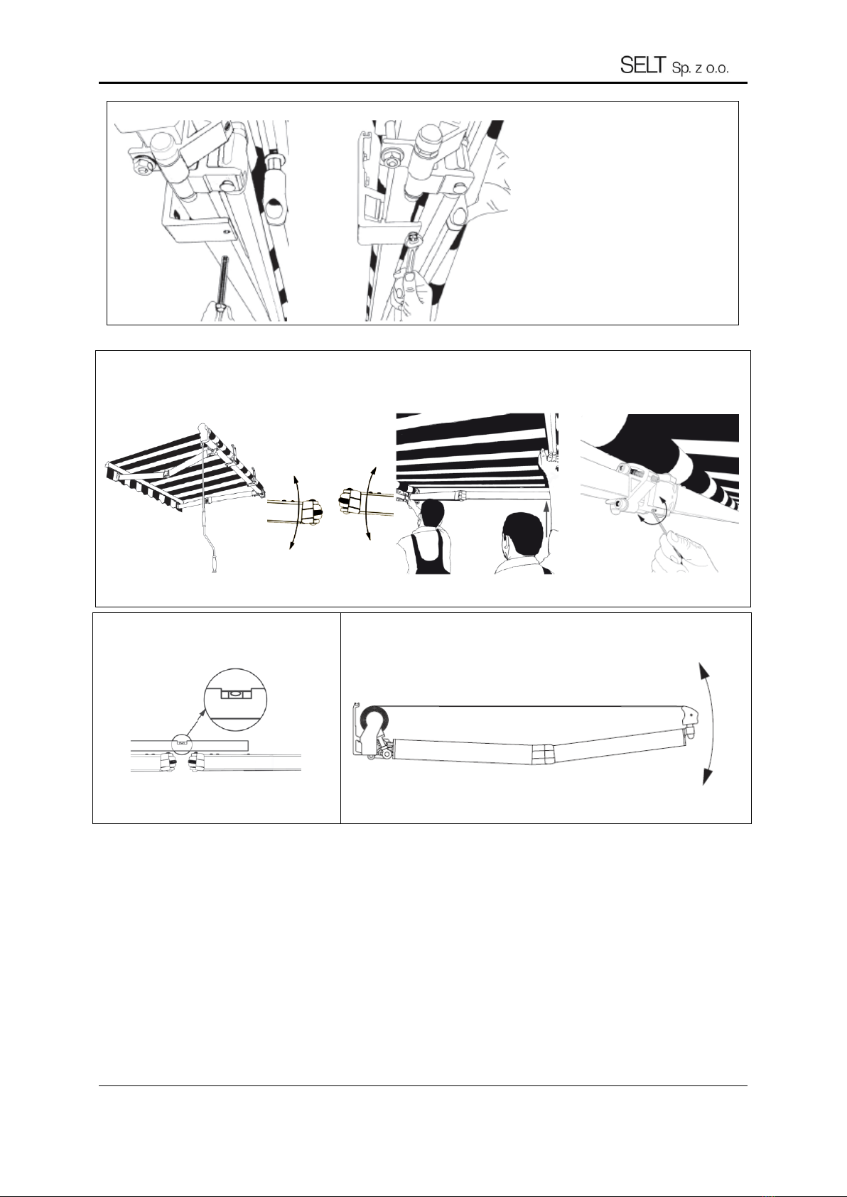
13) If necessary adjust the arm level by loosening or tightening the internal screw in arm brackets.
14) With spirit level check if the arms close
to one plane.
14) Open the awning completely.
DT-E 11.2 SUN PROTECTION SYSTEM –TERRACE AWNING PLUS
Edition 8/ March 2022 / EN
page 14 / 31
15) To change the tilt angle of the awning use an Allen wrench to loosen
(increase the tilt angle) or tighten (decrease the tilt angle) adjusting screws (with
button-heads) of the arm brackets
16) With spirit level check if front bar is
levelled horizontally.
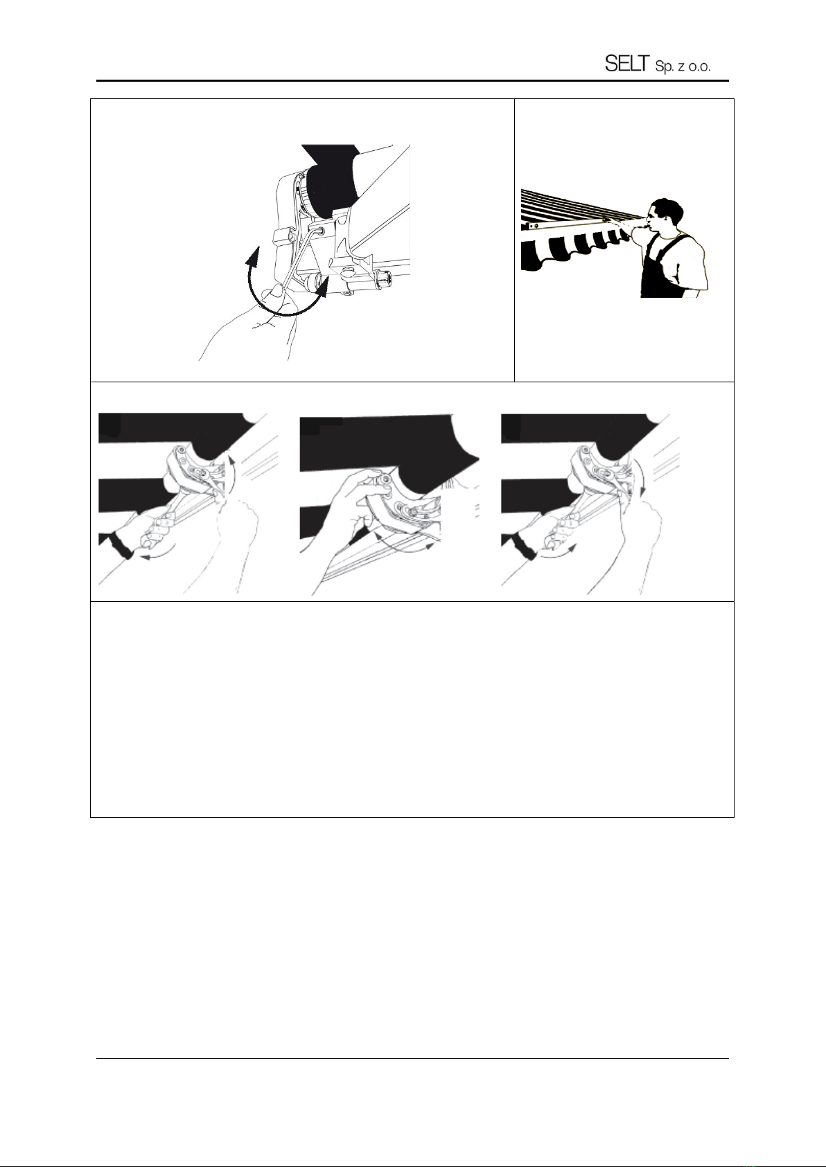
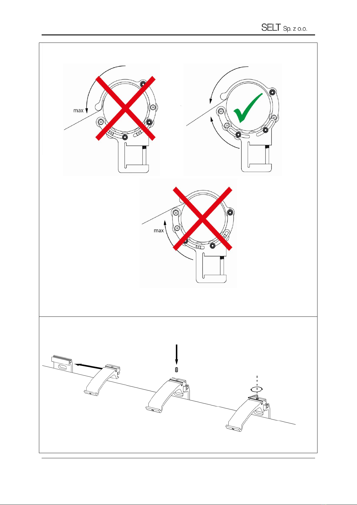
18) After changing the tilt angle, remember to modify the position of the roller tube support.
The half-rings of the roller tube support should be adjusted in accordance with the pictorial manual (below).
WARNING! It must be remembered that when changing the tilt angle of the awning, each time the position of the half-rings
of the roller tube support must also be adjusted properly.
DT-E 11.2 SUN PROTECTION SYSTEM –TERRACE AWNING PLUS
Edition 8/ March 2022 / EN
page 15 / 31
19) VERSION WITH HOOD (ONLY WALL MOUNTING OPTION)
In order to attach the hood to the awning, please carry out the following steps (in sequence as shown on the drawings
below).

DT-E 11.2 SUN PROTECTION SYSTEM –TERRACE AWNING PLUS
Edition 8/ March 2022 / EN
page 16 / 31
Brackets should be installed in the same order and manner as wall brackets.
It is recommended to install the extreme ceiling brackets at a distance of 20 to 45 cm from the ends of the
awning, the remaining ones should be placed at equal intervals.
Make sure that ceiling brackets are aligned, i.e. in the same distance from the wall.
To the installed ceiling brackets install wall brackets with set of M10x35 screws with washers and nuts. Slide the
awning on wall brackets so that the construction is maximally pressed to the back.
Secure square bar with M8x65 screws and put PVC cover on them.
Roof rafter brackets should be installed to roof rafters the closest to awning edge possible (it is recommended to
install them at a distance of 20 to 45 cm from the ends of the awning), remaining brackets place in equal intervals.
Brackets should be installed in the same order and manner as wall brackets.
Secure the roof rafter bracket using scrws for wood or bolts.
4.5.2 SILVER PLUS AWNING INSTALLATION –CEILING BRACKETS
4.5.3 SILVER PLUS AWNING INSTALLATION - ROOF RAFTER BRACKETS

DT-E 11.2 SUN PROTECTION SYSTEM –TERRACE AWNING PLUS
Edition 8/ March 2022 / EN
page 17 / 31
Based on the first installed roof rafter bracket (base), mark the places where the remaining roof brackets will be
installed - pay special attention that the mounted roof rafter brackets are in one line, i.e. at the same distance
from the end of the rafters.
Remember to install left and right roof rafter bracket alternatively, i.e. starting from awning right edge (looking at
the awning from the front).
To the installed roof rafter brackets install wall brackets with set of M10x35 screws with washers and nuts. Slide
the awning on wall brackets so that the construction is maximally pressed to the back. Secure square bar with
M8x65 screws and put PVC cover on them.
4.6 ELECTRIC DRIVE
The installation must be performed by an electrician possessing appropriate permissions and professional experience. The
connection should be made in accordance with the previously elaborated, individual electric diagram and according to the
motor manual. There is a possibility of individual and group control with one or multi channel remote control. Transmitters
and receivers should be programmed according to the instructions attached to the motor.
When the awning starts working special attention should be paid to correct rolling up and down of the fabric and proper
functioning of limit switches in the motor.
List of steps:
connection to the electrical supply system,
connection to the electrical control system.
After the product is installed one may proceed to connecting the drive and control system to the previously prepared
systems: power supply and control systems. Connection to the power supply system should be made in accordance with
the previously elaborated individual electric diagram, including fire protection regulations.
The connection must take into account the environmental conditions in which the product will be used. The connection
must be made by a licensed electrician.
The electrical connection and setting of the motors must be carried out in accordance with the instructions of the motor
manufacturers.
The instructions are attached to the product and are also available on the websites of motor manufacturers and on the
website:
www.selt.com → OUR OFFER → MOTOR, ELECTRIC, EQUIPMENT
Environmental conditions with increased risk:
environments with increased risk include bathrooms and showers, kitchens, garages, cellars, saunas, rooms for pets,
operating blocks of hospitals, hydrophores, heat exchangers, spaces limited by conductive surfaces, campsites, open areas,
etc.
In rooms and spaces with increased risk conditions, automatic devices should be used to turn off the power supply to the
damaged product, e.g. residual current devices. It is recommended to use in bathrooms, kitchens, garages and basements.
Must be used in swimming and shower pools, saunas, on construction sites, when powering outdoor devices, in farms and
horticulture, in camping and recreational vehicles and in rooms at risk of fire.
Residual current devices are only supplementary protection from direct contact, they cannot be the only means of
protection. The goal of their application is to supplement the protection in case other means of protection from direct fail
or in case of user’s carelessness.
During installation attention should be paid to usage safety rules, e.g. minimum height electrical appliances can be installed
at.
General guidelines for safe connection:
The connection must be performed by electrician possessing appropriate permissions and experience,
During connection health and safety regulations should be observed,
Electrical connection and adjustment of motors should be performed according to the motor manufacturer’s
manual added to the product
4.6.1 CONNECTION TO ELECTRICAL INSTALLATION

DT-E 11.2 SUN PROTECTION SYSTEM –TERRACE AWNING PLUS
Edition 8/ March 2022 / EN
page 18 / 31
pay attention to the correct position of the power cable at the entrance to the product so that the water may be
drained and flow down the cable.
Incorrect connection of the motor can lead to product damage or create a hazardous situation.
The motors have thermal switches that turn off the drive after a few minutes of continuous
operation to protect against overheating. After switching off by the thermal protection, wait an
appropriate time depending on the type of motor and ambient temperature (several minutes) to be
able to restart it.
Remote operation programming (assigning remote control appliances, weather sensors and other operation elements)
should be performed according to the manufacturer’s manual added to the product. The method of using the motors is
included in a separate instruction manual, as well as on the manufacturer's website.
The product may be damaged if the central control does not function properly.
An interruption in the power supply or a failure of the installation may cause the central control to malfunction.
Awning motors are not designed for continuous operation. The integrated overheating protection shuts down the
motor after a few minutes of continuous operation. The motor restarts after several minutes. This is the time it
takes for the motor to cool down. This time depends on the ambient temperature.
Recommendations and actions:
extreme position (up and down movement of the fabric) are protected by limit switches that needs to be adjusted
during the installation,
person performing the adjustment of extreme positions should possess adequate electrical permissions,
knowledge and experience,
adjustment of limit switches must be done in accordance with motor’s maintenance manual,
prior to the first start of the product electrical measurements should be performed by person holding adequate
permissions,
do not start the motor without checking the correctness of system installation,
after the awning is put into motion with a switch do not take off the casings, end covers, lean on the product,
leave tools on it,
the effectiveness of zeroing the product and the electrical system should be checked at each new installation site.
When the awning starts working attention should be paid to:
Correct rolling down and up of the fabric
Correct activation of limit switches
Self-regulation of extreme position by an untrained person may lead to product damage.
4.7 MANUAL DRIVE
Awning opening is performed by making enough turns with the crank until the arms are opened, keeping the fabric tension.
Awning closure –by turning the crank until gentle resistance is felt.
4.6.2 REMOTE OPERATION
4.6.3 START-UP AND ADJUSTMENT
DT-E 11.2 SUN PROTECTION SYSTEM –TERRACE AWNING PLUS
Edition 8/ March 2022 / EN
page 19 / 31
Gears 11:1 are not equipped with overturn protection (so called mechanical end stop).
During operation of awning with manual drive the force working on the crank is multiplied by gear mechanism and putting
too much force can lead to fabric damage, especially when closing the awning.
Do not allow the fabric to be rolled in the opposite direction (from the bottom of roller tube), since it may cause its ripping
off the roller tube, fabric damage or incorrect awning functioning.
Do not allow the fabric to be rolled in the opposite direction (from the bottom of roller tube), since it may
cause its ripping off the roller tube, fabric damage or incorrect awning functioning.
DT-E 11.2 SUN PROTECTION SYSTEM –TERRACE AWNING PLUS
Edition 8/ March 2022 / EN
page 20 / 31
5SYSTEM OPERATION AND PRODUCT SAFETY
5.1 GENERAL REQUIREMENTS FOR OCCUPATIONAL HEALTH AND SAFETY
During transport, assembly and disassembly and during servicing and maintenance of the product you should
observe applicable occupational health and safety regulations and environmental protection rules.
The product should be maintained and repaired only by a trained person with proper authorizations.
Product purchaser should ensure that person, which are entrusted with the operations related to the routine
operation, maintenance and hygiene have been familiarized with the user’s manual and are observing all
guidelines contained in this manual.
It is forbidden to clean the product in the other way than described in the point “Technical inspections,
maintenance and repair.”
All work must be carried out with due diligence, taking into account safety requirements.
Maintenance works and repair of the product should be carried out only when the product is disconnected from
the electrical power supply.
Observe marking on the product (e.g. pictograms, arrows for movement direction).
Pay attention not to cover the marking with a coat of paint or damaged in a way that prevents its reading.
Without consulting the manufacturer or an authorized representative, it is not allowed to modify the electrical
design or change the configuration of the equipment.
Please read this documentation carefully before using the product.
The switch should be installed on a height conforming the national regulations applying to disabled people -
preferably at height min. 130 cm.
In the event of strong wind (exceeding the declared wind class) or heavy rain, the product should be rolled up
immediately - otherwise it will lead to permanent damage
It is recommended that the change of equipment configuration be consulted with SELT.
5.2 SAFETY REQUIREMENTS RELATED TO SPECIAL CONDITIONS AND PLACES OF PRODUCT USE
Specific safety requirements relate to children up to 42 months. Essential requirements for use are applicable in all
locations, to which children have access or where they could be present. Specific requirements for operation are applicable
also in all locations where the disabled people stay.
Prior operation the Purchaser should carry out an individual risk assessment for the operation of the
product with special attention paid to the safety of children and disabled people.
When determining the operational requirements of the product, it is important to take into account reasonably foreseeable
conditions of use and potential hazards.
Do not allow children to play with the roof controls. Remote control equipment should be kept away
from children.
Often inspect the system with respect to the signs of wear and tear or cable damages. Do not use the
product if repair is necessary.
5.3 OPERATIONAL SAFETY
The product may only be used if there are no faults.
Recommendations and actions:
Product is safe providing use in accordance with the recommendations included in this documentation.
Disconnect the product from the power supply before starting any work not related to the maintenance and
service of the product, performed on the facade of the building.
All works related to inspections and repair of the product should be carried out by a properly trained person
holding the necessary licenses.
Table of contents
Other SELT Accessories manuals


