SELT SUNBREAKER 500 User manual
OPERATION AND MAINTENANCE MANUAL
ASSEMBLY
AND SAFE OPERATION MANUAL
5. Steel and aluminium component and tructural et
5.4 Pergola SB500
5.4
DT-E
DT-E 5.4: ALUMINUM CONSTRUCTION - PERGOLA SB500 SYSTEM (2020)
Edition5 / APRIL 2020 / EN page 2 / 57
PRODUCT NAME:
ALUMINIUM STRUCTURE
PERGOLA SB500
MARKING OF PRODUCT MANUFACTURER:
•Manufacturer name:
SELT Sp. z o. o.
•Manufacturer regi tered office:
45- 449 Opole, ul. W chodnia 23A
•Contact detail :
Tel: +48 77 553 21 00 ( ecretary’ office)
Fax: +48 77 553 22 00
•web ite
www. elt.com
•Email:
elt@ elt.com
PRODUCT SAFETY MARKING:
The product meet the CE afety requirement .
THIS OPERATION AND MAINTENANCE MANUAL:
•i valid from 15 APRIL 2020
•and i applicable to the above li ted product ver ion .

DT-E 5.4: ALUMINUM CONSTRUCTION - PERGOLA SB500 SYSTEM (2020)
Edition5 / APRIL 2020 / EN page 3 / 57
TABLE OF CONTE NTS
Table of content ........................................................................................................................................................................ 3
1
Introduction ................................................................................................................................................................. 4
1.1
Safety guideline for the product. ........................................................................................................................... 4
1.2
Explanation of ymbol and ign u ed ................................................................................................................... 4
1.3
Term and definition ............................................................................................................................................. 5
1.4
Subject, intended u e and content of the documentation ..................................................................................... 5
2
Product technical information ..................................................................................................................................... 7
2.1
Technical parameter : ............................................................................................................................................. 7
2.2
Product pecification .............................................................................................................................................. 9
3
Tran port and torage of the product ...................................................................................................................... 10
3.1
Completene and quality condition of the delivery ............................................................................................ 10
3.2
General condition for tran porting and toring the product. .............................................................................. 10
3.3
De cription , which hould be obligatory placed on the product packaging. ....................................................... 10
4
Product a embly ....................................................................................................................................................... 11
4.1
General requirement for afe a embly .............................................................................................................. 11
4.2
Requirement for afe a embly of the product at height .................................................................................. 11
4.3
Preparation for a embly ...................................................................................................................................... 12
4.4
General guideline for product a embly ............................................................................................................. 12
4.5
A embly tool ...................................................................................................................................................... 13
4.6
A embly ............................................................................................................................................................... 14
4.6.1
Pergola a embly ............................................................................................................................................. 14
4.6.1.1
Guideline for etting and anchoring the Pergola upport tructure .......................................................... 15
4.6.1.2
Pergola upport tructure in tallation ......................................................................................................... 17
4.6.1.3
Drive a embly ............................................................................................................................................ 40
4.6.2
Wall in tallation ............................................................................................................................................... 43
4.6.2.1
Wall in tallation REAR BEAM (WITHOUT BLADE AXIS) ................................................................................ 45
4.6.2.2
Wall in tallation SIDE BEAM (WITH BLADE AXIS) ........................................................................................ 45
5
Sy tem operation and product afety ........................................................................................................................ 47
5.1
General requirement for occupational health and afety ................................................................................... 47
5.2
Safety requirement related to pecial condition and product u e location . .................................................... 47
5.3
Operational afety ................................................................................................................................................ 48
5.4
Connection to electrical in tallation ..................................................................................................................... 49
5.5
Control .................................................................................................................................................................. 50
5.6
Start-up and adju tment ....................................................................................................................................... 50
5.7
Sy tem mi u e ...................................................................................................................................................... 51
6
U e and maintenance of the y tem.......................................................................................................................... 52
6.1
Intended u e of the y tem................................................................................................................................... 52
6.2
In truction for NON-PROFFESIONALS ................................................................................................................... 52
6.3
Technical in pection , maintenance and repair .................................................................................................... 52
6.3.1
Ba ic operation carried out during periodic in pection. ................................................................................. 52
6.3.2
Remark concerning routine maintenance. ..................................................................................................... 53
6.4
Maintenance operation ....................................................................................................................................... 53
7
General term and condition of warranty ................................................................................................................ 54
7.1
Warranty exclu ion .............................................................................................................................................. 54
8
Complaint / technical defect .................................................................................................................................... 55
8.1
Complaint ............................................................................................................................................................ 55
8.2
Technical damage ................................................................................................................................................ 55
9
Di mantling / di po al / liquidation of the product .................................................. Błąd! Nie zde iniowano zakładki.
10
Marking and labelling of the product with CE mark .................................................................................................. 57
10.1
Conformity of product with the CE tandard ........................................................................................................ 57
10.2
Information accompanying the CE marking .......................................................................................................... 57
DT-E 5.4: ALUMINUM CONSTRUCTION - PERGOLA SB500 SYSTEM (2020)
Edition5 / APRIL 2020 / EN page 4 / 57
1INTRODUC TION
1.1 SAFETY GUIDELINES FOR TH E PRODUCT.
The product ha been manufactured in accordance with the late t technical knowledge in the field of con truction and
manufacturing and meet the afety requirement in accordance with the following tandard .
No. Subject European Legal Basis Polish Legal Basis
1
Execution of teel and aluminum
tructure
Part 1: Requirement for
conformity a e ment of
tructural component
EN 1090-1:2009 +A1:2011 PN-EN 1090-1+A1:2012
2
Shutter and external venetian
blind . Performance
requirement including afety.
EN 13659:2015 PN-EN 13659:2015
3 Building product (CPR)
Regulation 305/2011 of the
European Parliament and of the
Council
Act of 16 April 2004 on building product
(Journal of Law No. 92 of 2019, item 881
a amended) (Journal of Law of 2016,
1570; Journal of Law of 2015, 1165;
Journal of Law of 2016, 542)
4 E ential requirement for the
machinery
Directive of the European
Parliament and of the Council
2006/42/WE
Regulation of the Mini ter of the
Economy of 21 October 2008. Journal of
Law of 2008, No. 199, item 1228) 1228
a amended (Journal of Law of 2011,
item 124)
Related document : Declaration of performance for compliance with EN 1090-1:2009 +A1:2011,
Declaration of performance for compliance with EN 13659:2015 and in tallation in truction, u er’ manual for motor
and control.
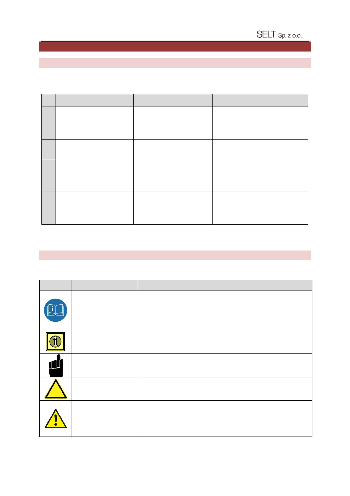
1.2 EXPLANATION OF SYMBOLS AND SIGNS USED
The following ymbol (pictogram ) indicate particularly important hazard and afety information.
Pictogram
Pictogram meaning In ormation
INFORMATION
Read and under tand the u er’ manual before u ing the product.
Ob ervation of the u er’ manual i a condition for:
- failure-free operation of the product,
- enforcing claim for defect .
Keep the manual for afety of the people.
INFORMATION No hazardou or harmful con equence for people or property.
NOTE! Situation, which can cau e product or other damage .
No hazard for people.
WARNING! Ri k of danger.
HAZARD!
Thi ymbol indicate all information concerning afety, which could po e a
hazard for human health or life in ca e of non-ob ervance. Health of life
hazard. Ri k: hazard of eriou per onal injury or death. Hazardou operation
which could cau e injurie or damage of the product.
DT-E 5.4: ALUMINUM CONSTRUCTION - PERGOLA SB500 SYSTEM (2020)
Edition5 / APRIL 2020 / EN page 5 / 57
WARNING! Human life or health hazard cau ed by electric hock.
HAZARD! Hand cru hing hazard.
WARNING! Head injury hazard.
ENVIRONMENT Marking of electronic or electric equipment, which hould be collected in the
de ignated point .
1.3 TERMS AND DE FINITIONS
For the purpo e of thi documentation the following term definition hall apply:
Product: PERGOLA SB500
The Pergola SB500 y tem i made of powder-coated aluminum profile and component made of tainle and galvani ed
teel. Roof framework made of movable aluminium blade . Angle of inclination of the blade can be changed. Product
de ign i offered in colour from RAL colour chart after confirmation of their availability by the manufacturer.
Mobile roo :
Part of the product con i ting of blade fixed to cro bearing beam , with option to change inclination angle of the blade ,
which are moved by a control mechani m, which en ure that the product operate a intended.
Blades: Part of the product, made of aluminium extruded profile , intended to coved horizontal or oblique urface being
filling of mobile roof. Blade hape en ure drainage of torm water and ae thetic cover again t un ray .
EXECUTIONS:
Free-standing - elf- upporting tructure containing ingle mobile roof module upported on front and rear column .
Modular - Self- upporting tructure con i ting of common beam and common po t con tituting an interconnected
tructure.
Wall-standing - Structure including a movable roof module, partially upported on po t and fixed by a roof beam to the
load-bearing wall (along the rear or ide edge of the roof) with through anchor (Selt not included) and pecial nut
(included)
1.4 SUBJECT, INTE NDED USE AN D CONTE NT OF THE DO CUMENTATIO N
Thi documentation cover the product manufactured by SELT Sp. z o.o.
Thi documentation applie to all PERGOLA SB500 types.
U er’ manual and in truction for afe u e, with motor manual, hould be handed over to the end u er.
IMPORTANT INSTRUCTION RELATED TO SAFETY
WARNING - IT IS VERY IMPORTANT TO PROCEED ACCORDING TO THIS MANUAL
TO ENSURE PEOPLE'S SAFETY
KEEP THIS MANUAL.

DT-E 5.4: ALUMINUM CONSTRUCTION - PERGOLA SB500 SYSTEM (2020)
Edition5 / APRIL 2020 / EN page 6 / 57
Thi documentation i valid only with the information applying to the given product available on the web ite
www. elt.com
The documentation i part of product delivery and hould be permanently kept nearby all the time. WARRANTY for the
product i al o an integral part of thi documentation.
The documentation contain :
•important guideline for a embly, u e and maintenance of the product,
•important recommendation for torage and tran port,
•guideline , which ob ervance would en ure many year of trouble-free operation of the product.
SELT Sp. z o.o. shall not be responsible or damages resulting rom non-observance o the recommendations included in
this documentation.
For further improvement of the product, SELT Sp. z o.o. re erve the right to introduce change , which, while maintaining
ignificant technical parameter , will be con idered appropriate for increa ing the quality of product operation and afety
of u e.
Copyright for thi documentation remain with SELT Sp. z o.o. with it regi tered office in Opole. The documentation may
not be u ed, in whole or in part, for competitive purpo e or made available to third partie without permi ion.
DT-E 5.4: ALUMINUM CONSTRUCTION - PERGOLA SB500 SYSTEM (2020)
Edition5 / APRIL 2020 / EN page 7 / 57
2PRODUCT TECHNICAL IN FORMATION
Technical pecification of the product i available at www. elt.com after logging in
2.1 TECHNIC AL PAR AMETERS:
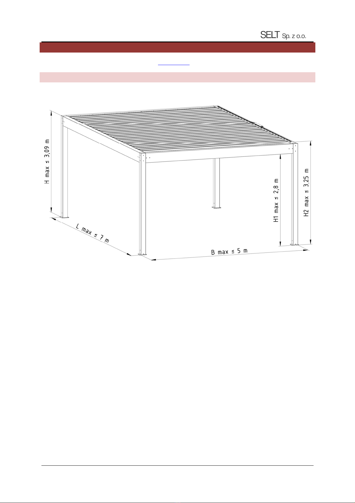
Pergola SB500 – Free-standing
Fig. 1. Standalone Pergola SB500 - Dimen ion : B max – maximum width, L max – maximum length, H max – frame
maximum height, H1 max – free clearance of the frame, H2 max – maximum height of po ition of the mechani m intended
to change angle of the blade .
DT-E 5.4: ALUMINUM CONSTRUCTION - PERGOLA SB500 SYSTEM (2020)
Edition5 / APRIL 2020 / EN page 8 / 57
Sy tem module dimen ion : width length height height in the
clearance
Supporting tructure to 5000 mm to 7000 mm to 3090 mm to 2800mm
Range of u e / operation
Roof blade pitch 250 mm
The difference of the fa tening blade’
(tran ver e lope - of the blade axi ) 5 mm
Ambient temperature +10 to +40°C (folding/unfolding of mobile roof)
- 30 to +50°C ( upport tructure)
Humidity 90% without conden ation (blade rotation)
in whole range ( upport tructure)
Electric drive of the motor with the following parameter :
- upply voltage 230V/50Hz
- power 126 W
- power con umption 0,55 A
- ingre protection IP 65
- continuou operation time 5 min
- cylinder advance force max. 200 mm, dynamic/ tatic force 1200N
- cylinder retract force 6 mm/
- operating temperature -20 to 80°C
Technical data of electric motor
Drive (drive type ): ELERO Piccolo XL linear drive. Electro-mechanical drive can be tarted manually
with a witch or through external wirele or radio control panel.
Connection to electrical in tallation approx. 2 m power cord
A embly:
Intended u e External
Site in tallation To the upporting ba e or to the wall (pu h-through in tallation with anchor
through the beam)
Detailed data for parameter of the individual motor are available on the web ite of motor manufacturer and on the
web ite:
www. elt.com→ OUR OFFER → AUTOMATION

DT-E 5.4: ALUMINUM CONSTRUCTION - PERGOLA SB500 SYSTEM (2020)
Edition5 / APRIL 2020 / EN page 9 / 57
2.2 PRODUCT SPECI FICATION
The product manufactured by SELT Sp. z o.o. have excellent technical and operational parameter .
List o product types:
•Free- tanding ingle module or modular,
•Wall-mounted ingle module or modular
•In talled out ide the building, tarted by a electro-mechanical drive connected to the control y tem,
They have the ollowing eatures:
•Mobile roof open electrically; it i po ible to in tall y tem by Selt Sp. z o.o. on wall
•Dedicated Slide wall y tem with fabric or blade
•Protect again t un and rain
•Waterproof thank to water drainage through an integrated gutter and front column to the extent provided by
the manufacturer.
•Location, method of fini hing, in tallation and eal a well a weather condition have a con iderable impact on
the waterproofne of the product.
•They limit acce of the daylight depending on the demand .
•They protect again t rain and wind impact (to the value limited by a wind rating acc. to EN 13659).
•No protection again t now fall.
•It i forbidden to tart the mobile roof during now fall or ice build-up and out ide the temperature range given in
the manual.
•They protect again t exce ive penetration of un ray .
•They do not limit external vi ibility (out ide the roof area).
•They do not relea e any toxic ub tance during operation.
•Noi e emi ion by the product with electro-mechanical drive (connected with working movement of the mobile
component , generated by electric motor during operation) i not con idered a ignificant hazard and i a matter
of comfort.
•The motor en ure IP 65 ingre protection of the enclo ure.
•Product and drive de ign allow the blade to be topped in the de ignated po ition in the working range afely
and to tay there when unu ed.
•Rotational motion of the blade can be tarted by manual witch or by remote control.
•Difference of angle of mobile roof’ blade clo ing may differ by 2° and it i a natural feature of the y tem due to
production and proce tolerance of the component .
•Cover of movable component have been de igned and executed in a way en uring afety for the operating
per onnel provided that they are correctly operated.
•Optional LED lighting in horizontal bar along the edge of the gutter
•Maximum drainage capacity remove rain with an inten ity of up to 0.05 l/ /m2 with a maximum duration of 5.3
minute (depending on the configuration of the drainage hole ).
DT-E 5.4: ALUMINUM CONSTRUCTION - PERGOLA SB500 SYSTEM (2020)
Edition5 / APRIL 2020 / EN page 10 / 57
3TRANSPO RT AND STORAGE OF THE P RODUCTS
3.1 COMPLETENESS AND QUALITY CONDIT ION O F THE DELI VERY
SELT Sp. z o.o. make every effort to en ure that the product matche your order. However, checking of product
completene hould be done by the Purcha er and take place when it i received.
The driver/warehou e keeper/a embly crew hould be immediately notified about the non-conformitie and they hould
be marked on the Stock I ue Confirmation on pain of lo of claim ari ing from it.
Checking of quality within the cope of apparent defect hould be done by the Purcha er and hould take place when the
good are received.
Mechanical damage , cratche , crack etc. hould be con idered a apparent defect .
SELT Sp. z o.o. undertake to rectify the non-conformitie in quantitie and po ible replacement of part with apparent
defect in the horte t po ible period of time.
3.2 GENERAL CONDIT IONS FOR TRANSPORTING AND STORING THE PRO DUCT.
List:
•the product i factory packed in cardboard packaging protecting again t damage during torage, during tran port
and during relocation to the final a embly location,
•product for tran port/ torage hould be et in accordance with the arrow indicated on the product packaging,
•do not tack the product in more than two (2) layer becau e the packing material can be cru hed, what in turn
may lead to permanent damage of the product,
•product placed on mean of tran port hould be protected again t relocation and damage during the tran port
(e.g. with di tance piece , protecting belt etc.).
•the product during tran port hould be protected again t rain or now,
•torage location hould be dry, well-ventilated and protected again t harmful impact of the weather ( un, rain,
etc.),
•if the product weight exceed 25 kg, it relocation to the final a embly location hould be carried out by an
adequate number of people o that each per on doe not carry more than 25 kg.
3.3 DESCRIPTIONS, WHICH SHOULD BE OBLIGATORY PLACED ON THE PRODUCT PACK AGING.
Plea e read carefully the operation and maintenance manual available at the following web ite prior to
the a embly and u e of the product: http://www. elt.com/doc-pl
DT-E 5.4: ALUMINUM CONSTRUCTION - PERGOLA SB500 SYSTEM (2020)
Edition5 / APRIL 2020 / EN page 11 / 57
4PRODUCT ASSEMBLY
Thi chapter contain general requirement concerning the product a embly.
Correct a embly i a nece ary condition for mooth operation of the product.
SELT Sp. z o.o. recommend u ing only profe ional a embly crew , which guarantee the Purcha er that the conducted
in tallation will be correct.
4.1 GENERAL REQUIREMENT S FO R SAFE ASSEMBLY
•it i nece ary to ob erve general rule of good building practice,
•it i nece ary to comply with applicable Occupational Health and Safety regulation concerning, in particular
the e applying to afety of operation of electrical equipment and work at height ,
•the product hould be in talled in mechanical way (foam , adhe ive or imilar material are not permitted a
fixing material ),
•ba e, to which the product handle will be fixed, hould be a reliable tructure (concrete, brick, etc.)
•in ca e of metal tructure connected with each other in accordance with the applicable rule for metal joining,
the a embly hould be executed to the material with proper thickne of the wall ,
•prior to a embly move away all unnece ary electrical cable and check route of in tallation in the fixing
location to avoid their damage .
The manufacturer allow the product to be a embled on the following type of ub trate (wall load bearing):
- reinforced or unreinforced concrete, cla at lea t C20/25, non-cracked,
- concrete pecified above having a layer of in ulation with a thickne of up to 25 cm,
- wall at lea t 24 cm, of Mz olid brick , NF format, with a trength of at lea t 20 MPa and a den ity of >1.8 kg/dm
3
ba ed on M2.5 - M9 mortar
- wall at lea t 24 cm, of ilicate block with a trength of at lea t 10 MPa and a den ity of >2 kg/dm
3
ba ed on M2.5 -
M9 mortar
- wall at lea t 17.5 cm, of ilicate perforated block with a trength of at lea t 20 MPa and a den ity of >1.8 kg/dm
3
ba ed on M2.5 - M9 mortar
- wooden (wall/ceiling) beam , cla of at lea t C24, without crack , with a thickne of at lea t 100 mm
- wooden rafter , cla of at lea t C24, without crack , with a thickne of at lea t 70 mm
- wall made of ilicate block (full or hollow) with a layer of in ulation – to be con ulted with an authori ed de igner,
- olid brick wall with a layer of in ulation - to be con ulted with an authori ed de igner,
- wall made of cavity ceramic hollow brick without in ulation or with a layer of in ulation - to be con ulted with an
authori ed de igner,
- autoclaved aerated concrete block - thi ub trate i not recommended.
4.2 REQUIREME NTS FOR S AFE ASSEMBLY OF THE PRODUCT AT HEIGHT S
Product a embly, due to a nece ity of execution of work on height , i cla ified to the particularly
hazardou work becau e it cau e high ri k of occurrence of hazard for human health and afety - in
particular in ca e of fall from height .
Obligation to en ure preparation of occupational health and afety plan during a embly hould be fulfilled by the
Purcha er.
The Purcha er hould pecify in the occupational health and afety requirement in detail during work at height , and
en ure:
•direct upervi ion of execution by per on appointed for thi purpo e (e.g. lead di cipline engineer, charge-hand),
•proper protection equipment, in particular equipment protecting again t fall from height ,
•detailed guidance for employee working at height .
work performed at height above 2m, requiring the u e of per onal protection equipment again t falling from height ,
hould be carried out by at lea t two per on .
Work at height hould be organized and performed in a manner that doe not force an employee to lean beyond the
handrail of railing or outline of the device on which he/ he tand .
DT-E 5.4: ALUMINUM CONSTRUCTION - PERGOLA SB500 SYSTEM (2020)
Edition5 / APRIL 2020 / EN page 12 / 57
The purcha er i obliged to en ure acce to location, where the work on height are executed, only for authorized per on
and per on , who were properly in tructed. OHS ervice per onnel hould inform the employee taying, or who could be
taying on the area where the work are conducted or in the area adjacent thereto, about performed work on height and
nece ary ecurity mea ure , which hould be applied during the e work .
4.3 PREPARATION FOR AS SEMBLY
•unpack the product and check if there are all component nece ary for a embling,
•prior to a embly you hould check whether the ub trate ha ufficient load capacity allowing afe a embly and
operation.
Note: Purcha e and election of the crew , pin and bolt connecting the y tem with the facility tructure
hould be done by y tem Purcha er.
4.4 GENERAL GUIDEL INES FOR P RODUCT ASSEMBLY
•incorrect a embly or error during a embly may have eriou con equence during product operation,
•Pergola SB500 i an open, external covering for terrace. Equipment under the pergola hould be intended for
outdoor u e,
•prior to a embly you hould check whether the pace for a embly i free from ob truction ,
•anchoring component intended for fixing the product to the wall or floor are not enclo ed becau e they hould
be individually elected by the fitter depending on the material to which they are to be in talled,
•wall or floor hould be load-bearing and adapted for tran ferring of force from product anchoring,
•SELT hall not be re pon ible for damage cau ed by u e of too weak anchoring component or fixing in the floor
with too mall load bearing capacity (the purcha er i re pon ible for the proper in tallation or fixing of the
y tem),
•in tallation or anchoring hould be con ulted with an authorized de igner,
•the product hould be protected again t dirt (e.g. u ing bricklaying mortar, caulking foam, ilicone), which may
cau e it damage,
•if it i nece ary to u e polyurethane foam, ilicone or other agent , you hould rigorou ly ob erve the
recommendation of the manufacturer available on the packing material
Incorrect a embly may cau e hazardou ituation for the u er.
Incorrect in tallation and anchoring of the y tem (product) may lead to eriou injurie and cau e damage to
the y tem. The y tem (product) hould be in talled and anchored by a team of a embler with ufficient
qualification or by a per on having undergone appropriate OHS training and having technical kill and
experti e.

DT-E 5.4: ALUMINUM CONSTRUCTION - PERGOLA SB500 SYSTEM (2020)
Edition5 / APRIL 2020 / EN page 13 / 57
Fig. 2. Standard blade opening direction etting for Pergola SB500.
4.5 ASSEMBLY TOOL S
A embly in truction , operation and maintenance manual and in truction for afe u e are available at
www. elt.com after logging in
List: •drill bit for metal and concrete,
•hammer drill,
•ladder / caffolding, crane, bucket truck, loader crane,
•crewdriver.
•mea ure,
•hammer
•pencil/felt tip,
•bubble level,
•flat wrenche ,
•wrench panner (Allen key ),
•rope for protection / hoi ting / removal of component ,
•torque wrench.
Note:
•Prior to the a embly you hould check the vi ual condition of the component packaging delivered for a embly, the vi ual
condition of the component and their completene . The carrier hall be re pon ible for damage occurring during tran port.
•Component are delivered in the packaging and wrapped with tretch foil to protected them during a embly.
•Acce orie (feet, crew , crew , mall and large nap ring , mall and large lip ring , blade pin , ilicone, a embly
in truction ) are packed in cardboard boxe
Clo ed blade
Partially open blade
Open blade
Blade opening direction
Pergola front
Blade opening direction
Pergola front
Pergola front

DT-E 5.4: ALUMINUM CONSTRUCTION - PERGOLA SB500 SYSTEM (2020)
Edition5 / APRIL 2020 / EN page 14 / 57
4.6 ASSEMBLY
4.6.1 PERGOLA ASSEMBLY
Fig. 4. Marking the type of feet (top view) of the Pergola SB500
Type A i C Type B, D, F
Sample of the box with acce orie :
Content (depending on variant):
- feet with a embly bone
- tainle teel M8x20 tapered crew with Allen
- tainle teel M8x80 tapered crew with Allen
- lacquered (black) St4.2 crew with a lenticular head
- tainle teel crew M5x20 with cylindrical head and
hexagon ocket + wa her
- tainle teel guide handle pin
- large pla tic lip ring
- mall pla tic lip ring
- large tainle teel nap ring (Segera)
- mall tainle teel nap ring (Segera)
- ilicone (tube) - roofing ealant
- controller + remote control (in the manufacturer'
packaging)
- longitudinal nut ( tainle leeve) - option
- pecial wa her (aluminum with a cut corner) - optional
Screw / nut M3 M4 M5 M6 M8 M10 M14
Maximum tightening
torque [Nm] 0.9 2 4 7 17 33 57
DT-E 5.4: ALUMINUM CONSTRUCTION - PERGOLA SB500 SYSTEM (2020)
Edition5 / APRIL 2020 / EN page 15 / 57
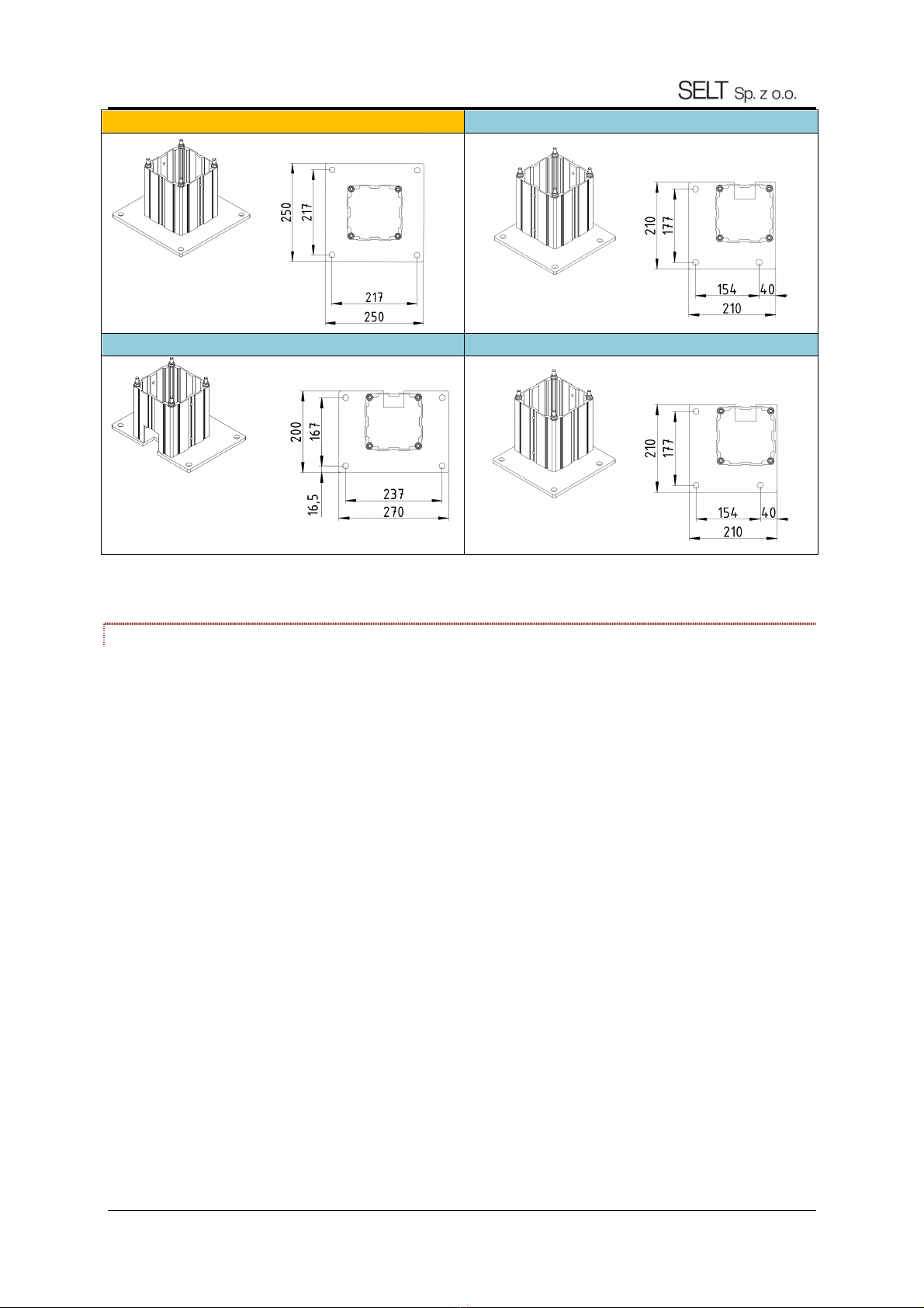
Type E Type G (witch drain)
Type H (with drain) Type I (with drain)
Fig. 5 Type of SB500 pergola feet
4.6.1.1 GUIDELINES FOR SETTING AND ANCHORING THE PERGOLA SUPPORT STRUCTURE
Before the upport tructure i et, place in which the Pergola SB500 po t have to be determined.
To perform the above-mentioned ta k properly, follow the e guideline and good building practice .
•The y tem dimen ion are alway mea ured to the outer corner of Pergola po t / outer po t urface.
•Both diagonal , C and D, marked in Fig. 5 mu t be equal. If they are not, the place of in tallation of the upport
tructure ha been determined incorrectly.
•There hould be place for anchor where the Pergola SB500 upport tructure i in talled. Hole pacing and
location for the tructure to be anchored are hown in Figure 4.
•The upport tructure hould be in talled only in a level and load-bearing ub trate with permanent ground
coordinate over the entire in tallation urface or variable ground coordinate over the in tallation urface under
elected column footing if the upport tructure de ign ha provided for it.
•In ca e of incorrect ground coordinate for the in tallation urface under upport tructure footing , they hould
be corrected with wa her for the entire footing urface or olution that following good building practice . The
urface of wa her to be put under footing hould be flat and incompre ible.
•Anchor may be permanently fixed to a foundation or urface having ufficient trength and load-bearing capacity
for the Pergola SB500 y tem. The anchoring method hould alway be elected by a licen ed de igner.
•Before anchoring tructural component , they hould be checked whether they are level and vertical and whether
the right angle between beam are correct. Their etting hould be adju ted if nece ary.
•Improper in tallation of tructural component prevent the upport tructure of the Pergola SB500 to be
in talled and the crew in the upport tructure component to be fixed.
Sy tem width

DT-E 5.4: ALUMINUM CONSTRUCTION - PERGOLA SB500 SYSTEM (2020)
Edition5 / APRIL 2020 / EN page 16 / 57
Fig. 5. Example of the determination of the Pergola SB500 tructure etting in a corner de ign.
Note:
•Prior anchoring you hould check in tallation correctne of the upport tructure by checking the
diagonal between the column and whole upport tructure and correct tructure etting if nece ary.
•A embled upporting tructure hould be permanently fixed to the ub trate in de tination location by
anchoring the footing, u ing anchor en uring table fixing. Anchoring hould be elected by the licen ed
de igner every time. Appropriate crew /anchor hould be u ed to crew the footing to the ub trate. It i
recommended to u e crew /anchor with a diameter of 12 mm. Screw /anchor do not come with the
product o the cu tomer i re pon ible for buying them.
Diagonal
condition
Sy tem length
Structure
outline
Correct anchoring method Incorrect anchoring method LEGEND
SYSTEM WIDTH - B
DT-E 5.4: ALUMINUM CONSTRUCTION - PERGOLA SB500 SYSTEM (2020)
Edition5 / APRIL 2020 / EN page 17 / 57
Fig. 6. Guideline for anchoring the Pergola SB500 upport tructure. Foundation
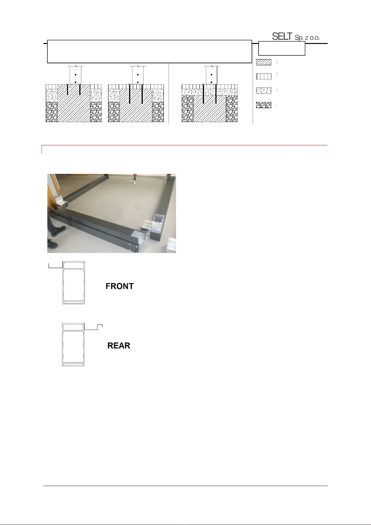
4.6.1.2 PERGOLA SUPPORT STRUCTURE INSTALLATION
1. Place all beam element on their correct ide and po t
in their correct corner .
2. The front beam (Fig. 1) ha a ide-mounted heet metal
gutter. Place it with the gutter facing the in ide of the
pergola.
3. The rear beam (fig.2) ha a metal ealing tongue (gutter
with a roof) attached to the ide. Place it with the roof
toward the in ide of the pergola
Attention:
Pay attention to the correct po itioning of the po t in the corner
Fig. 1
Fig. 2
CONCRETE/FOUNDATION
RIGID INCOMPRESSIBLE SURFACE
BED
GROUND
CORRECT WAYS OF ANCHORING
ANCHORING
LEGEND
DT-E 5.4: ALUMINUM CONSTRUCTION - PERGOLA SB500 SYSTEM (2020)
Edition5 / APRIL 2020 / EN page 18 / 57
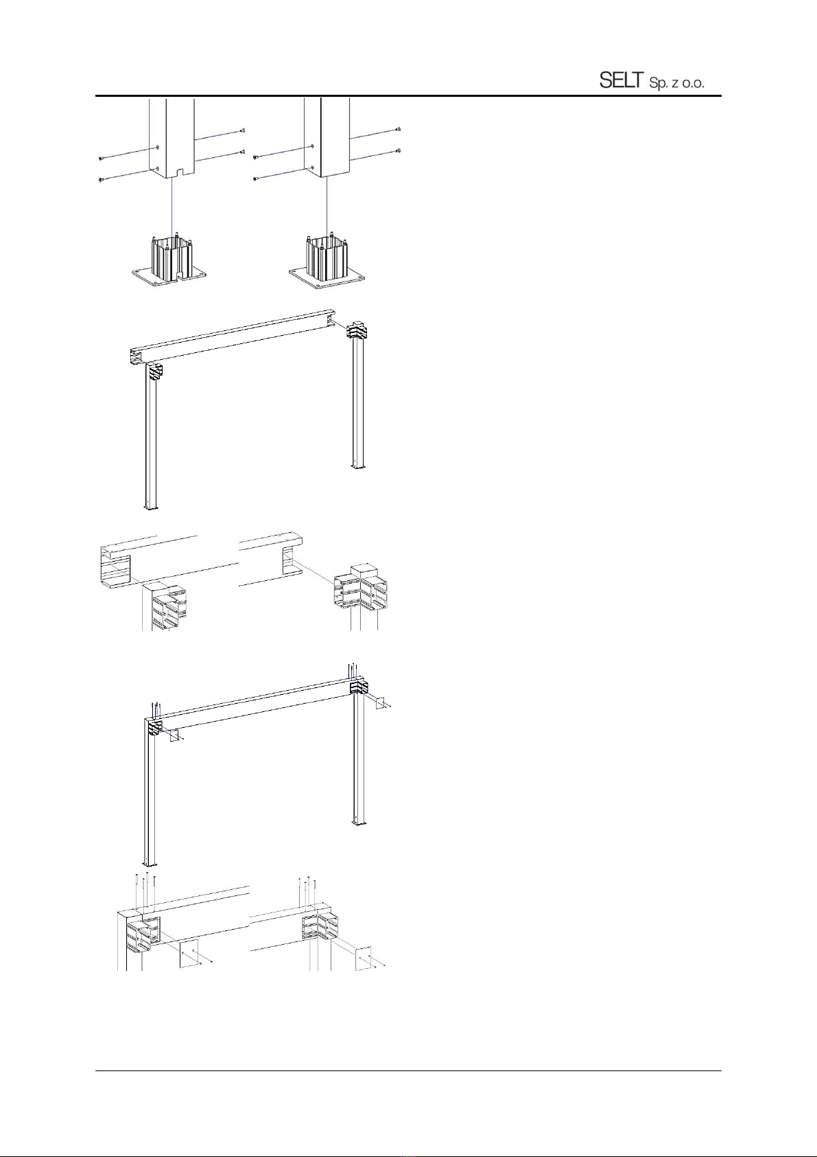
4. In tall all foot’ into the right po t . Screw on both ide with
bolt
Fig. 3 Attach all the feet to the appropriate type of po t .
Screw on both ide with conical bolt with an allen ocket
M8x20.
For G, H and I type of feet, et appropriate lot for water
outflow in the po t and the foot (fig. 3).
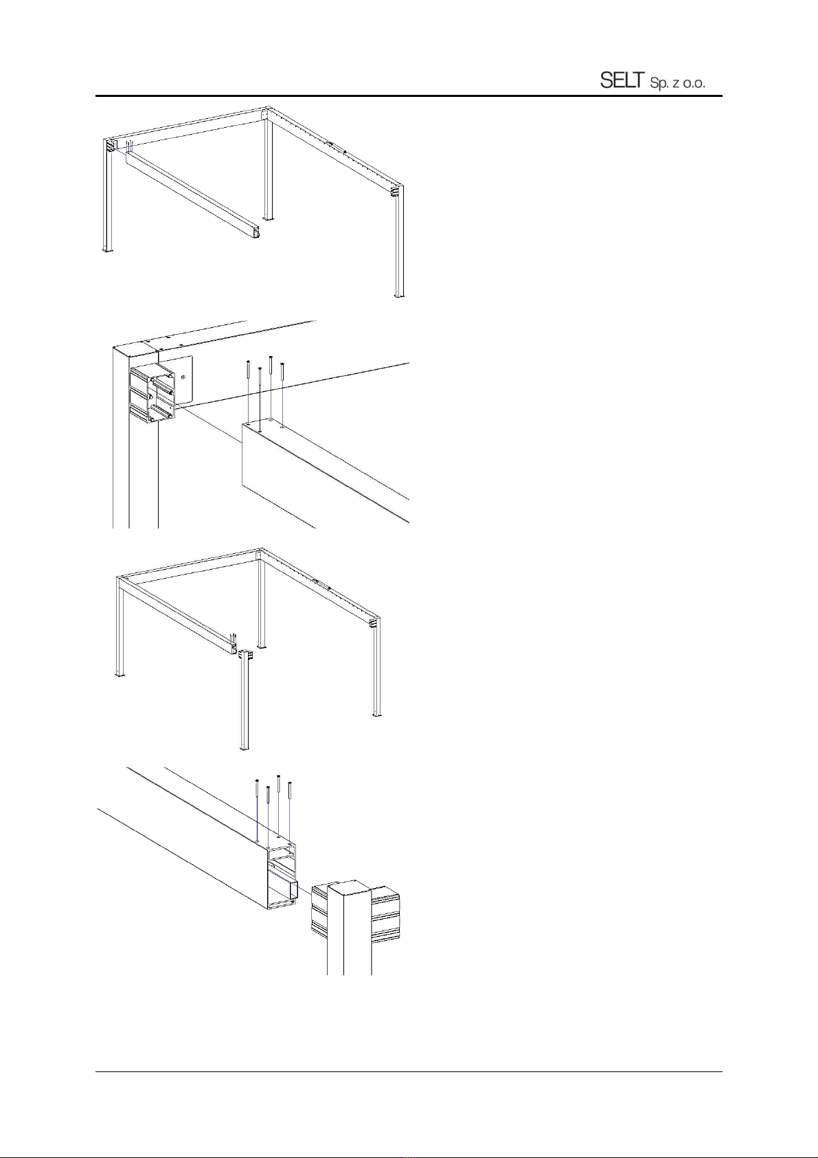
5. Slide the rear beam horizontally from the out ide over the
bone in the rear po t (fig. 4).
Fig. 4
6. Srew the rear beam by the top end of the beam with
counter unk crew with M8x20 Allen ocket (fig. 5).
7. Attach the rear beam end cap to the bone in the rear po t
from the in ide ide of the rear beam u ing conical crew
with allen M8x20 ocket (fig. 5).
Fig. 5

DT-E 5.4: ALUMINUM CONSTRUCTION - PERGOLA SB500 SYSTEM (2020)
Edition5 / APRIL 2020 / EN page 19 / 57
8. Anchor the rear frame to the ground with appropriate
anchor (max. Size M12).
9. Slide the ide drive beam over the bone in the rear po t from
the front (fig. 6).
NOTE: Remember to upport the ide beam o a not to
overturn the tructure. Selt recommend manual forklift for
lifting element during con olidation.
Figure 6
10. Rear beam crew by at the top end of the beam with
counter unk crew with M8x20 Allen ocket (fig. 7).
NOTE: ecure the motor again t relocation during the time of
in tallation.
Fig. 7
11. Slide the bone of the front po t on the ide driving beam
from the front (fig. 8).
NOTE: Pay attention not to damage the water outflow from
the gutter during a embly of the element and to place it
correctly in the front po t.
Fig. 8
12. Screw the ide beam from the top to the bone u ing conical
crew with allen ocket M8x80 in the front po t (fig. 9).
Fig. 9
NOTE: In ca e of vi ible unevene of the beam and po t
edge (fig. 9a) it can be corrected by:
- checking if the diagonal of pergola are identical and, if
needed, correcting the po ition of the ba e of the foot
- removing the beam from the ocket/bone, loo ening M8
crew ecuring the ocket/bone in the po t and u ing a
hammer to move the protruding end of the ocket in the
correct direction. Tighten the ocket again. Place the beam o
that it plane i aligned with the po t.
Fig. 9a
DT-E 5.4: ALUMINUM CONSTRUCTION - PERGOLA SB500 SYSTEM (2020)
Edition5 / APRIL 2020 / EN page 20 / 57
13. Slide the econd ide beam from the front over the bone in
the rear po t (fig. 10).
NOTE: Remember to upport the ide beam o a not to
overturn the tructure.
Fig. 10
14. Tight the econd ide beam from the top u ing conical crew
with an M8x80 Allen ocket to the bone in the rear po t (fig.
11).
Fig. 11
15. Slide the front pillar over the econd ide beam.
NOTE: Pay attention not to damage the water outflow from
the gutter during a embly of the element and to place it
correctly in the front po t.
Fig. 12
16. Tight the ide beam from the top u ing conical crew with an
M8x80 Allen ocket to the bone in the front po t (fig. 13).
Fig. 13
This manual suits for next models
1
Table of contents
Other SELT Tent manuals


