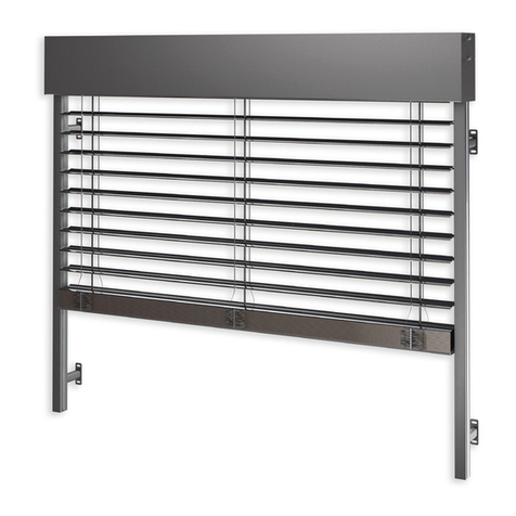
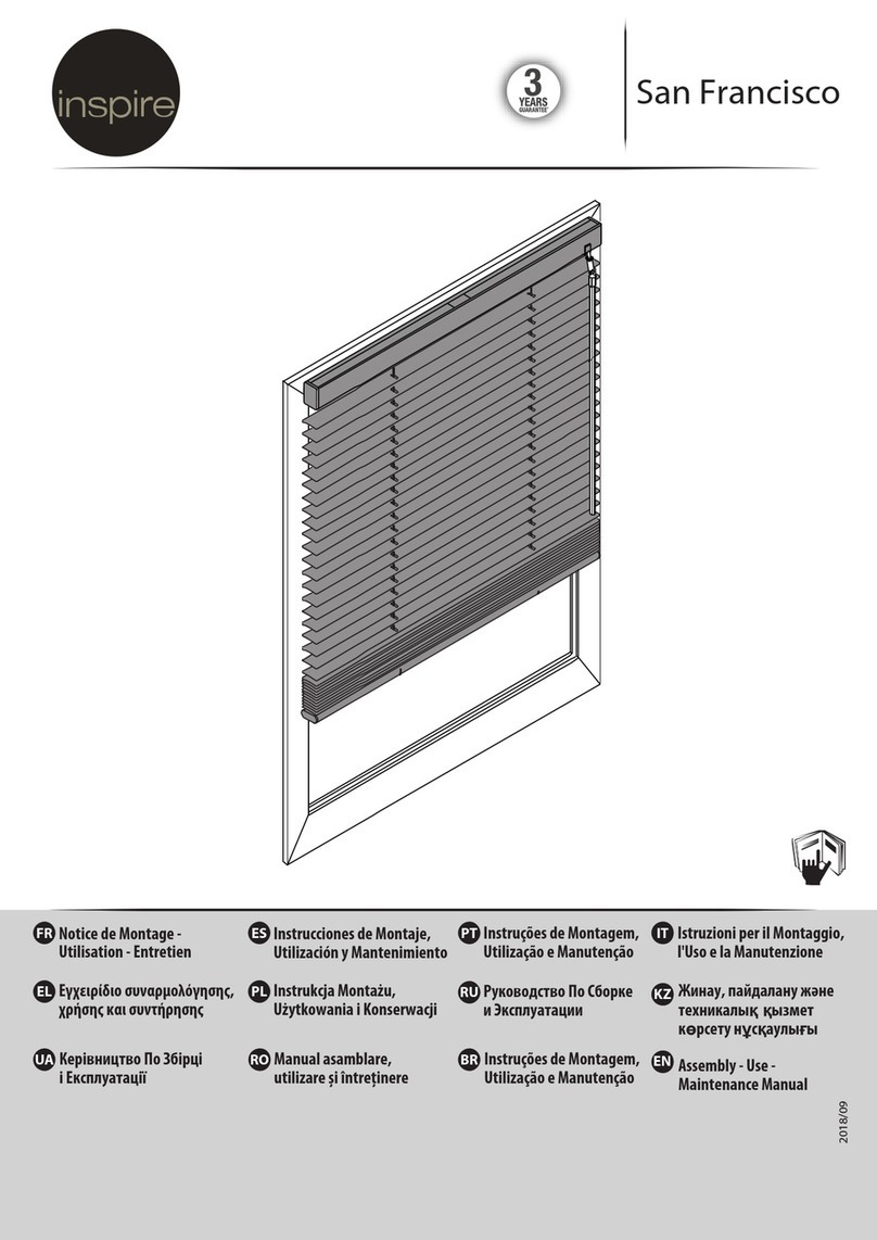
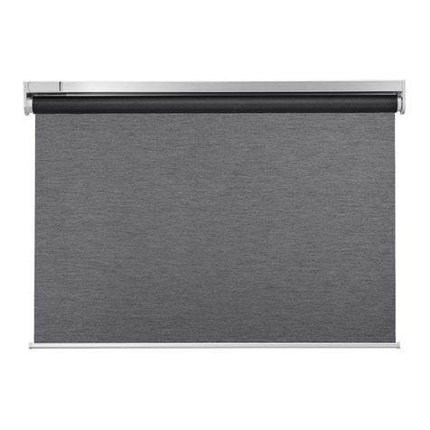
SELT Venetian Blind Z90 User manual

TECHNICAL AND OPERATIONAL DOCUMENTATION
INSTALLATION AND OPERATING MANUAL
AND INSTRUCTIONS FOR SAFE USE
1. Sun protection screen Venetian Blind
1.4. Venetian Blind Z90
1.3
DT-E

DT-E 1.4: SUN PROTECTION SCREEN –VENETIAN BLINDS Z90
Issue 5 / June 2019 / EN page 2 / 44
PRODUCT NAME:
SUN PROTECTION SCREEN
VENETIAN BLIND Z90
PRODUCT MANUFACTURER’S MARKING:
Manufacturer’s name:
SELT Sp. z o. o.
Manufacturer’s head office:
45- 449 Opole, ul. Wschodnia 23A
Contact details:
Tel: +48 77 553 21 00 (sekretariat)
Fax: +48 77 553 22 00
Website
www.selt.com
E-mail:
PRODUCT SAFETY MARKING:
Product conforms to CE safety requirements.
THIS TECHNICAL AND OPERATIONAL DOCUMENTATION:
Is valid from: 15 June 2019
Is valid for product versions designated above.

DT-E 1.4: SUN PROTECTION SCREEN –VENETIAN BLINDS Z90
Issue 5 / June 2019 / EN page 3 / 44
SPIS TREŚCI
1. INTRODUCTION............................................................................................................................................................ 4
1.1. Product safety tips .................................................................................................................................................. 4
1.2. NOTES ON SYMBOLS AND MARKS .......................................................................................................................... 4
1.3. DEFINITIONS............................................................................................................................................................ 5
1.4. SUBJECT, DESIGNATION AND CONTENS OF THE DOCUMENTATION ...................................................................... 5
2. PRODUCT TECHNICAL INFORMATION.......................................................................................................................... 6
2.1. TECHNICAL PARAMETERS: ...................................................................................................................................... 6
2.2. PRODUCT CHARACTERISTICS .................................................................................................................................. 6
3. PRODUCT Transport AND STORAGE ............................................................................................................................ 7
3.1. COMPLETNESS AND QUALITATIVE STATE OF DELIVERY.......................................................................................... 7
3.2. GENERAL CONDITIONS OF PRODUCT transport AND STORAGE ............................................................................. 7
3.3. DESCRIPTIONS THAT HAVE TO BE PUT OBLIGATORY ON THE PRODUCT PACKAGING............................................ 7
4. PRODUCT INSTALLATION............................................................................................................................................. 8
4.1. REQUIREMENTS FOR SAFE INSTALLATION AT HEIGHTS.......................................................................................... 8
4.2. PrEPARATION TO INSTALLATION ............................................................................................................................ 9
4.3. GENERAL GUIDELINES FOR INSTALLATION ............................................................................................................. 9
4.4. INSTALLATION TOOLS ............................................................................................................................................. 9
4.5. INSTALLation........................................................................................................................................................... 9
4.5.1. Installation of the venetian blind Z90 with cover panel..................................................................................... 9
4.5.2. installation of venetian blind Z90 –cable guide............................................................................................... 13
4.5.3. installation of venetian blind Z90 MIX (WITH GUIDE AND CABLE RAIL)........................................................... 15
4.5.4. Installation of Venetian blind Z90 with cube and oval guide rails (self-supporting product)........................... 16
4.5.5. installation of venetian blind Z90 with cube and oval guide rail –group installation...................................... 18
4.5.6. Manual drive .................................................................................................................................................... 22
4.5.7. Concealed guide rail installation ...................................................................................................................... 23
4.5.8. WINDOW FRAME GUIDE RAIL INSTALLATION.................................................................................................. 26
4.5.9. Z90 BOX WITH UNDER-PLASTER CASSETTE INSTALLATION................................................................................ 28
4.5.10. INSTALLATION OF VENETIAN BLINDS Z90 BOX WITH UNDER - PLASTER CASSETTE BOX3, BOX4, BOX5.......... 34
4.6. ELECTRIC DRIVE..................................................................................................................................................... 35
4.6.1. Connection to power supply ............................................................................................................................ 35
4.6.2. Start-up and adjustment .................................................................................................................................. 36
4.6.3. Manual drive .................................................................................................................................................... 36
5. System operation and product safety........................................................................................................................ 36
5.1. General safety requirements ................................................................................................................................ 36
5.2. Safety requirements connected with particular conditions and places of product use ....................................... 37
5.3. Operation safety ................................................................................................................................................... 37
5.4. Supervision of safe product use............................................................................................................................ 38
6. System use and maintenance .................................................................................................................................... 39
6.1. Using the product in accordance with its intended use........................................................................................ 39
6.2. Instructions for non-professionals........................................................................................................................ 39
6.3. Technical inspections, maintenance and repairs .................................................................................................. 39
7. General warranty conditions ..................................................................................................................................... 40
7.1. Exclusions for warranty......................................................................................................................................... 40
8. Complaints/ technical faults ...................................................................................................................................... 41
8.1. Complaints............................................................................................................................................................ 41
8.2. Technical faultS..................................................................................................................................................... 42
9. Product disassembly / utilisation / disposal .............................................................................................................. 42
10. Marking and labelling the product with the CE mark ................................................................................................ 43
10.1. Product compliance with the CE standard............................................................................................................ 43
10.2. Information accompanying the CE marking.......................................................................................................... 43

DT-E 1.4: SUN PROTECTION SCREEN –VENETIAN BLINDS Z90
Issue 5 / June 2019 / EN page 4 / 44
1. INTRODUCTION
1.1. PRODUCT SAFETY TIPS
The product was manufactured in accordance with the latest know-how in the area of constructing and manufacturing and
is delivered in condition allowing for its safe use..
Safe construction of the product is achieved by:
No.
Subject
European legal basis
Polish legal basis
1
Shutters and external
venetian blinds-Performace
requirements including
safety
EN 13659:2015
PN-EN 13659:2015
2
Construction products (CPR)
Regulation 305/2011 of the
European Parliament and the Council
DZ. U [Journal of Laws] 2004, No. 92,
item 881 as amended by, DZ. U
[Journal of Laws] 2016, No. 1570;
2015, No. 1165; 2016, No. 542
3
Essential requirements for
machines
Directive 2006/42/EC of the European
Parliament and the Council
Resolution of the Minister of
Economy of 21 October 2008
DZ.U. [Journal of Laws] 2008 no. 199,
item 1228 as amended DZ.U.
[Journal of Laws] 2011.124
Linked documents: Declaration of performance (external products), Declaration of conformity (product with motor) and
manual of installation and use of motors and control.
1.2. NOTES ON SYMBOLS AND MARKS
The below symbols (icons) denote particularly important information concerning threats and safety.
Icon
Icon meaning
Information
INFORMATION
Prior to using the product, its operating manual should be read.
Following the operating manual guarantees:
- failure-free use of the product,
- warranty coverage against product defects.
Keep the operating manual for safety of people.
INFORMATION
No harmful or dangerous consequences for people or facilities.
ATTENTION!
A situation likely to cause product damage or other damage.
No threat for people.
WARNING!
Threat of danger
DANGER!
This symbol denotes all information concerning danger, failure to observe
which brings about threat to human life and health. Risk: threat of serious injury
or death. Dangerous operation which may cause injuries or product damage.
WARNING!
Threat to human life or health due to electric shock.
ENVIRONMENT
Marking on electric or electronic equipment subject to collection in designated
places.

DT-E 1.4: SUN PROTECTION SCREEN –VENETIAN BLINDS Z90
Issue 5 / June 2019 / EN page 5 / 44
1.3. DEFINITIONS
The following terms and definitions used within this documentation shall mean:
Product: Venetian Blind Z90
VENETIAN BLIND: The external sun protection system, installed outside the building, over or inside the window opening
building in which lifting and dropping of the aluminum slats is made by the operating mechanism (manual with hand crank,
electric with drive connected to the steering system.
SLATS: Part of the product, made of aluminum stripes, that is moved by a steering mechanism, that ensures the product
fulfills its function.
BOX: the product in extruded cassette occurring in 5 varieties: BOX1 - extruded two-piece cassette with riveted protrusion
made of aluminum sheet for plastering; BOX2 - two-piece extruded cassette with insulation and two riveted protrusions
made of aluminum sheet - for plastering and insulation; BOX3 - completely extruded cassette with a slip-on extruded
protrusion for plastering; BOX4 - completely extruded cassette with insulation and two extruded protrusions - for plastering
and insulation; BOX5 - extruded cassette completely varnished without any protrusions.
1.4. SUBJECT, DESIGNATION AND CONTENS OF THE DOCUMENTATION
Products manufactured by SELT Sp. z o. o. are the subject of this documentation.
Operating manual and instructions for safe use along with the manual for the engine, switches and
control shall be submitted to the end user.
IMPORTANT INFORMATION REGARDING SAFETY
WARNING –FOLLOWING THE MANUAL IS ESSENTIAL FOR SAFETY OF PEOPLE
KEEP THIS MANUAL
The documentation is valid jointly with the information concerning a specific product, which is
available on the website www.selt.com
The documentation includes:
important recommendations concerning product installation, use and maintenance,
important recommendations concerning product transport and storage,
tips following which will assure long-time and fault-free use of the product.
SELT Sp. z o. o. shall not bear responsibility for damage resulting from failure to follow recommendations included in the
documentation.
In order to further improve the product, SELT Sp. z o. o. reserves the right to introduce changes which, while maintaining
the essential technical parameters, shall be deemed purposeful for improving product operation quality and safety of use.
SELT Sp. z o. o. with a head office in Opole shall hold the copyrights to this documentation. The documentation cannot be
used without permission, either partially or as a whole, for any concurrent business activity nor can it be made available to
third parties.
.

DT-E 1.4: SUN PROTECTION SCREEN –VENETIAN BLINDS Z90
Issue 5 / June 2019 / EN page 6 / 44
2. PRODUCT TECHNICAL INFORMATION
Product technical specification is available at www.selt.com after log in.
2.1. TECHNICAL PARAMETERS:
Maximum dimensions:
Width
Height
Max. area
Electric drive (rail guide) *
4500 mm (for height.
4400 mm)
4500 mm** (for height.
3200 mm)
Electric drive (cable guide)
3500 mm
4000 mm
Manual drive (rail guide) *
4500 mm (for height.
2000 mm)
5000 mm (for width.
1800 mm)
9 m2
Manual drive(cable guide)
3500 mm (for height.
2400 mm)
4000 mm (for width.
2200 mm)
9 m2
Slat dimension
93,4 mm
12,9 mm
Available with cable guide or extruded aluminium side guides
Manual drive
Crank
Made of anodized aluminium, the length equals to 2/3 system height
Electrical drive motor of the following parameters:
- supply voltage
230V/50Hz
- power
90 to 230 W (depending on the motor type and blind size)
- current consumption
0,4 do 1 A (depending on the motor type and blind size)
- protection level
IP 44, IP 54 (depending on the motor type)
- time of continuous work
4 to 6 mins (depending on the motor type)
- torque
6 Nm –20 Nm (depending on blind size)
- rotation speed
24 or 26 rpm (depending on the motor type)
- work temperature
-25°C to +70°C (depending on the motor type)
Installation:
Application
External
Installation place
To the niche (installation to the wall/ceiling) or on the building facade
*including Z90HF
** For Z90 BOX maximum height is 3520 mm
Detailed data concerning individual motor parameters is available from manufacturer’s websites as well as on:
www.selt.com → PRODUCTS → AUTOMATION
2.2. PRODUCT CHARACTERISTICS
The types of products –Venetian Blinds:
Installed on the outside of the building, operated by a electromechanical drive connected with the operating
system,
Installed on the outside of the building, operated manually with a crank mechanism..

DT-E 1.4: SUN PROTECTION SCREEN –VENETIAN BLINDS Z90
Issue 5 / June 2019 / EN page 7 / 44
The products are characterised by the following qualities:
they are designed for installation in the window area,
they limit the sun light coming into the room,
they provide disperse light in the room
they prevent rooms from overheating, thus contributing to the improvement of thermal comfort in rooms,
they help to limit the costs of air conditioning in the rooms,
they limit the noise transmission to the inside
they do not emit any toxic substances during their work,
emission of noise through a product with electronic drive (connected with work of mechanical parts caused by
electric drive during its work) is not said to be a significant danger and it is a way of comfort, the level of acoustic
pressure is up to 58dB,
the motors have the security level IP44 which means that they are prevented from touching elements movable
and under voltage with tools and wires of >1mm diameter and that they are protected from splashes of water
from any direction,
the construction of the product and driver allows to stop the slats safely at any height within the up-down work
area and stay there suspended.
up and down movement is performed with the use of crank or an electric switch or with a remote controller,
casings for the movable parts were designed and performed in a manner assuring safety for operators as long as
they are used properly.
3. PRODUCT TRANSPORT AND STORAGE
3.1. COMPLETNESS AND QUALITATIVE STATE OF DELIVERY
Selt Sp. z o. o. makes every effort to ensure that the goods are produced in accordance with the order. To check the
completeness of the product is purchaser’s duty and it should be conducted at the time of delivery. Any discrepancies of
the product with the order should be reported immediately to the driver/warehouseman/installers and noted in the proof
of delivery at the risk of losing warranty. Checking the quality of the apparent defects should be done by the purchaser at
the time of delivery. As apparent defects are considered mechanical damages, scratches, cracks, etc. Any discrepancies in
quantity or possible replacements of parts being the evident result of Selt Sp. z o. o. fault, the company agrees to
supplement or replace in the shortest possible time.
3.2. GENERAL CONDITIONS OF PRODUCT TRANSPORT AND STORAGE
List:
The product is factory-packed in a cardboard box to prevent its damage during storage, transport and during its
transportation to the place of final assembly,
For the transport purposes, the products should be set in accordance with the arrows on the packaging,
Do not store the products in a number of layers greater than 2 due to the possibility of crushing the package
which in turn can lead to permanent damage of the product,
Products placed on the means of transport must be secured against movement and damage during transport (e.g.
spacers, safety belts, etc.),
During transportation the products must be protected from the rain or snow,
Storage places should be dry, airy and protected from the harmful effects of weather conditions (sun,
rain, etc.),
Where the weight of the product exceeds 25kg and its transportation to the place of final assembly
must be carried out by at least two persons.
3.3. DESCRIPTIONS THAT HAVE TO BE PUT OBLIGATORY ON THE PRODUCT PACKAGING
Before the installation and use of the product its Technical and operation documentation, available
at www.selt.com/doc-en , should be read carefully

DT-E 1.4: SUN PROTECTION SCREEN –VENETIAN BLINDS Z90
Issue 5 / June 2019 / EN page 8 / 44
4. PRODUCT INSTALLATION
The following part covers general requirements of the product installation.
Proper installation is necessary for efficient operation of the product. SELT Sp. z o. o. recommends to use services of skilled
installation crews what guarantees the Purchaser proper installation.
General requirements for safe installation
it is necessary to follow general rules of construction art,
it is necessary to follow health and safety regulations, especially concerning work with electricity and at heights,
the product must be mounted in mechanical way (foams, glues and similar products are not allowed as fastening
materials),
the product should be mounted to permanent elements of the building (walls, lintels, steel structures, aluminum
structures, window frames),
the base where wall-ceiling brackets are mounted should be durable construction (concrete, brick, etc.),
it is not allowed to mount the product on building structures that does not provide sufficient load-bearing
capacity,
product should be installed on even and dry wall surfaces that at the same time ensure proper strength and are
completed according to general rules of building art,
in case of constructions made of metal, in which components are welded together according to art of joining
metal parts, installation is made to the structures of sufficient wall thickness,
before starting the installation remove all unnecessary elements from the installation area,
before starting the installation all mechanisms redundant for the drive operation should be immobilized.
Information table
The manufacturer allows the assembly of the product in the following types of substrate (wall-bearing layer):
- non-reinforced concrete or reinforced concrete class min. C20 / 25 unscreened,
- concrete as above with a thermal insulation layer up to 25 cm thick,
- wall min. 24 cm full brick Mz format NF with a strength of min. 20 MPa and density> 1.8 kg / dm3 on the M2,5 to M9
mortar,
- wall min. 24 cm from silicate blocks with a strength of min. 10 MPa and density> 2 kg / dm3 on mortar M2,5 to M9
- wall min. 17.5 cm from silicate perforated blocks with a strength of min. 20 MPa and density> 1.4 kg / dm3 on mortar
M2,5 to M9
- wooden beams (wall / ceiling), class min. C24 without cracks at a thickness of min. 100 mm
- wooden rafters, min. C24 without cracks at a thickness of min. 70 mm
- walls made of silicate blocks (full or hollow) with a thermal insulation layer - consultation with an authorized designer
is required,
- walls made of solid bricks with a thermal insulation layer - consultation with an authorized designer is required,
- wall made of cavity ceramic fissures without insulation or with a thermal insulation layer - consultation with an
authorized designer is required
- cellular concrete blocks - not recommended.
The list above is for guidance only. The suitability of the substrate depends on the specific location and size of the
product and must be selected by an authorized constructor
4.1. REQUIREMENTS FOR SAFE INSTALLATION AT HEIGHTS
Installation of the product, because it requires performing work at heights, is particularly dangerous
because it poses a high risk of danger to human health and safety and in particular fall from height.
The purchaser is obliged to conduct the installation of the product according to health and safety regulations applicable in a
given country. The responsibility of the purchaser is to develop a plan for health and safety protection during installation.
Purchaser should determine specific requirements of health and safety when working at height, and especially to ensure:
direct supervision of work execution by the designated person (e.g. the foreman),
adequate safeguards measures, in particular protective equipment against falls from height,
detailed instruction of employees performing work at heights,
necessity to use ladders with appropriate quality and safety certificates, scaffoldings, safety buckles, platforms
with adequate strength for anticipated load.
Work at heights that requires using personal protective equipment against falls from height, must be performed by at least
2 people.

DT-E 1.4: SUN PROTECTION SCREEN –VENETIAN BLINDS Z90
Issue 5 / June 2019 / EN page 9 / 44
4.2. PREPARATION TO INSTALLATION
unpack product and check if it contains all necessary elements for installation,
before starting the installation check the dimensions of window opening with specifications on the packaging,
make sure that the base where product will be mounted provides sufficient bearing capacity for safe installation
and operation of the product.
Attention! Pins, screws or bolts to secure the product to the structure depend on the type of
substrate, and therefore are not included with the product and its purchase has to be done by the
buyer or installer.
4.3. GENERAL GUIDELINES FOR INSTALLATION
mounting of the brackets and covers should be done with appropriate bolts and pins (they are not included with
the product),
in case of reinforced concrete lintel or solid bricks, dowels should be used for mounting. Make sure their size is
correctly selected for bearing capacity,
depending of the type of the wall structure appropriate mounting system should be selected,
longitudinal axis of the product head rail should be leveled, otherwise the product will not roll correctly
the product should be protected against any stains made by e.g. silicon, mortar or mounting foam, which may
cause its malfunction,
using any chemical substances containing bituminous substances or any other substances making reactions with
the product is forbidden.
Improper installation may cause hazardous situation for the user.
4.4. INSTALLATION TOOLS
List:
drills for metal and concrete,
hummer drill,
ladder/scaffolding,
screwdriver,
hammer,
tape measure,
Pencil/pen,
Spirit level,
Allen wrenches,
cutter.
4.5. INSTALLATION
Installation and operating manual and instructions for safe use is available after log in on www.selt.com
Internal mechanisms in the head rail can move during incorrect transport of the product (in vertical
position). Therefore one should check the placement if mechanisms in the head rail before
commencing the installation.
4.5.1. INSTALLATION OF THE VENETIAN BLIND Z90 WITH COVER PANEL
Before commencing the installation of the blind, measure and mark the placement of main cover panel brackets, so
that they do not collide with the motor and rolling mechanisms.
Pre-fasten main bracket with auxiliary cover panel bracket –to fit together (auxiliary from the inside of the
main bracket). Adjust to the cover panel height and tighten

DT-E 1.4: SUN PROTECTION SCREEN –VENETIAN BLINDS Z90
Issue 5 / June 2019 / EN page 10 / 44
Main cover panel bracket
Auxiliary cover panel brackets (4 dimensions)
Correct fit of cover panel
brackets
1. Insert silencing cap on the
auxiliary bracket
2. Measure the positions of the
main brackets so that they
don’t interfere with the
mechnisms and motor.
Transfer the dimentions on
the wall/ceiling
3. Fasten the set of brackets
along with the cover panels
and side panels (if they
occur) to the wall or niche
with an adequate tool.
Tighten the main brackets to
the wall/ceiling
4. Pre-fasten main bracket
with auxiliary cover
panel bracket –to fit
together (auxiliary from
the inside of the main
bracket). Adjust to the
cover panel height and
tighten
5. Check the level of installed
cover panels and brackets,
correct if necessary.
Appropriate leveling of the
product is necessary for its
correct functioning.
6. For cover type 2, 4 and 4A
the main brackets are issued
in pairs due to necessity of
attaching the cover panels on
both sides. Install the
brackets in pairs with the
extensions, so that each side
has the required number of
them.
The required type of
brackets in cover panel
type 2
The required type of
brackets in cover panel type
4 and 4A
Head rail bracket
Elastic bracket
Click bracket
7. Install head rail bracket
to the main bracket (3
option: standard, elastic
or click) Open the head
rail bracket to install
the head rail (ref.
standard and elastic
bracket)
Connect the bundle to an
installation cable and open
the blind for about 30 cm to
facilitate the installation of
the bundle to the cover panel.
8. Install head rail with bundle
into head rail bracket.
9.
NOTE: Slide head rail with
bundle into the bracket, so that
the label „this side to window”
faces the window. Incorrect
installation of the bundle will
cause incorrect operation of
the blind (it will open
contrariwise)
10. Close the head rail
bracket and tighten the
screws

DT-E 1.4: SUN PROTECTION SCREEN –VENETIAN BLINDS Z90
Issue 5 / June 2019 / EN page 11 / 44
Guide rails types for Z90 Venetian Blind with cover panel
Single guide rail
Double guide rail
(for modular installation)
Single and double guide rail bracket types
Type 1 standard
Type 2
Type 3
Type 4
Type 4 installation manner
Loosen the cone shaped screw so that the bracket is easy to click into the guide rail.
After the fixing is placed in the guide secure the cone shaped screw until it resists.
The proper tightening should be performed with allen wrench and maximum 180° turn.
NOTE: Bigger turn will result in deformation of guide rail!
Recommended number of guide rail brackets type 1 to 4
Recommended number of guide rail brackets
Blind height [mm]
Brackets number
500-1600
2 pairs
1600-2600
3 pairs
2600-3600
4 pairs
3600-4600
5 pairs
4600-5000
6 pairs

DT-E 1.4: SUN PROTECTION SCREEN –VENETIAN BLINDS Z90
Issue 5 / June 2019 / EN page 12 / 44
1. Install the brackets into the guide
rail according to the assembly
method for a given type of
bracket. See pic. 8 and 9
2. Tighten
3. Slide the guide rail on the slat
pins and bottom bar.
Measure precisely the placement of
guide rail axis and check its vertical
position in two planes.
4. Screw the guide rails to the base.
5. Measure precisely the placement
of guide rails axis. Then tighten
the elements of the bracket.
6. Install guide rails end caps.
7. Connect the bundle to an
installation cable, roll up and roll
down to check. Regulate limits if
necessary
8. Install the cover panel with side
panels (if they occur).

DT-E 1.4: SUN PROTECTION SCREEN –VENETIAN BLINDS Z90
Issue 5 / June 2019 / EN page 13 / 44
4.5.2. INSTALLATION OF VENETIAN BLIND Z90 –CABLE GUIDE
Before installing the blind, measure and marked the positions of cover panel main brackets in such a place
that they do not interfere with the mechanisms and the motor.
Pre-fasten main bracket with auxiliary cover panel bracket –to fit together (auxiliary from the inside of the
main bracket). Adjust to the cover panel height and tighten
Installation steps 1-9, see page 11.
1. Put the bush on the cable
guide. Tighten the screw,
first with fingers until a
resistance is felt, then use a
flat wrench, performing two
full turns. Exceeding this
scope results in
overtightening the screw
head.
2. Install the bottom cable
guide bracket
3. Install bottom bracket
into head rail
4. Insert cable through
holes in the slats and
bottom bar.
5. With the use of spirit
level mark the place of
cable guide bracket
installation.
6. Fix the lower cable
bracket to the wall.
Repeat step 5 and 6 for second
guide.
7. Put the cable through
facade tightener.
ATTENSION: Tightener
should be mounted on the
cable guide so that the
securing cap need to be in
front of the tightener.
8. Install tightener to the
cable bracket.

DT-E 1.4: SUN PROTECTION SCREEN –VENETIAN BLINDS Z90
Issue 5 / June 2019 / EN page 14 / 44
9. Secure the cable tightener by
tightening the conical screw
until a resistance is felt. Then
use a Allen key performing 1,25-
1,5 full turn, bearing in mind to
leave some clearance required
for correct tightener
functioning. Exceeding the
scope mention above results in
damaging the screw socket or
the wrench ending.
10. Loosen upper screw (locking
movable part of the tightener).
Stop when the movable part
pulls out.
11. .Using the level check the
vertical position of the cable
guide in two planes.
If any discrepancies are found,
make adjustments by moving
the cable tightener in the guide
bracket
12. Cut out the excess of the cable
13. With the installation cable check
the correct functioning of the
product and setting of end
positions.
14. Install the cover panel with side
panels (if they occur).
1. Check if the brackets are installed in a secure manner –their movement apart can cause threat to
people.
2. Check if the brackets are installed in a secure manner –their movement apart can cause threat to
people.

DT-E 1.4: SUN PROTECTION SCREEN –VENETIAN BLINDS Z90
Issue 5 / June 2019 / EN page 15 / 44
4.5.3. INSTALLATION OF VENETIAN BLIND Z90 MIX (WITH GUIDE AND CABLE RAIL)
Before commencing the installation of the blind, measure and mark the placement of main cover panel
brackets, so that they do not collide with the motor and rolling mechanisms.
Pre-fasten main bracket with auxiliary cover panel bracket –to fit together (auxiliary from the inside of the
main bracket). Adjust to the cover panel height and tighten (pic 4.
Installation steps 1-9, see page 11.
Single and double guide rail bracket types
Type 1 standard
Type 2
Type 3
Type 4
Type 4 installation manner
Loosen the cone shaped screw so that the bracket is easy to click into the guide rail.
After the fixing is placed in the guide secure the cone shaped screw until it resists.
The proper tightening should be performed with allen wrench and maximum 180° turn.
NOTE: Bigger turn will result in deformation of guide rail!
1. Install the brackets into the guide rail according
to the assembly method for a given type of
bracket. See pic. 8 and 9
2. Tighten
3. Slide the guide rail on
the slat pins and
bottom bar.
Measure precisely the
placement of guide rail axis
and check its vertical position
in two planes.
4. Measure precisely the
placement of guide rail
axis.
5. Measure precisely the
placement of guide
rails axis. Then tighten
the elements of the
bracket.
6. Install guide rails end caps.
7. Installation steps 1-14, see
page 14.

DT-E 1.4: SUN PROTECTION SCREEN –VENETIAN BLINDS Z90
Issue 5 / June 2019 / EN page 16 / 44
4.5.4. INSTALLATION OF VENETIAN BLIND Z90 WITH CUBE AND OVAL GUIDE RAILS (SELF-SUPPORTING
PRODUCT)
Guide rails for self-supporting installation of Z90 Venetian Blind
Oval guide rail
Cube guide rail
Self-supporting bracket
Recommended number of brackets for Cube and OVAL guide rail
Recommended number of guide rail brackets
Blind height [mm]
Brackets number
500-1600
2 pairs
1601-2600
3 pairs
2601-3600
4 pairs
3601-4000
5 pairs

DT-E 1.4: SUN PROTECTION SCREEN –VENETIAN BLINDS Z90
Issue 5 / June 2019 / EN page 17 / 44
Manner of installation
Slide the fixing element into guide rail channel.
Loosely secure self-locking nut until resistance appears.
Proper tightening should be performed with a wrench (10") and maximum 4 full turns (1440°)..
NOTE: bigger turn will result in tearing out the threaded stud!
1. Measure and mark the spots
for guide rail brackets
installation. Then install the
brackets.
2. According to previous
measurements, install the
brackets to the facade.
Number of brackets depends
on the product dimensions
(img, 2-8). During installation
verify the dimensions and
vertical and horizontal
linearity of the brackets.
Correct if necessary.
3. Loosen cone shaped screws
securing the bolts and pull the
bolts out.
4. Slide the guide rails on
brackets
3. Secure guide rails in brackets
by tightening the cone shaped
screw.
4. Check the vertical level of the
guide rail.
5. Repeat points 3 i 1 to install
the second guide rail.

DT-E 1.4: SUN PROTECTION SCREEN –VENETIAN BLINDS Z90
Issue 5 / June 2019 / EN page 18 / 44
6. Check the level of the guides.
7. Connect head rail brackets to flat
bars placed in the cassette
8. Loosen the installation flat bar
on the cassette side
9. Connect the cassette with guide
rails by sliding the installation flat
bars into the guide rail channel,
then tighten the screws with
Allen wrench. Make sure that the
gaps in guide rail and cassette
are aligned
10. Check the horizontal level of
the cassette. It is necessary for
correct functioning of the
product.
11. Install top end caps in the guide
rails.
12. Slide the head rail with slats
bundle to the guide rails,
remembering that the label
„this side to window” should
face the window. Incorrect
installation of the bundle will
cause incorrect functioning of
the product (it will open
contrariwise)
13. Connect the installation cable
and open about 30 cm of the
blind to facilitate the
installation of the bundle to the
cassette
14. Install the head rail with bundle
to open head rail brackets.
Close the bracket and tighten
the screws
15. Install guide rail end caps
Check the functioning of the blind
and end positions. Correct if
necessary.
4.5.5. INSTALLATION OF VENETIAN BLIND Z90 WITH CUBE AND OVAL GUIDE RAIL –GROUP
INSTALLATION
1. Measure and mark the
installation spot of the first
oval guide rail bracket
2. Install the bracket to facade
with appropriate fixing system.

DT-E 1.4: SUN PROTECTION SCREEN –VENETIAN BLINDS Z90
Issue 5 / June 2019 / EN page 19 / 44
3. Measure and mark installation
place of the second bracket
4. Install the second bracket
5. Measure and mark the installation
spot of the next bracket. Install the
bracket, installation steps 3-4.
6. Check the vertical level of the
installed brackets, correct if
necessary.
7. Measure and mark the
installation place of the second
guide rail
5. .
8. Install the next bracket.
Measurement and marking for
the following brackets should be
done similarly to the previous
ones.
9. Check the horizontal level of the
installed brackets
10. Check the vertical level of
installed brackets.

DT-E 1.4: SUN PROTECTION SCREEN –VENETIAN BLINDS Z90
Issue 5 / June 2019 / EN page 20 / 44
11. Loosen cone shaped screws,
securing the bolts and pull the
bolts out.
12. Slide the guide rails on bracket
bolts, settle the guide rail and
with Allen wrench tighten the
cone shaped screws. Install
consecutive guide rails.
13. Check the level of installed
guide rails
14. Loosen the installation flat bar
in the cassette so that it can be
slide on the guide rails.
15. Install to the cassette elastic
head rail brackets and guide
rail brackets.
16. Put the cassette on guide rails.
17. Check the vertical and
horizontal level of the cassette.
18. Tighten the installation
screws.
19. Install the middle guide rail.
Other manuals for Venetian Blind Z90
1
Table of contents
Other SELT Window Blind manuals
