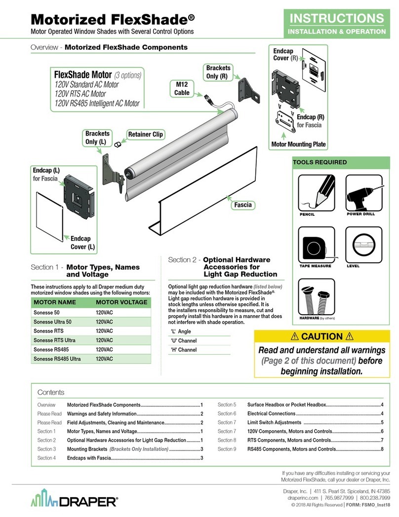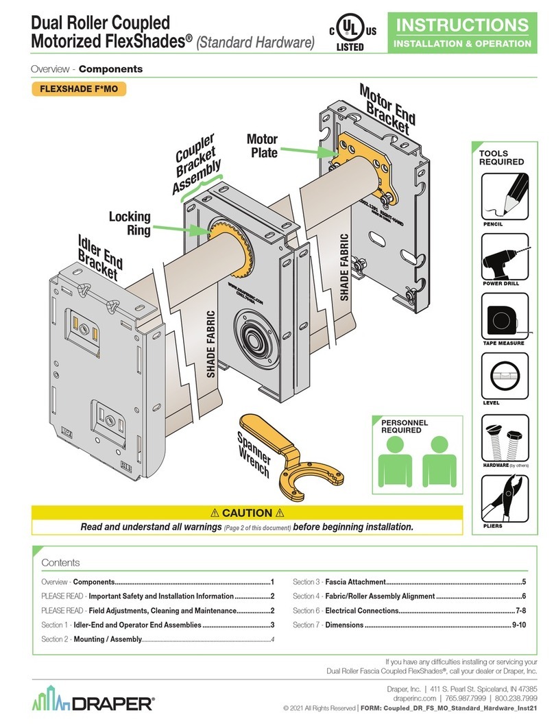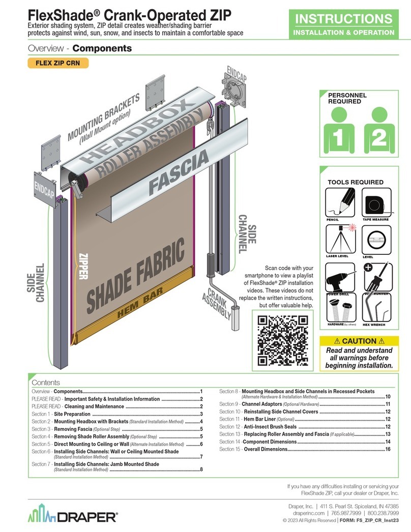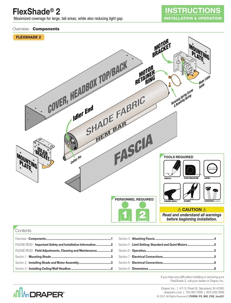
Page 4 of 6
.draperinc.com (765) 987-7999
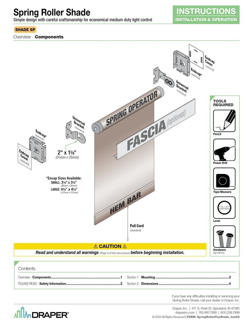
Lightbloc FlexShade®—Small Hardware by Draper
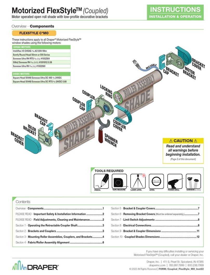
Limit Switch Adjustments—Standard and Quiet Motors
Push Button Limits
1Fully depress both limit switch push buttons, then operate wall switch to
make sure system works properly.
2Raise shade to desired “up” stop position.
3Set upper limit by depressing and releasing the proper (back) push button.
4Lower shade to desired “down” stop position.
5Set lower limit by depressing and releasing the proper (front) push button.
CAUTION: Be sure all switches are in “off” position before adjusting limit
switches. Always be prepared to shut off manually when new adjustment is
being tested. Do not allow the shade roller to become exposed by run-
ning the shade fabric too far down. Shade may be severely damaged if
allowed to run too far up or down. Eachshade’slimitswitchmustbesetifus-
inggroupcontrolsystem.Motor should be installed so limit switches are
pointed down or accessible.
Electrical Connections
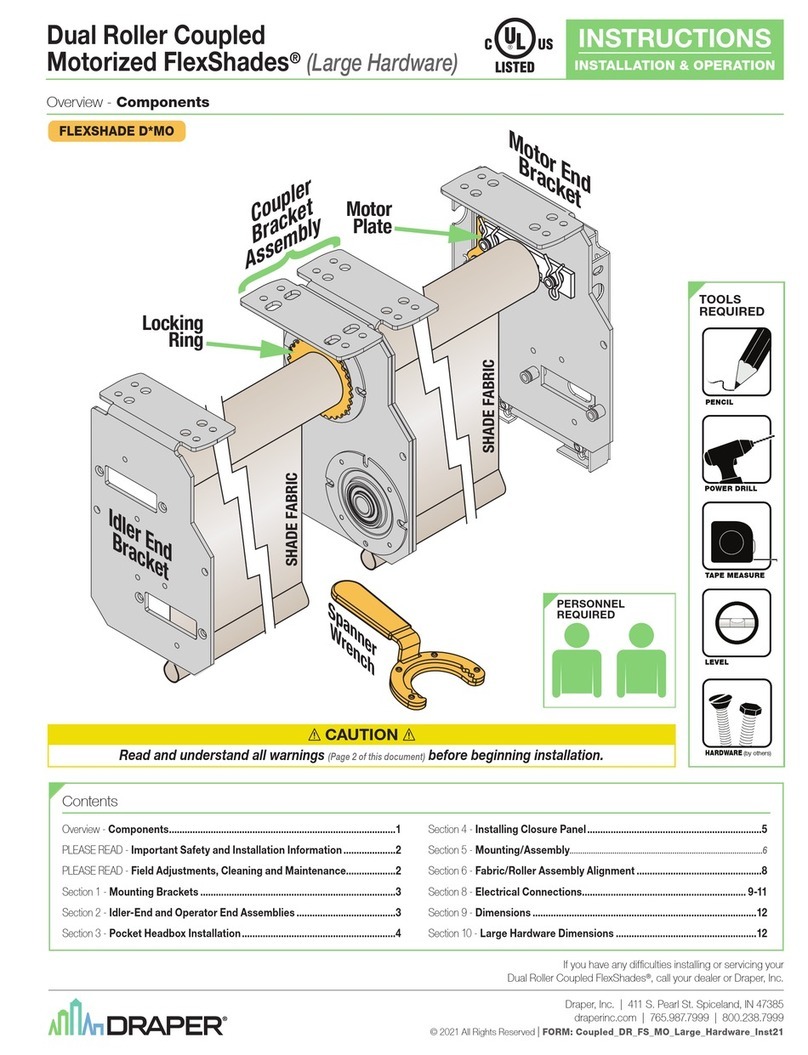
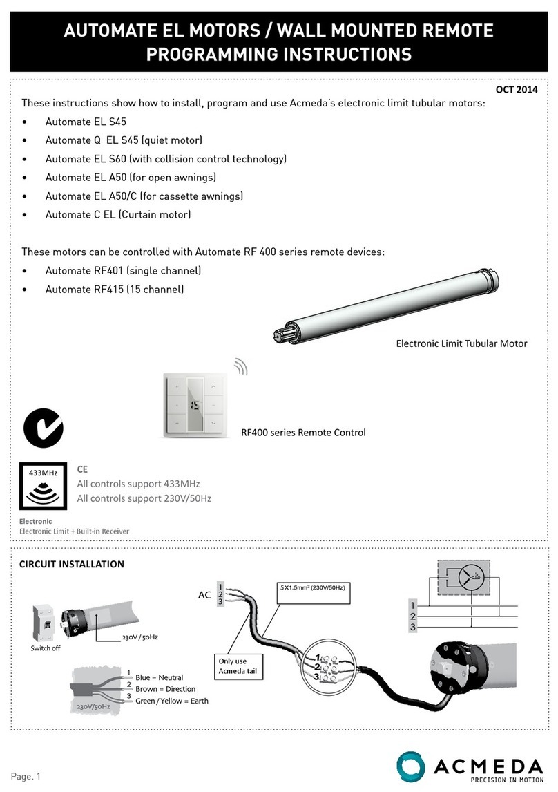
Motorized shade operates on 110-120V, 60 Hz. current. Shade is shipped with
internal wiring complete and control switch(es) fully boxed, and standardly
supplied with a 6' cable lead. Longer lead can be substituted by removing
two screws in motor end of roller, removing lead, plugging new lead in, and
replacing screws. Wire to connect shade to switch(es) and switch(es) to power
supply should be furnished by installer. Connections should be made in accor-
dance with attached wiring diagram, and wiring should comply with national
and local electrical codes.DO NOT wire motors in parallel without written
permission from Draper.
All operating switches should be “off” before power is connected.
Cleaning and Maintenance
Idlers on motorized shades may occasionally need lubrication. If lubrica-
tion is required, apply a small amount of a lithium based grease direct to the
idler pin.
Most of Draper’s standard fabrics may be cleaned at the window by
vacuuming with a soft brush attachment. They may also be cleaned by using
a sponge or soft cloth and mild solution of warm soapy water. A dishwashing
liquid, such as Ivory liquid, is recommended. A clean dry cloth is recommend-
ed for the metal finish. Exceptions are Flocké, Roc-Rol and Phifer SW7000
fabrics, which must be cleaned with a dry art sponge.
Please Note: Forlowvoltagewiringrequirements,Draperrecommendscon-
sultingwithaprofessionallowvoltageelectricalcontractor.Itisveryimportant
that shielded and stranded CAT 5 cable be used to prevent any electrical
interference.
Figure 15
Slat Bar
Catch
Sill Channel
NOTE: Opaque caulking around perimeter of cover, side channels, and
sill may be necessary for complete light block—especially for jamb
mounts where window openings are not square.
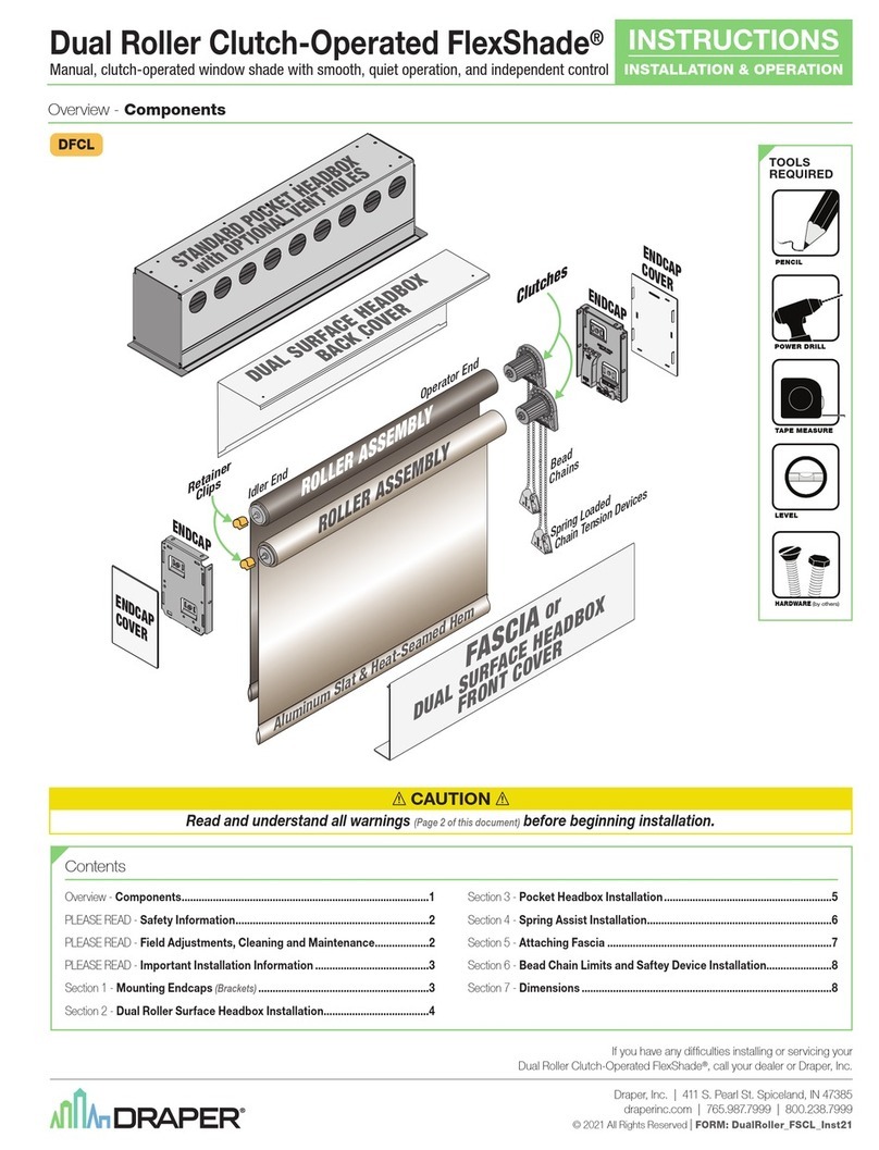
P-Clip Cord Tension Device
Figure 16
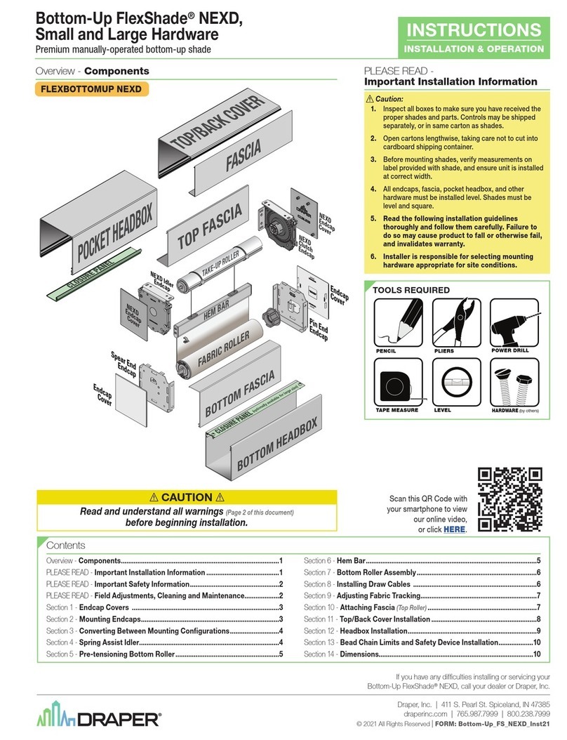
8Draper Bead Chain Clutch Operated shades that do not comply with
WMCA/ANSI Standard A100.1-2012 come with a cord tension device pre-
attached to bead chain (see Fig. 16). This device must be attached to wall,
jamb or sill so that the bead chain is held taut enough that children cannot
pull it away from the wall or fit their head into the loop. See safety note on
page 1.
Spring-Loaded Cord Tension Device
If your Draper Clutch FlexShade
®
complies with WMCA/ANSI Standard
A100.1-2012, a Spring-Loaded Cord tension device comes installed on bead
chain (see Fig. 17). An approved permanent warning label is attached, and
approved mechanical fasteners (wood screws) are included. Install cord ten-
sion device to wall, jamb or sill. To install, pull tensioner down so that the bead
chain is held taut and use the mounting hardware to keep it taut. The bead
chain should be taut enough so it will move smoothly through the device. If
there is not enough tension, the device will not allow the bead chain to pass
through and operate the shade. This device is designed so that children can-
not pull the bead chain away from the wall or fit their head into the loop. See
safety note on page 1. The installer is responsible for selecting mount-
ing hardware appropriate for site conditions. For more information, visit:
http://www.draperinc.com/WindowShades/WCMAcompliance.asp.
Attaching to Wood or Metal
1For attaching to wood, two #8-18 x 1.5" Zinc HWH TEK Type AB wood
screws are provided. For attaching to metal, choose fasteners with a mini-
mum fastener manufacturer-rated or tested release force of 20 lb (89 N),
and make sure they are long enough for the threads to catch and hold.
2Mark mounting hole locations with a pencil.
3Drill pilot holes smaller than the screw size.
Figure 17
JAMB MOUNT SILL MOUNT
Spring-Loaded
Clamp
JambMount SillMount
Tensioner
Installation through Drywall
1Make sure that screws are long enough for the threads to catch and hold
joist or stud.
2Locate the stud and mark it with a pencil.
3Mark mounting hole locations.
Please note: Ifyouareunabletomountonastud,useMollyBoltsorToggle
Bolts.Thefastenersshallhaveaminimumfastenermanufacturer-ratedor
tested release force of 20 lb (89 N).
4Drill shallow pilot holes smaller than the screw size.
5Pass screws through the Spring Loaded Tension Device. Turn the screws
into the pilot hole, starting by hand. The fasteners shall have a minimum
fastener manufacturer-rated or tested release force of 20 lb (89 N).
4Pass screws through the Spring Loaded Tension Device. Turn the screws
into the pilot hole, starting by hand.
Please Note: Tighten screws so that the Spring Loaded Tension Device
maintainsenoughtensiononthebeadchainforshadetooperatewithout
working loose, but not tight enough that the Spring Loaded Tension Device is
damagedbyovertightenedscrews.
Please Note: Tighten screws so that the Spring Loaded Tension Device
maintainsenoughtensiononthebeadchainforshadetooperatewithout
working loose, but not tight enough that the Spring Loaded Tension Device is
damagedbyovertightenedscrews.
