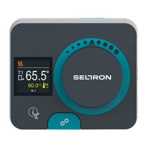
Seltron AHC40 User manual

AHC40
ENG Compact controller
DEU Kompaktregler
ITA Regolatore compatto
SLO Kompaktni regulator


English 3
AHC40
COMPACT CONTROLLER
AHC40 is a modern weather-compensated heating controller. Its design is compact and it
comes with a mixing valve actuator.
INTRODUCTION

4 English
CONTENTS
Introduction............................................................................................................................3
INSTRUCTIONS FOR USE
Appearance of the controller .................................................................................................5
Controller setup at the rst start-up .......................................................................................6
Step 1 – Language selection........................................................................................6
Step 2 – Selection of hydraulic schematic....................................................................6
Step 3 – setup of heating curve slope ..........................................................................7
Step 4 – selection of opening direction of the mixing valve..........................................7
Graphic LCD..........................................................................................................................8
Description and appearance of the display ..................................................................8
Symbols for the description of the operating mode ......................................................9
Symbols of user functions ............................................................................................9
Symbols for the display of temperatures and other data............................................10
Symbols of protection functions .................................................................................10
Symbols for the display of communication between
interconnected devices...............................................................................................10
Symbols for notications and warnings ......................................................................11
Display for help, notications and ERRORS .......................................................................11
Menu entry and navigation ..................................................................................................12
Building and menu description ............................................................................................12
Temperature setup .....................................................................................................14
User functions ............................................................................................................15
Operating mode selection ..........................................................................................16
Selection and setup of time programs........................................................................17
Basic settings .............................................................................................................19
Data review ................................................................................................................21
INSTRUCTIONS FOR SERVICE SETTINGS
Controller parameters..........................................................................................................22
User parameters.........................................................................................................22
Heating curve .............................................................................................................24
Service parameters ....................................................................................................27
SPECIAL PARAMETERS...........................................................................................31
Factory settings ..........................................................................................................32
Description of the mixing cycle operation...................................................................32
Operating modes in the event of sensor failure..........................................................34
INSTALLATION INSTRUCTIONS
Controller installation...........................................................................................................35
Electrical connection of the controller..................................................................................36
Connection of temperature sensors ...........................................................................36
Connection of the RCD room unit ..............................................................................37
BUS connection of the AHC controllers......................................................................37
BUS connection of the WDC and AHC controllers .....................................................38
BUS connection of the WXD and AHC controllers .....................................................38
Technical data: ...........................................................................................................39
Disposal of the old electrical and electronic equipment.......................................................40
Hydraulic schemes ...........................................................................................................155

English 5
INSTRUCTIONS FOR USE
APPEARANCE OF THE CONTROLLER
1
2
3
4
5
8
9
10
6 7
1. Graphic display
2. Manual operation clutch
3. Key Move backwards
4. Key Move left or reduction
5. Key Menu entry or selection conrmation
6. Key Move right or increase
7. Key Help
8. LED display – Rotation of the valve to the right
9. LED display – Operating status of the controller
– Green light: normal functioning of the controller
– Red light: error
10. LED display – Rotation of the valve to the left

6 English
CONTROLLER SETUP AT THE FIRST START-UP
The controller features an innovative solution “Easy start" allowing the initial setup of the
controller in only four steps.
Upon the rst connection of the controller to the power supply network, the rst step of the
controller setup is displayed after the program version and logo.
STEP 1 – LANGUAGE SELECTION
Select the preferred display language. Move among
languages with the keys and .
Conrm the selected language with the key .
Conrm the correct language selection by pressing .
If the wrong language has been selected in error,
return to language re-selection by pressing .
STEP 2 – SELECTION OF HYDRAULIC SCHEMATIC
Select the hydraulic schematic for the operation of the
controller. Move among schematics with the keys
and .
Conrm the selected schematic by pressing .
Conrm the correct schematic selection by pressing
.
If the wrong schematic has been selected in error,
return to schematic re-selection by pressing .
Hydraulic schematic can later be changed with the S1.1 service parameter.

English 7
STEP 4 – SELECTION OF OPENING DIRECTION OF THE MIXING VALVE
Select the right direction of opening the mixing valve.
Move between the directions with the keys and .
Conrm the selected direction with the key .
Conrm the correct direction by pressing .
If the wrong direction has been selected in error, return
to direction re-selection by pressing .
Opening direction of the mixing valve can be changed with the S1.4 service
parameter later on.
STEP 3 – SETUP OF HEATING CURVE SLOPE
Setup the heating curve slope. Change the value with
the keys and .
Conrm the selected value by pressing .
Conrm the heating curve slope with the key .
If the wrong value has been selected in error, return to
slope re-selection by pressing .
The heating curve slope can be changed with the P2.1 user parameter later
on.

8 English
GRAPHIC LCD
All relevant data on the operation of the controller can be seen on the graphic LCD.
DESCRIPTION AND APPEARANCE OF THE DISPLAY
Notications and
errors
Operating mode and
user functions
Data display:
operating mode, user functions, notications and errors are shown in the upper half of the
display. To switch between the data display and display of the hydraulic schematic use the
key .
To review temperatures and other data use the keys and . The number of sensors
and other data that is displayed depends on the selected hydraulic schematic and control-
ler setup.
To recall certain data after the use of keyboard, search for it with the keys
and and conrm it by pressing and holding for 2 seconds.
By pressing and holding the key for 2 seconds, the temperature display
changes from one-line to two-line display or vice versa (only if the condition
P1.9=0 is met). In the two-line temperature display (P1.9=1), the rst line
shows the measured temperature value and the second one the preferred or
calculated temperature.
Hydraulic schematic with
the temperature display
Room unit
Temperature, protection functions and
display of other data

English 9
Symbol Description
Space heating
Cooling
Operation based on the time program – day intervals. *
Operation based on the time program – night intervals. *
Operation based on to the preferred day-time temperature.
Operation based on to the preferred night-time temperature.
Switch-o
Manual operation
* The number indicates the selected time program.
SYMBOLS FOR THE DESCRIPTION OF THE OPERATING MODE
Symbol Description
PARTY operating mode
ECO operating mode
Vacation operating mode
Automatic switch-o of heating
Floor foundation drying
Operation of the supply line with a constant temperature
Boost heating
SYMBOLS OF USER FUNCTIONS

10 English
SYMBOLS FOR THE DISPLAY OF TEMPERATURES AND OTHER DATA
Symbol Description
The measured temperature value
Room temperature
Outdoor temperature
Temperature of the boiler or heat source
Temperature of the supply line
The temperature of the return line
T1, T2, T3, T4
TR
TA
TQ
Temperature value measured with sensors T1, T2, T3 and T4
Temperature value measured with a room sensor or room unit
Outdoor temperature, obtained through the BUS connection
Temperature of the heat source, obtained through the BUS connec-
tion
SYMBOLS OF PROTECTION FUNCTIONS
Symbol Description
Protection of the heat source against overheating
Protection against freezing due to low room temperature
Protection against freezing due to low outdoor temperature
SYMBOLS FOR THE DISPLAY OF COMMUNICATION BETWEEN
INTERCONNECTED DEVICES
Symbol Description
Devices, connected to the COM communication line
Room unit is connected. The number of the room unit indicates
whether it is the rst or the second room unit.
Controller status of the BUS connection
First controller of the BUS connection
Interim controller of the BUS connection
Last controller of the BUS connection

English 11
DISPLAY FOR HELP, NOTIFICATIONS AND ERRORS
Recall the display for help, notications and error by pressing . The display oers the
following options:
Brief instructions
Brief instructions for use of the controller.
Controller version
Display of the controller type and software version.
Notications
List of transgressions of maximum temperatures and activation of protection
functions. Press and to can move through the list of notications. Exit
the list by pressing .
Errors
List of errors of sensors and other assemblies.
Press and to can move through the list of errors. Exit the list by press-
ing .
Deleting notications and errors
List of notications and errors shall be deleted.
Caution: Sensor errors that are essential for controller operation cannot be
deleted.
Symbol Description
Notications
In case of a transgression of the maximum temperature or activation
of the protection function, the controller will trigger a warning with
ashing of the symbol on the display. If the maximum temperature is
no longer exceeded or if the protection function is already switched
o, the lit-up symbol will indicate a recent event. Recall the display for
the review of the list by pressing . After reviewing the list of notica-
tions, the notication symbol disappears.
Errors
In case of a failure of sensors or communication connections, the
controller will trigger a warning with ashing of the symbol on the
display. If the error is eliminated or no longer present, a non-ashing
symbol will indicate a recent event. Recall the display for error list re-
view by pressing . After reviewing the list of errors, the error symbol
disappears.
SYMBOLS FOR NOTIFICATIONS AND WARNINGS

12 English
MENU ENTRY AND NAVIGATION
To enter the menu press .
Use and to move around the menu, and to conrm your selection.
Return to the previous display by pressing .
If no key is pressed for 15 seconds, the display becomes dimmed. After the
delay of the display switch-o, the display will switch o. The time can be set
up in the menu Basic settings, Display settings.
BUILDING AND MENU DESCRIPTION
TEMPERATURE SETUP
Day-time temperature
Night-time temperature
USER FUNCTIONS
PARTY operating mode
ECO operating mode
Vacation operating mode
Function switch-off
OPERATING MODE SELECTION
Operation based on the selected time program
Operation based on the daily temperature
Operation based on the night-time temperature

English 13
Switch-off
Selection of cooling or heating operation
Manual operation
TIME PROGRAMS
First time program
Second time program
Third time program
Fourth time program
BASIC SETTINGS
User language
Time and date
Display settings
Delay for the switch-off of the display and automatic exit from the menu
DATA REVIEW
Graphic display of temperatures according to days of the last week
Detailed graphic display of temperatures for the current day
Meters of operating hours of controller outputs
Special service data
USER PARAMETERS
General settings
Heating circuit settings
Energy source settings

14 English
TEMPERATURE SETUP
The menu displays temperatures that can be set up as preferred in the selected hydraulic
schematic.
Select the preferred temperature with the keys , and . The display for the tem-
perature setup opens up:
Use the keys and to set up the preferred temperature and conrm it by pressing .
Exit the setup by pressing .
Factory value
Graphic
display of the
setup
Setup range
The last conrmed setup
value
Current value of the
preferred tem-
perature (numeric
display)
Current value of the
preferred temperature
SERVICE PARAMETERS
General service settings
Service settings for the heating circuit
Service settings for energy sources
SPECIAL PARAMETERS
Parameters for oor foundation drying
FACTORY SETTINGS
Reset of the controller parameters
Reset of the controller and restart of the rst setup
Reset of time programs
Save user settings
Load user settings

English 15
USER FUNCTIONS
PARTY function allows operation based on the preferred comfortable temperature.
Select the function PARTY with the keys and turn it on by pressing . To set up the
function time tracker and preferred temperature, re-select the icon .
With the keys and select the desired temperature to change and press . The
value starts to ash. Change the value with the keys and and conrm it by pressing
.
Exit the setup by pressing .
PARTY operating mode
User functions provide additional comfort and benets in using the controller. In the menu,
the following user functions are available:
ECO function allows operation based on the preferred saving temperature.
Select the function ECO with the keys and turn it on by pressing . To set up the
function time tracker and preferred temperature, re-select the icon .
With the keys and select the desired temperature to change and press . The
value starts to ash. Change the value with the keys and and conrm it by pressing
.
Exit the setup by pressing .
ECO operating mode
Vacation function allows operation based on the preferred saving temperature until the set
date.
Select the function Vacation with the keys and turn it on by pressing . To set up
the function date tracker and preferred temperature, re-select the icon .
Now select the temperature to change with the keys and and press . The value
starts to ash. With the keys and select the temperature to change and conrm it by
pressing .
Exit the setup by pressing .
Vacation operating mode
All user functions can be switched-o at anytime. This can be done by select-
ing the icon .

16 English
OPERATING MODE SELECTION
In the menu, choose the preferred operating mode of the controller.
Operation is based on the selected time program.
Operation based on the selected time program
Operation is based on to the preferred day-time temperature.
Operation based on the daily temperature
Operation is based on the preferred night-time temperature.
Operation based on the night-time temperature
The controller is switched o. In the "Heating” mode, the protection against freezing re-
mains active, and in the “Cooling” mode the protection against overheating.
Switch-o
If heating is selected, it is then switched to cooling.
If cooling is selected, it is then switched to heating.
By conrming the icon by pressing , the heating switches to cooling and vice versa.
Selection of cooling or heating operation
For the operation of cooling, the system for the intake of cooling water must be
on.

English 17
Use the keys and , to move among individual
outputs R1, M+ or M-. Select the output to change the
status of by pressing .
The value ON, OFF or AUTO starts to ash. Now the
output status can be changed by pressing and .
Conrm the setup by pressing .
Exit the list by pressing .
This mode is used for testing the control system or in the event of a failure. The control
output can be manually switched on, switched o or automatic operation can be selected.
Manual operating mode
SELECTION AND SETUP OF TIME PROGRAMS
Weekly time programs enable automatic switching between the preferred day and night-
time temperature. There are four time programs available. Use the keys and to
select the preferred time program and conrm it by pressing .
The selected time program can be changed by re-conrming it by pressing . A new
display will open up:
Changing the time program
First time program
Second time program
Third time program
Fourth time program
Time axis
Copying the time programEditing of the time program
Number of time program Selected day

18 English
With the keys , and , select the day to change the course of the program for or
the one to copy in other days. With the keys , and select the icon for edit-
ing and or the icon for copying the time program.
Editing of the time program
A new display will open up showing the time program
and three icons for changing the program.
With the keys and select the preferred command icon and conrm it by pressing
. A cursor appears on the time axis. With the keys and draw the preferred course of
the time interval. Finish drawing the interval by re-pressing .
Exit the editing of the time program by pressing .
- Free moving of the cursor.
- Drawing of the switch-o interval or night
temperature.
- Drawing of the switch-on interval or day
temperature.
Copying the time program
A new display will open up showing the time program
for the selected day. At the top of the display there is
a eld for the selection of the day or group of days to
copy the time program in. With the keys and
the day or group of days can be selected. For copying
press the key . Exit copying by pressing .
Initial settings of time programs
Time program Day Switch-on interval
MON–FRI 6am–10pm
SAT–SUN 7am–10pm
MON–FRI 5am–7.30am, 1.30pm–10pm
SAT–SUN 7am–10pm
MON–FRI 6am–8.30am, 11am–1.30pm, 4pm–10pm
SAT–SUN 7am–10pm
MON–FRI 2pm–10pm
SAT–SUN 7am–10pm

English 19
BASIC SETTINGS
The menu is intended for setting up the language, time, date and display.
User language
Select the preferred user language with the keys , and conrm it by pressing .
Exit the setup by pressing .
Time and date
Set up the exact time and date in the following way:
Use the keys and , to move among individual
data. Select the data to change by pressing . If
the data starts to ash, it can be changed with the
keys and and conrmed it by pressing .
Exit the setup by pressing .

20 English
The following setup is available:
delay for the switch-o of the display and automatic exit from the menu.
Display setup
Conrm the preferred setup by pressing .
A new display will open up:
Graphic
symbol
Factory value
Current setup value
Current value
setup (graphic dis-
play)
Setup range
The last conrmed setup
value
Current value
setup (numerical dis-
play)
Change the setup with the keys and conrm it by pressing .
Exit the setup by pressing .
The setup will be changed after it has been conrmed with key .
Table of contents
Languages:
Other Seltron Controllers manuals
