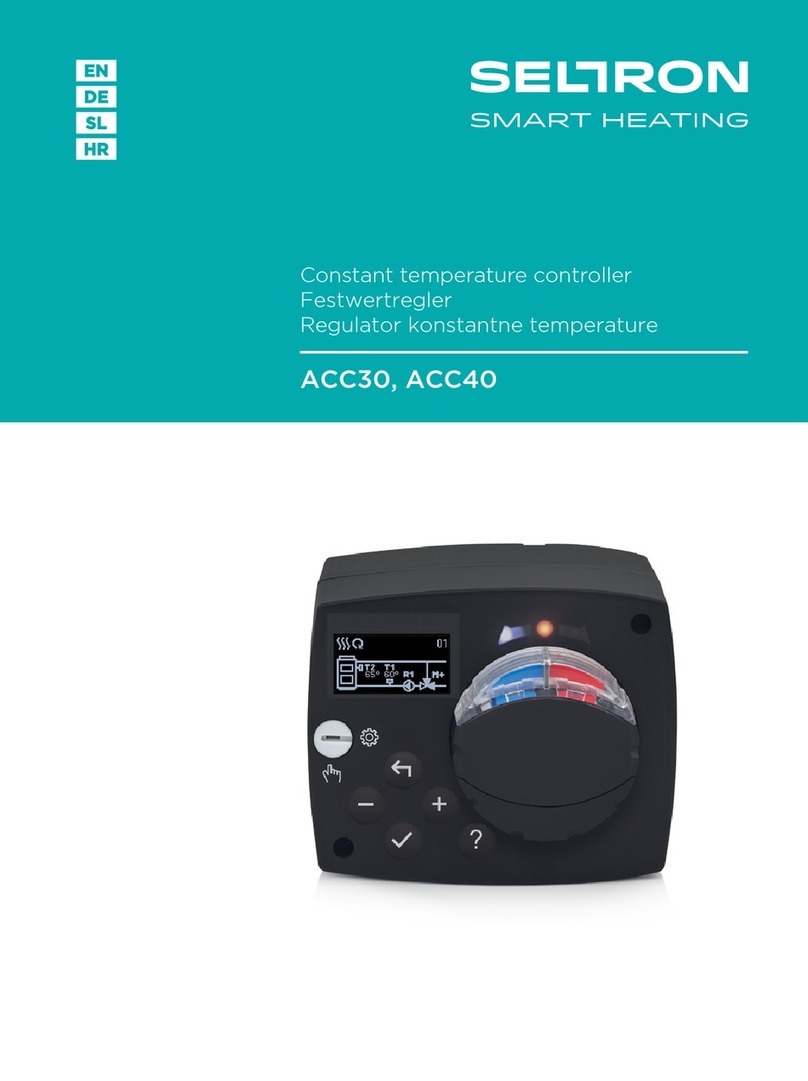
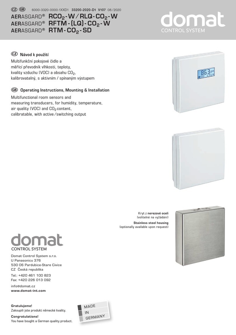
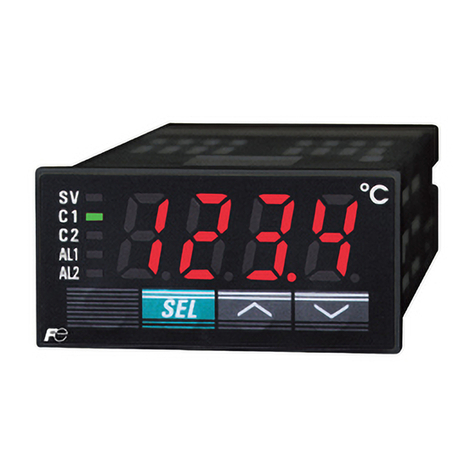
Seltron ACC40 User manual

ACC30, ACC40
ENG Constant temperature controller
DEU Festwertregler
SLO Regulator konstantne temperature


English
1
CONSTANT TEMPERATURE CONTROLLER
ACC30, ACC40
Controllers ACC30, ACC40 are modern designed, microprocessor-driven devices made
with digital and SMT technology.
The controller are provided as a constant temperature controller with actuator designed
for heating applications. The most common use is to control the return temperature in the
boiler. Controller ACC40 besides controlling the actuator also controls the circulating pump.
For initial setup see Initial controller setup, page 6!
INTRODUCTION

2 English
Contents
Introduction..................................................................................................................... 3
Appearance of the controller .......................................................................................... 5
Initial controller setup...................................................................................................... 6
Step 1 - Language selection................................................................................... 6
Step 2 - Hydraulic scheme selection ...................................................................... 6
Step 3 - Opening of the mixing valve...................................................................... 7
Graphic LCD display....................................................................................................... 8
Description and design of the main display............................................................ 8
Descpription of symbols on the display .......................................................................... 9
Controler mode symbols......................................................................................... 9
Temperature and other data symbols..................................................................... 9
Symbols for notices and warnings.......................................................................... 10
Display for help, notices and warnings........................................................................... 10
Menu entry and navigation ............................................................................................. 11
Menu structure and description ...................................................................................... 11
Temperature settings.............................................................................................. 13
Operation mode ..................................................................................................... 14
Manual mode:......................................................................................................... 14
Heating or cooling operation mode selector................................................................... 14
Basic settings ................................................................................................................. 15
Data overview................................................................................................................. 17
Controller parameter and auxiliary tools......................................................................... 18
Basic parameters.................................................................................................... 18
Service parameters ................................................................................................ 20
Factory settings ...................................................................................................... 23
Operation mode by sensor Failure ................................................................................. 24
Controller installation...................................................................................................... 25
Controller’s electric connection ...................................................................................... 25
Technical data................................................................................................................. 26
Disposal of old electrical & electronic equipment ........................................................... 27
Notes .............................................................................................................................. 28
Hydraulic schemes ......................................................................................................... 81

English
3
USER MANUAL
APPEARANCE OF THE CONTROLLER
1
2
3
4
5
8
9
10
6 7
1. Graphic display
2. Clutch for manual operation.
3. Button Return back.
4. Button Move to left, decreasing.
5. Button Menu entry, conrmation of selection.
6. Button Move to right, increasing.
7. Button Help.
8. LED indication - valve rotation right.
9. LED indication red - fault, error.
10. LED indication - valve rotation left.

4 English
INITIAL CONTROLLER SETUP
Constant temperature controllers are equipped with an innovative solution, which allows
initial setup of the controller in only three steps.
When you connect the controller to the power supply for the rst time, the software version
is shown. Next, the rst step appears on the screen.
STEP 1 - LANGUAGE SELECTION
Using buttons and you select the required
language.
Press the button to conrm the selected language.
After selecting the language, the controller requires
conrmation of the selection by pressing the
button .
If you accidentally selected the wrong language, go
back to reset the language by pressing button .
STEP 2 - HYDRAULIC SCHEME SELECTION
Next, you select a hydraulic scheme for the control-
ler function. Move between schemes by means of
buttons and .
Conrm the selected scheme by pressing the
button .
After you selected the scheme, the controller re-
quires conrmation of the selection by pressing the
button .
If you accidentally selected the wrong scheme, go
back to reset the scheme by pressing button .
Selected hydraulic scheme can be later changed with service parameter
S1.1.

English
5
STEP 3 - OPENING OF THE MIXING VALVE
Press icon which indicates the proper direction of
mixing valve opening direction. Between icons you
can move with buttons and .
After you selected the correct direction, the controller
requires conrmation of the selection by pressing the
button .
If you accidentally selected the wrong mixing valve
opening direction, go back to reset the the selection
by pressing button .
Selected mixing valve opening direction can be later changed with service
parameter S1.4.

6 English
GRAPHIC LCD DISPLAY
All important data of controller operation are shown on the graphic LCD display.
DESCRIPTION AND DESIGN OF THE MAIN DISPLAY
Notications
and warnings.
Controller mode. Controller mode.
Temperature, protection functions and over-
view of other data.
Display of information on the screen:
The controller mode, notications and warnings are displayed in the upper third of the
display. For switching between basic display and display of the hydraulic scheme use the
button .
To check the temperature and other data, use buttons and . The number of sensors
and other data, which can be listed on the display, depends on the selected hydraulic sche-
me and controller settings.
If you would like to have a specic data display to appear after you stop using
the keyboard then select the desired data with buttons and . Conrm
the selected screen by pressing the button for 2 seconds.
When you press the button for 2 seconds, then the display of the tem-
perature will change from one to two rows and vice versa. On the two line
temperature display, the measured temperature is displayed in the rst row
and the required or calculated temperatire in the second row.

English
7
DESCPRIPTION OF SYMBOLS ON THE DISPLAY
Symbol Description
Heating.
Cooling.
Automatic mode.
Stand by.
Manual mode.
CONTROLER MODE SYMBOLS
TEMPERATURE AND OTHER DATA SYMBOLS
Symbol Description
Measured temperature.
Set point or calculated temperature.
Supply temperature.
Boiler temperature.
Stand- pipe temperature.
Stand- pipe temperature.
Boiler return temperature.
T1, T2 Temperature measured by the sensor T1, T2.

8 English
DISPLAY FOR HELP, NOTICES AND WARNINGS
By pressing the button the screen for help, messages and warnings will be oppened in
which the following icons are available.
Short manual
Short manual for use of the controller.
Controller version
Overview of controller type and software version.
Notications
Log of exceeded maximum temperatures and activated protection functions.
By pressing the buttons and move through the list of notications.
Press to exit the list.
Warnings
Log of sensors, pump or ow meter failures.
By pressing the buttons and move through the list of warnings.
Press to exit the list.
Delete warning and notication logs
By pressing the button will erase notication and warning log. All sensors
that are not connected will be deleted from the list of failures.
Note: Failures of sensors that are required for controller operation can not
be deleted.
Symbol Description
Notications
In case of exceeding the maximum temperature or activation of pro-
tection function, the controller indicates the event with ashing symbol
on the display. If the maximum temperature is no longer exceeded or
if the protection function is turned o, a lited symbol indicates a recent
event.
Press to open the screen to check notications.
Warning
In the event of sensor failure, the controller indicates the failure with
ashing symbol on the display. If the issue is resolved or no longer
present, a lited symbol indicates a recent event.
Press to open the screen to check warnings.
SYMBOLS FOR NOTICES AND WARNINGS

English
9
MENU ENTRY AND NAVIGATION
To enter the menu, press the button .
Move around the menu using the buttons and , with the button you conrm your
selection.
By pressing the button you return to the previous screen.
If some time no button is pressed, the backlight turns o or is reduced accor-
ding to the setting.
MENU STRUCTURE AND DESCRIPTION
TEMPERATURE SETTINGS
Set-point temperature.
OPERATION MODE
Automatic operation.
Switch-off.
Select Heating / Cooling mode.
Manual operation.
BASIC PARAMETERS
Language selection.
Time and date.
DISPLAY SETTINGS
Duration of active display illumination and menu autoexit.

10 English
DATA OVERVIEW
Diagrams of measured temperatures by days for last week.
Diagrams of measured temperatures for current day.
Output operation time counter.*
Special service data.
CONTROLLER PARAMETERS
Basic settings.
Settings for the heating circuit.*
Settings for heat source.*
SERVICE PARAMETERS
Basic settings.
Settings for the heating circuit.
Settings for heat source.
FACTORY SETTINGS
Reset of all controller parameters.
Reset of all controller settings and restart of initial setup.
Save user settings.
Load user settings.
* Not available

English
11
TEMPERATURE SETTINGS
In the menu only the temperatures are displayed, where you can set the set-point tempera-
ture by the selected hydraulic scheme.
By pressing buttons , and you choose the required temperature, and a new
window opens:
Set the set-point temperature with buttons , and conrm with button .
Exit the settings by pressing the button .
Default value
Graphic review
of settings
Setting range
Value of the last
conrmed setting
Current value
of set-point
temperature
(numeric mode)
Current value
of set-point temperature
(analogue mode)

12 English
OPERATION MODE
In this menu the operating mode of the controller is selected.
Select the operaion mode with buttons , and conrm with button .
Exit the settings by pressing the button .
Automatic operation
Controller switch-o
Heating or cooling operation mode selector
Manual mode
HEATING OR COOLING OPERATION MODE SELECTOR
Heating operation mode is active.
Cooling operation mode is active.
MANUAL MODE:
This mode is used for testing the system or in case
of malfunction. Every output can be manually activa-
ted or deactivated.
Move with the buttons and between the indi-
vidual outputs R1, M- or M +. The output, which you
want to change is selected by pressing the button
.
ON, OFF or AUTO starts ashing. Now the output
can be changed using the buttons und . The
setting is conrmed by pressing the button .
Exit the setup menu with the button.

English
13
BASIC SETTINGS
The menu is intended for language, time, date and display settings
Language selection
The required user language is selected by pressing buttons , and conrmed with
button .
Exit settings by pressing the button .
Time and date
You set the exact time and date in the following
manner:
By pressing buttons and move among
individual data. By pressing button you select
data that you want to change. When data ashes,
change it by pressing buttons , and conrm it
with the button .
Exit the settings by pressing the button .

14 English
The following settings are available:
Time of active screen illumination and autoexit from menu to the main screen.
DISPLAY SETTINGS
By pressing buttons , and you select and conrm required setting.
A new window opens:
Graphic
symbol
Werkseinstellung
Aktueller Einstellwert
Current value of
setting (graphic)
Einstellbereich
The last conrmed
value of setting
Current value of setting
(Numeric value)
You change settings by pressing buttons and and conrm by pressing
button .
Exit the settings by pressing button .
The change of settings is carried out when you conrm it by pressing button
.

English
15
To view the sensor-diagrams move with buttons and between the sen-
sors. By pressing the button the date of displayed temperature begins to
ash. Use buttons and to move between days.
Return to the temperature selection by pressing the button .
The range of the temperature display on the graph can be changed with the
the button .
Exit the diagram overview by pressing the button .
DATA OVERVIEW
In this menu there are icons to access the following data on controller performance:
DIAGRAMS OF MEASURED TEMPERATURES BY DAYS FOR LAST WEEK
The graphical representation of the temperature prole in days, for each sensor.
There are records of the temperatures for the last week of operation.
DIAGRAMS OF MEASURED TEMPERATURES FOR CURRENT DAY
Detailed graphic overview of temperature in current day for each sensor.
How often are temperatures logged is set with parameter P1.3.
OUTPUT’S OPERATION TIME COUNTERS*
Counters of controller’s outputs operation time.
SPECIAL SERVICE DATA
Intended for diagnostics for technical service.
* Not available

16 English
CONTROLLER PARAMETER AND AUXILIARY TOOLS
SERVICE MANUAL
All additional settings and adjustments of controller performance are carried out by means
of parameters. User-, Service- and parameters are found on the second menu screen.
BASIC PARAMETERS
The basic parameters are listed in one group P1 - basic parameters.
Content of basic parameters is displayed as follows:
Parameter mark
Parameter
description
Current parameter
value
Factory default
Setting range
The setting is changed by pressing the button .
The value will start blinking and can be changed with the and . The setting is conr-
med by pressing the button .
Move with buttons and to other parameters and repeat the procedure.
Exit the parameter settings by pressing the button .

English
17
Basic parameters:
Para-
meter
Function Parameter description Setting range Default
value
P1.1 TEMPERATURE ROUND
UP
You set the accuracy of displayed temperatures. 0- 0.1 °C
1- 0.2 °C
2- 0.5 °C
3- 1 °C
2
P1.2 AUT. SHIFT OF CLOCK
TO SUMMER/WINTER
TIME
With the help of a calendar, the controller carries out
the automatic changeover between summer and winter
time.
0- NO
1- YES 1
P1.3 PERIOD OF TEMPERAT.
LOGGING
By setting this eld you dene how often the measured
temperatures are saved.
1 ÷ 30 min 5
P1.4 TONES By setting this eld you dene sound signals of the
controller.
0- OFF
1- KEYPAD
2- ERRORS
3- KEYPAD AND
ERRORS
1
P1.5 ADVANCED TEMPERA-
TURE SCREEN
Advanced screen means that while checking
temperatures you can see measured and required or
calculated temperature.
0- NO
1- YES 1

18 English
SERVICE PARAMETERS
Service parameters are arranged in groups S1 - Basic parameters, S2 - Parameters for the
heating circuit. With service parameters it is possible to activate or select many additional
functions and adaptations of controller performance. When you select the required para
meter group in the menu, a new screen opens:
Parameter
mark
Parameter
description
Parameter value
Hydraulic scheme
The setting is changed by pressing the button . Because the parameters are factory
locked, a new screen appears. Here you have to enter the unlock code.
Setting range
Default value
This manual suits for next models
1
Table of contents
Languages:
Other Seltron Temperature Controllers manuals
