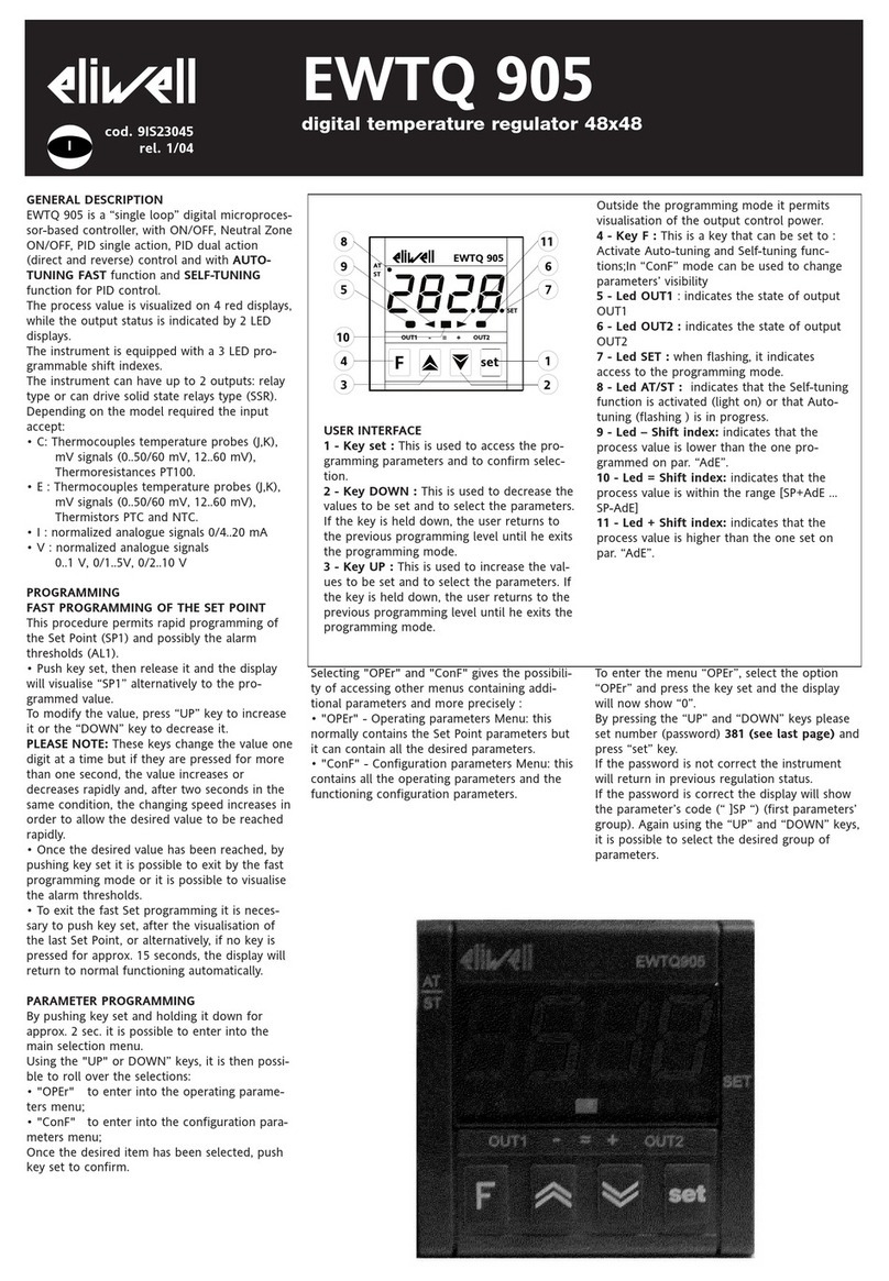
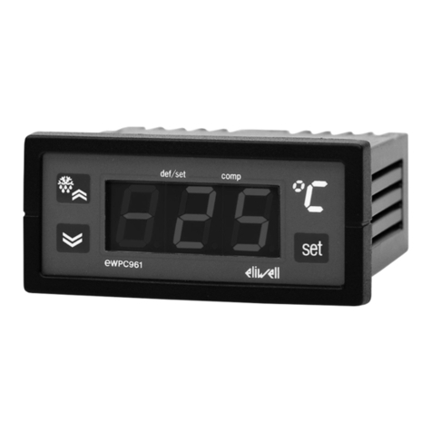
Eliwell EWPC 902/S Series User manual

GENERAL DESCRIPTION
The EWPC 902/S is a new series of micro-
processor based and fully programmable
process controllers for single setpoint ap-
plications.
The front keypad of these controllers offers
several alpha-numeric menu prompts to
configure the controller for each specific
application.
Furthermore, the instrument is equipped
with a RS-485 port for the purpose of con-
necting it into a Televis system; is compat-
ible with Televis software rel 2.4 or greater.
In case its use with different software re-
leases is required contact your supplier or
Eliwell Customers’ Service.
Three different versions of this controller
are available: EWPC 902/T/S for
Temperature, EWPC 902/R/S for Relative
humidity and EWPC 902/P/S for Pressure
control.
The EWPC 902/S is supplied in the popu-
lar “32x74” ELIWELL housing.
FRONT KEYPAD
SET: push to display the setpoint value.
The setpoint can be changed within 5 sec-
onds with the “UP” or “DOWN” button.
The control will automatically switch back
to normal operating mode within 5 sec-
onds; the last entered setpoint will stay in
memory.
UP: used to increase the setpoint value, as
well as the parameter when in program-
ming. When held down for a few seconds,
the change rate accelerates.
DOWN: used to decrease the setpoint val-
ue, as well as the parameter when in pro-
gramming. When held down for a few
seconds, the change rate accelerates.
Led “SET”: on during setpoint
display/change or blinking during program-
ming.
Led “OUT”: status light of the output.
PARAMETER PROGRAMMING
Programming is easily accessed by holding
the “SET” button down for more than 7
seconds; the first parameter is displayed
while the status light Led “SET” remains
blinking during the programming period.
Other parameters are accessed with the
“UP” and “DOWN” button. With the “SET”
button, the actual setting of each parame-
ter is displayed. To change a parameter
setting, push the “SET” plus the “UP” (or
“DOWN”). The system will automatically re-
turn to its normal operating mode a few
seconds after the programming procedure
is completed or interrupted.
DESCRIPTION OF PARAMETERS
diF: diFferential.
The switching differential (hysteresis) can
be set with positive value (make on rise) or
with negative value (make on fall).
LSE: Lower SEt.
This is the lower limit below which the user
cannot change the setpoint; normally set at
the lowest value recommended for the
sensor.
HSE: Higher SEt.
Similar to “LSE”, however setting an upper
limit for the setpoint.
Att: Alarm temperature type (“HAL” and
“LAL”).
Ab = absolute;
re = relative.
HAL: Higher ALarm.
Maximum temperature alarm. Maximum
temperature value – when exceeded the
information is sent to the Televis system.
LAL: Lower ALarm.
Minimum temperature alarm. When the
temperature reaches a lower value the in-
formation is sent to the Televis system.
Set to a negative value when parameter
“Att = re”.
AFd: Alarm (Fan) differential.
PAO: Power-on Alarm Override.
HOW IT IS MADE
• Dimensions: front 74x32 mm
(2.913x1.260"), depth 67 mm
(2.637")
• Mounting: flush panel mount with
mounting bracket
• Protection: the instrument front-
panel is waterproof IP65; an op-
tional snap-on cover can be
supplied to provide additional pro-
tection of the rear terminal block
• Connections: screw terminal block
(2.5 mm2; one wire each terminal
only, in compliance with VDE
norms)
• Output: one (1) SPDT relay 8(3)A
250VA
• Auxiliary output: 12 VC/60 mA (for
transducer power supply, e.g. hu-
midity sensor, pressure transducer,
etc.)
• Inputs (depending on model):
PTC / Pt100 / current (4…20 mA;
Ri = 41 Ω) for EWPC 902/T/S;
EWHS 28/31 for EWPC 902/R/S
and EWPA 007/030 for EWPC
902/P/S
• Serial connection: RS-485 serial
port for connection to the Televis
system
• Televis system compatibility: soft-
ware release 2.3.2 or greater
• Resolution: 1 °C (°F) or 0.1 °C (°F).
The right-most digit can also be
set to read-out in 0 or 5 only, or in
all 10 digits
• Accuracy: better than 0.5% of full
scale
• Power supply: 12…24 VA/C
WHAT IT IS
The EWPC 902/S is a series of mi-
croprocessor based and fully pro-
grammable process controllers for
single setpoint applications.
The instrument is equipped with a
RS-485 port for the purpose of con-
necting it into a Televis system.
Three different versions of this con-
troller are available: EWPC 902/T/S
for Temperature, EWPC 902/R/S for
Relative humidity and EWPC
902/P/S for Pressure control.
EWPC 902/S
temperature controller with Televis output

tAo: temperature Alarm override.
cPP: compressor Probe Protection.
Select compressor relay status in case of
room probe defect.
oF = compressor OFF in case of probe de-
fect;
on = compressor ON in case of probe de-
fect;
dc = NOT AVAILABLE.
ctP: compressor type Protection.
Select the type of (short-cycle) protection
best suited for the compressor; the actual
delay time is programmed with the next
parameter.
nP = no Protection;
don = delay on start; delay applies when
relay is energized;
doF = delay at switching oFf. Delay after
stop, i.e. time between stop and subse-
quent start;
dbi = delay between two successive starts.
Limits the number of start-ups per hour.
cdP: compressor delay Protection.
The time delay - in minutes - applicable to
the previous parameter “ctP”.
odo: output delay (at) on.
Time delay - in minutes - applied to activa-
tion of the relays after start-up.
CAL: CALibration.
Temperature read-out offset to allow for a
fixed adjustment up or down due to probe
location, if desired.
dEA: dEvice Address.
To select the (address) label of the device in
relation to the supervisory system.
FAA: FAmily Address.
To select the (family) label of the device in
relation to the supervisory system.
ndt: number display type.
Visualization number of display.
in = entire;
dE = decimal;
hF = half.
Lci: Lower current input.
For EWPC 902/R/S, EWPC 902/P/S and
EWPC 902/T/S with current input only.
Read-out corresponding to 4 mA input sig-
nal (factory set at 20 %R.H for EWPC
902/R/S).
Hci: Higher current input.
For EWPC 902/R/S, EWPC 902/P/S and
EWPC 902/T/S with current input only.
Read-out corresponding to 20 mA input
signal (factory set at 100 %R.H for EWPC
902/R/S).
PAS: PASsword.
Permits to set the password value.
0 = no password required to enter para-
meter programming;
1…15 = admitted values for the password.
rEL: rELease firmware.
Code of device version.
Hdc: Hardware code.
Read-only parameter indicating the hard-
ware code of the device.
tAb: tAble of parameters.
This shows the configuration of the para-
meters as set in the factory; can not be
modified (for factory identification and di-
agnostic purposes only).
INSTALLATION
The instrument is designed for flush panel
mount. Prepare a 71x29 mm panel cut-
out; insert the instrument through the front
and fasten with the U-bracket supplied
with the unit. The ambient temperature
around the instrument should be kept be-
tween –5…65 °C (23…149 °F).
Do not install the instrument in moist
and/or dirty places or near heat sources; it
is suitable for operation in environments
with an ordinary pollution level.
Leave enough room for air circulation by
the cooling holes of the instrument.
ELECTRICAL WIRING
The instrument is equipped with a screw
terminal block suitable for max 2.5 mm2
wiring (one wire each terminal only, in com-
pliance with VDE norms). Make sure that
the low voltage power supply matches re-
quirements: 12…24 Va/c.
According to the type, the probe shall be
connected according to the electric dia-
gram on the instrument body.
In case of Eliwell pressure or humidity
probes connected to EWPC 902/R/S or to
EWPC 902/P/S, bear in mind that two-wire
probes (such as EWHS 28 or EWPA) are
directly supplied by the instrument, while
the 4-wire probe (EWHS 31) needs an ex-
ternal power supplier.
Temperature probes do not require polarity
insertion and can be easily by using com-
mon 2-lead wires (please note that long
probes involve a worse instrument perfor-
mance for EMC electromagnetic compati-
bility: utmost care shall be put in cabling).
Probe cables shall be kept separate from
line voltage and load wires for safety and
EMC reasons. The coordinated European
standards impose that power wires (and
generally, all parts subject to dangerous
voltage) shall be kept separate from very
low voltage with insulation and distances
suitable to ensure at least a double or rein-
forced insulation. EMC requirements sug-
gest/impose to put more care in such
separation by using insulating separate
raceways and proper cable fixing methods.
The relay output is voltage-free and inde-
pendent. Do not exceed the maximum al-
lowed power: 8(3)A 250Va. For heavier
loads, an external contactor with suitable
power shall be used.
ERROR ANNOUNCIATION
The instrument is provided with only one
error message “E1”, both in case of short-
ed sensor and in case of sensor break, or
sensor absence. The “E1” error message
also appears in the event of underrange of
the system temperature or in the event of
overrange of the system temperature.
TECHNICAL DATA
Housing: black ABS plastic, autoestin-
guish.
Dimensions: front 74x32 mm
(2.913x1.260"), depth 67 mm (2.637").
Parameter
diF
LSE
HSE
Att
HAL
LAL
AFd
PAO
tAo
cPP
ctP
cdP
odo
CAL
dEA
FAA
ndt
Lci*
Hci*
PAS
rEL
Hdc
tAb
* only for EWPC 902/R/S, EWPC 902/P/S and EWPC 902/T/S with current input
2EWPC 902/S 7/2000 ing
DEFAULT SETTINGS - STANDARD MODELS
Description
diFferential
Lower SEt
Higher SEt
Alarm temperature type
Higher ALarm
Lower ALarm
Alarm (Fan) differential
Power-on Alarm Override
temperature Alarm override
compressor Probe Protection
compressor type Protection
compressor delay Protection
output delay (at) on
CALibration
dEvice Address
FAmily Address
number display type
Lower current input
Higher current input
PASsword
rELease firmware
Hardware code
tAble of parameters
Range
–12…12
–999…999
–999…999
Ab / re
–999…999
–999…999
1…50
0…10
0…250
oF / on / dc
nP/don / doF /dbi
0…15
0…99
–12…12
0…14
0…14
in / dE / hF
–999…999
–999…999
0 / 1…15
/
/
/
Default
–1
–80
600
Ab
0
0
1
10
0
oF
nP
0
0
0
0
0
in
20
100
0
/
/
/
Unit
°C / °F
°C / °F
°C / °F
flag
°C / °F
°C / °F
°C / °F
hours
minutes
flag
flag
minutes
minutes
°C / °F
number
number
flag
°C / °F
°C / °F
flag
/
/
/

3EWPC 902/S 7/2000 ing
Mounting: flush panel mount with mount-
ing bracket.
Protection: the instrument frontpanel is
waterproof IP65; an optional snap-on cov-
er can be supplied to provide additional
protection of the rear terminal block.
Connections: screw terminal block
(2.5 mm2; one wire each terminal only, in
compliance with VDE norms).
Display: 12.5 mm LED (0.50").
Push buttons: located on front panel.
Data storage: non-volatile EEPROM
memory.
Operating temperature: –5…65 °C;
(23…149 °F).
Storage temperature: –30…75 °C;
(–22…167 °F).
Output: one (1) SPDT relay 8(3)A 250Va.
Auxiliary output: 12 Vc/60 mA (for trans-
ducer power supply, e.g. humidity sensor,
pressure transducer, etc.).
Inputs (depending on model): PTC / Pt100
/ current (4…20 mA; Ri = 41 Ω) for EWPC
902/T/S; EWHS 28/31 for EWPC 902/R/S
and EWPA 007/030 for EWPC 902/P/S.
NOTE: the four-wires EWHS 31 need the
external voltage.
Serial connection: RS-485 serial port for
connection to the Televis system.
Televis system compatibility: software
release 2.3.2 or greater.
Resolution: 1 °C (°F) or 0.1 °C (°F). The
right-most digit can also be set to read-out
in 0 or 5 only, or in all 10 digits.
Accuracy: better than 0.5% of full scale.
Power supply: 12…24 Va/c.
DISCLAIMER
This manual and its contents remain the
sole property of Invensys Climate Controls
s.p.a., and shall not be reproduced or dis-
tributed without authorization. Although
great care has been exercised in the
preparation of this document, Invensys
Climate Controls s.p.a., its employees or
its vendors, cannot accept any liability
whatsoever connected with its use.
Invensys Climate Controls s.p.a. reserves
the right to make any changes or improve-
ments without prior notice.
EWHS 28 input
4…20 mA
input
12 Vdc out
blue
brown
EWPC 902/S
6 7 8 9
POWER SUPPLY
510
7 8
PTC Pt100
load
7 8 7 8
7 8
1 2 3
+–
RS-485
EWPA 007
EWPA 030
brown
white
7 8
CONNECTIONS
Invensys Climate Controls s.p.a.
via dell'Industria, 15
Zona Industriale Paludi
32010 Pieve d'Alpago (BL)
ITALY
Telephone +39 0437 986111
Facsimile +39 0437 986066
Email [email protected]
Internet http:/www.climate-eu.invensys.com
7/2000 ing
cod. 9FT40075
This manual suits for next models
3
Other Eliwell Temperature Controllers manuals
