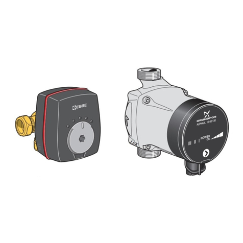
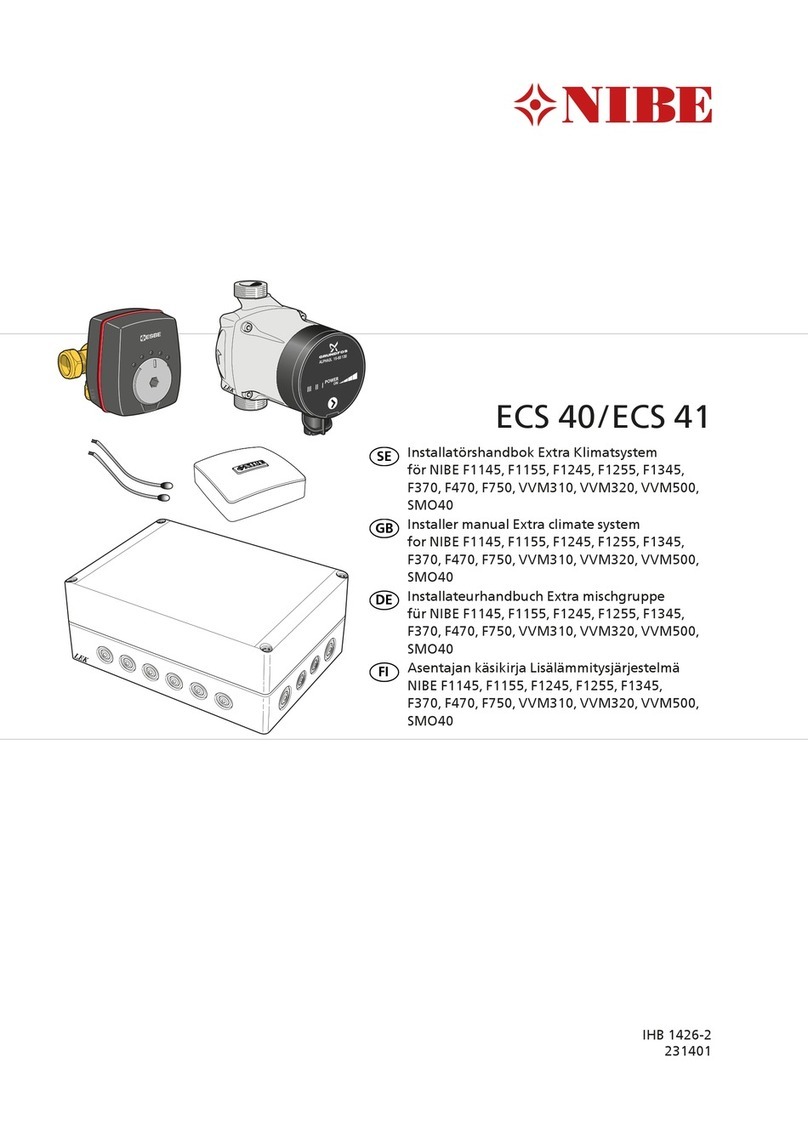
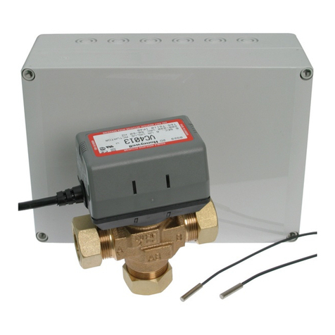
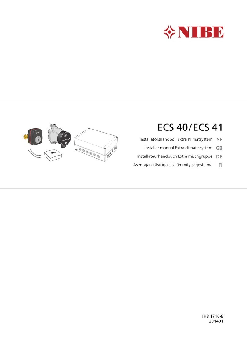
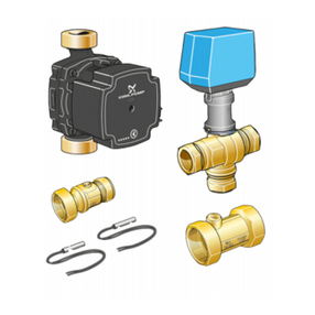
Nibe ECS 40 User guide

LEK
GRUN DFOS
Type UPS 25 - 60 130 P/N:59526447
230V-
HEJSAN
PC;0017NIB
DK
50Hz
IP 44
TF 110
Class H
Max. 10bar
2.5uF
45
0.20
65
0.30
900.40
1m(A) P,(W)
LEK
LEK
ECS 40/ECS 41
Installatörshandbok Extra Klimatsystem
SE
Installer manual Extra climate system
GB
Installateurhandbuch Extra mischgruppe
DE
IHB 1039-2
031431


Allmänt
Detta tillbehör används då F1145/F1245/F370/F470/F750
installeras i hus med upp till fyra olika klimatsystem som
kräver olika framledningstemperaturer, t.ex. då huset har
både radiatorsystem och golvvärmesystem.
Vattenflödet i klimatsystemen tillsammans bör inte över-
stiga 1700 l/h.
TÄNK PÅ!
Vid golvvärmesystem ska normalt max framled-
ningstemp. ställas in mellan 35 och 45 °C.
Kontrollera max temperatur för ditt golv med
din golvleverantör.
TÄNK PÅ!
Om rumsgivaren används i rum med med golv-
värme bör den endast ha visande funktion, inte
styrning av rumstemperatur.
Innehåll
Buntband4 st
Cirkulationspump1 st
Shuntmotor1 st
3-vägsventil1 st
Kit för tillbehörskort1 st
Värmeledningspasta2 st
Aluminiumtejp1 st
Isoleringstejp1 st
Utbytespackning2 st
Temperaturgivare2 st
Rumsgivare1 st
Rör med rak koppling*1 st
* Detta används endast vid inkoppling till NIBE F370 eller
F470.
Tekniska data
4140ECS
230 VManöverspänning
6,02,5KV-värde
22Anslutning ventil (Ø mm)
Komponentplacering
LEK
AA5-X4
AA5-S2
AA5-X2 AA5-X9 X1
FA1
AA5-F1AA5
Elkomponenter
AutomatsäkringFA1
Anslutningsplint, spänningsmatningX1
TillbehörskortAA5
Anslutningsplint, givare och extern blocke-
ring
AA5-X2
Anslutningsplint, kommunikationAA5-X4
Anslutningsplint, cirkulationspump, shunt
och hjälprelä
AA5-X9
DIP-switchAA5-S2
FinsäkringAA5-F1
Beteckningar i komponentplacering enligt standard IEC
81346-1 och 81346-2.
3
Svenska, Installatörshandbok - ECS 40/ECS 41
SE

Röranslutning
Allmänt
Vid anslutning av extra klimatsystem måste de kopplas
så att de har lägre arbetstemperatur är klimatsystem 1.
Cirkulationspump och shuntventil
Den extra cirkulationspumpen (GP20) placeras i det extra
klimatsystemet enligt principschema.
F1145/F1245/F750
႑Shuntventilen (QN25) placeras på framledningen efter
värmepumpen, före första radiator på klimatsystem
1. Returledningen från det extra klimatsystemet
kopplas till shuntventilen samt till returledningen från
värmesystem 1, se bild samt principschema.
F370/F470
႑Töm först pannvattenkärlet/värmesystemet om detta
är vattenfyllt.
႑Skruva bort den pluggade kopplingen som sitter på
dockningsanslutning (XL8).
႑Montera det medföljande plaströret med koppling i
dockningsanslutningen (XL8).
႑Shuntventilen (QN25) placeras på framledningen efter
värmepumpen från dess dockningsanslutning (XL8).
Returledningen från det extra klimatsystemet kopplas
till shuntventilen samt till returledningen från värme-
system 1, se bild samt principschema.
OBS!
Vid felaktig montering kan funktionen äventyras.
Shuntventil, (QN25)
Anslutningar, Ø 22 mm
LEK
LEK
Retur
Värmepump Framledning
Temperaturgivare
႑Framledningsgivaren (BT2) monteras på röret mellan
cirkulationspumpen (GP20) och shuntventil (QN11).
႑Returledningsgivaren (BT3) monteras på röret från
det extra klimatsystemet.
Temperaturgivarna monteras med buntband tillsammans
med värmeledningspasta och aluminiumtejp. Därefter
skall de isoleras med medföljande isolertejp.
OBS!
Givar- och kommunikationskablar får ej förläggas
i närheten av starkströmsledning.
4
SE

Pump- och tryckfallsdiagram, ECS 40
0
10
20
30
40
50
60
70
0 200 400 600 800 1000 1200 1400 1600
Flöde
kPa
l/h
l/s
0,40,30,20,10
Tillgängligt tryck
Flöde
Pump- och tryckfallsdiagram, ECS 41
Flöde
kPa
l/h
10
200
0
0
20
400
30
600
40
800
50
1000
60
1200
70
1400 1600 1800 2000
l/s
0,50,40,30,20,10
Max flöde:1700 l/h
Tillgängligt tryck Max flöde: 1700 l/h
Flöde
Principschemor
OBS!
Dessa är principscheman.
Verklig anläggning skall projekteras enligt gällan-
de normer.
Förklaring
VärmepumpEB100
Temperaturgivare, utomhusBT1
Temperaturgivare, varmvattenBT6
Nivåkärl, köldbärareCM2
Säkerhetsventil, köldbärareFL3
SmutsfilterHQ1
Klimatsystem 2EP21
TillbehörskortAA5
Framledningsgivare, extra klimatsystemBT2
Returledningsgivare, extra klimatsystemBT3
Cirkulationspump, extra klimatsystemGP20
Shuntventil, extra klimatsystemQN25
Klimatsystem 3EP22
Klimatsystem 4EP23
Övrigt
ExpansionskärlCM1
Ackumulatortank med varmvattenslingaCP1
KollektorEP12
Säkerhetsventil, värmebärareFL2
Påfyllningsventil, köldbärareQM12
Avstängningsventil, värmebärare framQM31
Avstängningsventil, värmebärare returQM32
Avstängningsventil, köldbärare returQM34
AvstängningsventilQM42
Påfyllnadsventilsats, köldbärareXL15
Beteckningar enligt standard IEC 81346-1 och 81346-2.
5
SE

Principschema F1145 med ECS 40/ECS 41 och upp till tre extra klimatsystem
-EB100-BT6
-CP1
-QM31
-FL2
-QM32
-FL3
-QM42
-QM12
-CM2
-EB100-HQ1
-CM1
-XL15
-EB100
F1145
-EB100
-EB100
-EB100-BT1
-QM34
-EP12
-GP20
-BT3
-BT2
-EP22
-QN25
-AA5
-GP20
-BT3
-BT2
-EP23
-QN25
-AA5
-BT3
-BT2
-EP21
-GP20
-QN25
-AA5
Principschema F1245 med ECS 40/ECS 41 och upp till tre extra klimatsystem
-FL3
-QM42
-QM12
-CM2
-EB100
-EB100
-QM34
-XL15
-EB100-BT1
-QM31
-QM32
-EB100-HQ1
F1245
-EB100
-FL2
-CM1
-EP12
-GP20
-BT3
-BT2
-EP22
-QN25
-AA5
-GP20
-BT3
-BT2
-EP23
-QN25
-AA5
-BT3
-BT2
-EP21
-GP20
-QN25
-AA5
6
SE

Principschema F370/F470 med ECS 40/ECS 41 och upp till tre extra klimatsystem
-EB100
-BT3
-BT2
-EP21
-GP20
-QN25
-AA5
-GP20
-BT3
-BT2
-EP22
-QN25
-AA5
-GP20
-BT3
-BT2
-EP23
-QN25
-AA5
7
SE

Principschema F750 med ECS 40/ECS 41 och upp till tre extra klimatsystem
-EB100
-BT3
-BT2
-EP21
-GP20
-QN25
-AA5
-GP20
-BT3
-BT2
-EP22
-QN25
-AA5
-GP20
-BT3
-BT2
-EP23
-QN25
-AA5
8
SE

Elinkoppling
OBS!
All elektrisk inkoppling skall ske av behörig
elektriker.
Elektrisk installation och ledningsdragning skall
utföras enligt gällande bestämmelser.
Värmepumpen ska vara spänningslös vid instal-
lation av ECS 40/ECS 41.
Elscheman finns i slutet av denna monteringsanvisning.
Anslutning av matning
Anslut spänningsmatningen till plint X1 enligt bild.
3
2
1N
230V 50Hz-X1
L
PE
$SSDUDWO§GD([WHUQWAnslutning av kommunikation
Detta tillbehör innehåller ett tillbehörskort (AA5) som ska
anslutas direkt till värmepumpen på ingångskortet (plint
AA3-X4).
Om flera tillbehör ska anslutas eller redan finns installerad
måste nedanstående instruktion följas.
Det första tillbehörskortet ska anslutas direkt till värme-
pumpens plint AA3-X4. De efterföljande korten anslutas
i serie med föregående kort.
Använd kabeltyp LiYY, EKKX eller likvärdig.
1
2
3
4
5
6
7
8
AA5-X4
15
A
B
GND
A
B
GND
A
B
GND
A
B
GND
A
B
GND
14
13
AA3-X4
1
2
3
4
5
6
7
8
AA5-X4
LEK
7LOOEHK¸UVNRUW7LOOEHK¸UVNRUW
ON
12345678
-X9
-X2
24 20212223 1516171819 1011121314 56789 1
1
N
L
PE
PE
1
2
3
4
5
6
7
8
2
3
4
5
6
7
8
9
234
-X8
-X4
-X10
-X1
$$;
ON
12345678
-X9
-X2
24 20212223 1516171819 1011121314 56789 1
1
N
L
PE
PE
1
2
3
4
5
6
7
8
2
3
4
5
6
7
8
9
234
-X8
-X4
-X10
-X1
$$;(%)))$$;$$;))$$;9
SE

Anslutning av givare
Använd kabeltyp LiYY, EKKX eller likvärdig.
Framledningsgivare, extra klimatsystem (BT2)
Anslut framledningsgivaren till AA5-X2:23-24.
Returledningsgivare, extra klimatsystem (BT3)
Anslut returledningsgivaren till AA5-X2:21-22.
Rumsgivare, extra klimatsystem (BT50) (valfritt)
Anslut rumsgivaren till AA5-X2:19-20.
%7$$;
24 20212223 16171819
%7%7
ON
12345678
-X9
-X2
24 20212223 1516171819 1011121314 56789 1
1
N
L
PE
PE
1
2
3
4
5
6
7
8
2
3
4
5
6
7
8
9
234
-X8
-X4
-X10
-X1
$$;TÄNK PÅ!
Reläutgångarna på tillbehörskortet får max be-
lastas med 2 A (230 V) totalt.
Anslutning av cirkulationspump (GP20)
Anslut cirkulationspumpen (GP20) till AA5-X9:8 (230 V),
AA5-X9:7 (N) och X1:3 (PE).
1
2
3
4
5
6
7
8
9
L
N
PE
3
2
1
(&6b(&6b([WHUQW;*3$$;
ON
12345678
-X9
-X2
24 20212223 1516171819 1011121314 56789 1
1
N
L
PE
PE
1
2
3
4
5
6
7
8
2
3
4
5
6
7
8
9
234
-X8
-X4
-X10
-X1
$$;Anslutning av shuntmotor (QN25)
Anslut shuntmotorn (QN25) till AA5-X9:6 (230 V, öppna),
AA5-X9:5 (N) och AA5-X9:4 (230 V, stäng).
1
2
3
4
5
6
7
8
9
(&6b(&6b([WHUQW$$;41%O§9LW%UXQ16W¦QJSSQD
ON
12345678
-X9
-X2
24 20212223 1516171819 1011121314 56789 1
1
N
L
PE
PE
1
2
3
4
5
6
7
8
2
3
4
5
6
7
8
9
234
-X8
-X4
-X10
-X1
$$;DIP-switch
DIP-switchen på tillbehörskortet ska ställas in enligt ne-
dan.
ON
12345678
-X9
-X2
24 20212223 1516171819 1011121314 56789 1
1
N
L
PE
PE
1
2
3
4
5
6
7
8
2
3
4
5
6
7
8
9
234
-X8
-X4
-X10
-X1
AA5-S2
Klimatsystem
432
ON
1 2 3 4 5 6 7 8
ON
1 2 3 4 5 6 7 8
ON
1 2 3 4 5 6 7 8
10
SE

Programinställningar
Programinställningen av ECS 40/ECS 41 kan göras via
startguiden eller direkt i menysystemet.
Startguiden
Startguiden visas vid första uppstart efter värmepumpsin-
stallationen, men finns även i meny 5.7.
Menysystemet
Om du inte gör alla inställningar via startguiden eller be-
höver ändra någon inställning kan du göra detta i meny-
systemet.
Meny 5.2 - systeminställningar
Aktivering/avaktivering av tillbehör.
Välj: "klimatsystem 2" för klimatsystem 2, "klimatsystem
3" för klimatsystem 3 samt "klimatsystem 4" för klimat-
system 4.
Meny 5.1.2 - max framledningstemp.
Inställning av högsta framledningstemperatur till varje
klimatsystem.
Meny 5.3.3 - extra klimatsystem
Shuntinställningar för extra installerade klimatsystem.
Meny 1.1 - temperatur
Inställning av inomhustemperatur.
Meny 1.9.1 - värmekurva
Inställning av värmekurva.
Meny 1.9.2 - extern justering
Inställning av extern justering.
Meny 1.9.3 - min. framledningstemp.
Inställning av lägsta framledningstemperatur till varje kli-
matsystem.
Meny 1.9.4 - rumsgivarinställningar
Aktivering och inställning av rumsgivare.
Meny 5.6 - tvångsstyrning
Tvångsstyrning av de olika komponenterna i värmepum-
pen samt i de olika tillbehören som eventuellt är anslutna.
EP21 är klimatsystem 2, EP22 är klimatsystem 3, EP23 är
klimatsystem 4.
EP2#-AA5-K1: Ingen funktion.
EP2#-AA5-K2: Signal (stäng) till shunt (QN25).
EP2#-AA5-K3: Signal (öppna) till shunt (QN25).
EP2#-AA5-K4: Aktivering av cirkulationspump (GP20).
TÄNK PÅ!
Se även Installatörshandboken för respektive
värmepump.
11
SE

12
SE

General
This accessory is used when F1145/F1245/F370/F470/F750
is installed in houses with up to four different climate
systems that require different flow line temperatures, for
example, in cases where the house has both a radiator
system and an under floor heating system.
The water flow in the climate systems together should
not exceed 1700 l/h.
Caution
Underfloor heating systems are normally max
flow line temperature set between 35 and 45
°C.
Check the max temperature for your floor with
your floor supplier.
Caution
If the room sensor is used in a room with under
floor heating it should only have an indicatory
function, not control of the room temperature.
Contents
Cable ties4 x
Circulation pump1 x
Shunt motor1 x
3-way valve1 x
Kit for accessory card1 x
Heating pipe paste2 x
Aluminium tape1 x
Insulation tape1 x
Replacement gasket2 x
Temperature sensor2 x
Room sensor1 x
Pipe with straight coupling*1 x
* This is only used when connecting to NIBE F370 or
F470.
Technical specifications
4140ECS
230 VControl voltage
6,02,5KV value
22Connection valve (Ø mm)
Component positions
LEK
AA5-X4
AA5-S2
AA5-X2 AA5-X9 X1
FA1
AA5-F1AA5
Electrical components
Miniature circuit-breakerFA1
Terminal block, power supplyX1
Accessory cardAA5
Terminal block, sensors and external
blocking
AA5-X2
Terminal block, communicationAA5-X4
Terminal block, circulation pump, mixing
valve and auxiliary relay
AA5-X9
DIP switchAA5-S2
Fine-wire fuseAA5-F1
Designations in component locations according to
standard IEC 81346-1 and 81346-2.
13
English, Installer manual - ECS 40/ECS 41
GB

Pipe connections
General
When connecting extra climate systems, they must be
connected so that they have a lower working temperature
than the climate system 1.
Circulation pump and mixing valve
The extra circulation pump (GP20) is positioned in the
extra climate system according to the outline diagram.
F1145/F1245/F750
႑The mixing valve (QN25) is located on the flow line
after the heat pump, before the first radiator in the
climate system 1. The return line from the extra cli-
mate system is connected to the mixing valve and to
the return line from the heating system 1, see image
and outline diagram.
F370/F470
႑First drain the boiler water reservoir/heating system
if filled with water.
႑Unscrew the plugged connection that is on the
docking connection (XL8).
႑Install the supplied plastic pipe with coupling in the
docking connection (XL8).
႑The mixing valve (QN25) is located on the flow line
after the heat pump from its docking connection
(XL8). The return line from the extra climate system
is connected to the mixing valve and to the return
line from the heating system 1, see image and outline
diagram.
NOTE
Incorrect installation can affect the function.
By-pass valve, (QN25)
Connections, Ø 22 mm
LEK
LEK
Return
Heat pump Flow pipe
Temperature sensor
႑The flow temperature sensor (BT2) is installed on the
pipe between the circulation pump (GP20) and mixing
valve (QN11).
႑The return line sensor (BT3) is installed on the pipe
from the extra climate system.
Install the temperature sensors with cable ties with the
heat conducting paste and aluminium tape. Then insulate
with supplied insulation tape.
NOTE
Sensor and communication cables must not be
placed near power cables.
14
GB

Pump and pressure drop diagrams, ECS 40
0
10
20
30
40
50
60
70
0 200 400 600 800 1000 1200 1400 1600
Flöde
kPa
l/h
l/s
0,40,30,20,10
Available pressure
Flow
Pump and pressure drop diagrams, ECS 41
Flöde
kPa
l/h
10
200
0
0
20
400
30
600
40
800
50
1000
60
1200
70
1400 1600 1800 2000
l/s
0,50,40,30,20,10
Max flöde:1700 l/h
Available pressure Max flow: 1700 l/h
Flow
Outline diagrams
NOTE
These are outline diagrams.
Actual installations must be planned according
to applicable standards.
Explanation
Heat pumpEB100
Temperature sensor, outdoorBT1
Temperature sensor, hot waterBT6
Level vessel, brineCM2
Safety valve, brineFL3
Particle filterHQ1
Climate system 2EP21
Accessory cardAA5
Flow temperature sensor, extra climate sy-
stem
BT2
Return line sensor, extra climate systemBT3
Circulation pump, extra climate systemGP20
Mixing valve, extra climate systemQN25
Climate system 3EP22
Climate system 4EP23
Miscellane-
ous
Expansion vesselCM1
Accumulator tank with hot water coilCP1
CollectorEP12
Safety valve, heating mediumFL2
Filler valve, brineQM12
Shut-off valve, heating medium flowQM31
Shut off valve, heating medium returnQM32
Shut off valve, brine returnQM34
Shut-off valveQM42
Filling set, brineXL15
Designations according to standards 81346-1 and 81346-
2.
15
GB

Outline diagram F1145 with ECS 40/ECS 41 and up to three extra climate systems
-EB100-BT6
-CP1
-QM31
-FL2
-QM32
-FL3
-QM42
-QM12
-CM2
-EB100-HQ1
-CM1
-XL15
-EB100
F1145
-EB100
-EB100
-EB100-BT1
-QM34
-EP12
-GP20
-BT3
-BT2
-EP22
-QN25
-AA5
-GP20
-BT3
-BT2
-EP23
-QN25
-AA5
-BT3
-BT2
-EP21
-GP20
-QN25
-AA5
Outline diagram F1245 with ECS 40/ECS 41 and up to three extra climate systems
-FL3
-QM42
-QM12
-CM2
-EB100
-EB100
-QM34
-XL15
-EB100-BT1
-QM31
-QM32
-EB100-HQ1
F1245
-EB100
-FL2
-CM1
-EP12
-GP20
-BT3
-BT2
-EP22
-QN25
-AA5
-GP20
-BT3
-BT2
-EP23
-QN25
-AA5
-BT3
-BT2
-EP21
-GP20
-QN25
-AA5
16
GB

Outline diagram F370/F470 with ECS 40/ECS 41 and up to three extra climate systems
-EB100
-BT3
-BT2
-EP21
-GP20
-QN25
-AA5
-GP20
-BT3
-BT2
-EP22
-QN25
-AA5
-GP20
-BT3
-BT2
-EP23
-QN25
-AA5
17
GB

Outline diagram F750 with ECS 40/ECS 41 and up to three extra climate systems
-EB100
-BT3
-BT2
-EP21
-GP20
-QN25
-AA5
-GP20
-BT3
-BT2
-EP22
-QN25
-AA5
-GP20
-BT3
-BT2
-EP23
-QN25
-AA5
18
GB

Electrical connection
NOTE
All electrical connections must be carried out by
an authorised electrician.
Electrical installation and wiring must be carried
out in accordance with the stipulations in force.
The heat pump must not be powered when in-
stalling ECS 40/ECS 41.
The electrical circuit diagram is at the end of these install-
ation instructions.
Connecting the supply
Connect the power supply to terminal block X1 as illus-
trated.
3
2
1N
230V 50Hz-X1
L
PE
8QLWER[([WHUQDOConnecting communication
This accessory contains an accessories card (AA5) that
must be connected directly to the heat pump on the input
card (terminal block AA3-X4).
If several accessories are to be connected or are already
installed, the following instructions must be followed.
The first accessory card must be connected directly to the
heat pump's terminal block AA3-X4. The following cards
must be connected in series with the previous card.
Use cable type LiYY, EKKX or similar.
1
2
3
4
5
6
7
8
AA5-X4
15
A
B
GND
A
B
GND
A
B
GND
A
B
GND
A
B
GND
14
13
AA3-X4
1
2
3
4
5
6
7
8
AA5-X4
LEK
$FFHVVRU\FDUG$FFHVVRU\FDUG
ON
12345678
-X9
-X2
24 20212223 1516171819 1011121314 56789 1
1
N
L
PE
PE
1
2
3
4
5
6
7
8
2
3
4
5
6
7
8
9
234
-X8
-X4
-X10
-X1
$$;
ON
12345678
-X9
-X2
24 20212223 1516171819 1011121314 56789 1
1
N
L
PE
PE
1
2
3
4
5
6
7
8
2
3
4
5
6
7
8
9
234
-X8
-X4
-X10
-X1
$$;(%)))$$;$$;))$$;19
GB

Connecting sensors
Use cable type LiYY, EKKX or similar.
Flow temperature sensor, extra climate system
(BT2)
Connect the flow temperature sensor to AA5-X2:23-24.
Return line sensor, extra climate system (BT3)
Connect the return line sensor to AA5-X2:21-22.
Room temperature sensor, extra climate system
(BT50) (optional)
Connect the room temperature sensor to AA5-X2:19-20.
%7$$;
24 20212223 16171819
%7%7
ON
12345678
-X9
-X2
24 20212223 1516171819 1011121314 56789 1
1
N
L
PE
PE
1
2
3
4
5
6
7
8
2
3
4
5
6
7
8
9
234
-X8
-X4
-X10
-X1
$$;Caution
The relay outputs on the accessory card can have
a max load of 2 A (230 V) in total.
Connection of the circulation pump (GP20)
Connect the circulation pump (GP20) to AA5-X9:8 (230
V), AA5-X9:7 (N) and X1:3 (PE).
1
2
3
4
5
6
7
8
9
L
N
PE
3
2
1
(&6b(&6b([WHUQDO;*3$$;
ON
12345678
-X9
-X2
24 20212223 1516171819 1011121314 56789 1
1
N
L
PE
PE
1
2
3
4
5
6
7
8
2
3
4
5
6
7
8
9
234
-X8
-X4
-X10
-X1
$$;Connection of the mixing valve motor (QN25)
Connect the mixing valve motor (QN25) to AA5-X9:6
(230 V, open), AA5-X9:5 (N) and AA5-X9:4 (230 V, close).
1
2
3
4
5
6
7
8
9
(&6b(&6b([WHUQDO$$;41%OXH:KLWH%URZQ1&ORVH2SHQ
ON
12345678
-X9
-X2
24 20212223 1516171819 1011121314 56789 1
1
N
L
PE
PE
1
2
3
4
5
6
7
8
2
3
4
5
6
7
8
9
234
-X8
-X4
-X10
-X1
$$;DIP switch
The DIP switch on the accessory card must be set as fol-
lows.
ON
12345678
-X9
-X2
24 20212223 1516171819 1011121314 56789 1
1
N
L
PE
PE
1
2
3
4
5
6
7
8
2
3
4
5
6
7
8
9
234
-X8
-X4
-X10
-X1
AA5-S2
Climate system
432
ON
1 2 3 4 5 6 7 8
ON
1 2 3 4 5 6 7 8
ON
1 2 3 4 5 6 7 8
20
GB
Other manuals for ECS 40
8
This manual suits for next models
1
Table of contents
Languages:
Other Nibe Temperature Controllers manuals
Popular Temperature Controllers manuals by other brands

DOTECH
DOTECH TX3 Series operating instructions

Ropex
Ropex RESISTRON RES-5027 operating instructions

Gemo
Gemo LT102HT quick start guide

Carbolite
Carbolite 201 operating instructions

REGLOPLAS
REGLOPLAS 300L operating instructions

Viessmann
Viessmann VITOSOLIC 100 Installation and service instructions for contractors