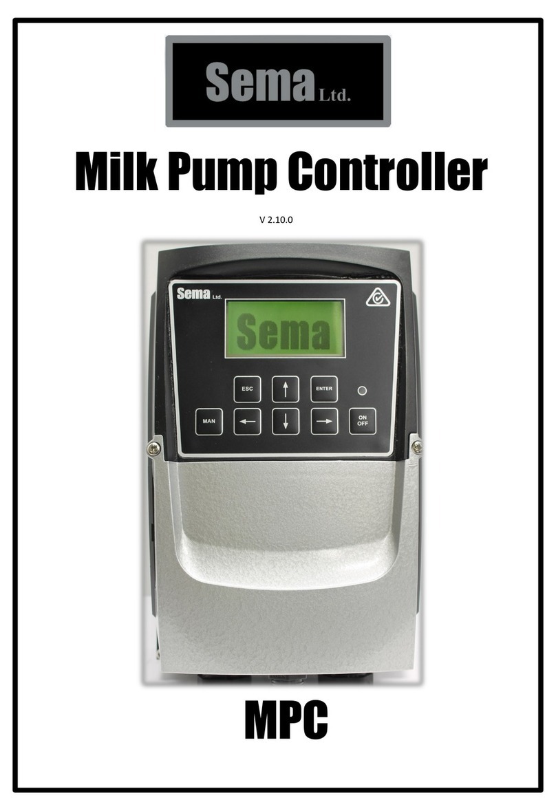
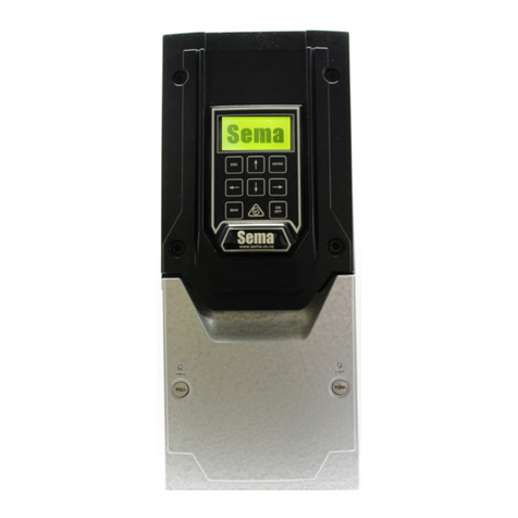
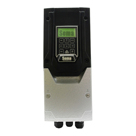
sema EPCP3-11Plus Mk2 User manual

V 2.6.1
EPCP3-11Plus Mk2 User Manual
For Mk2 Effluent Pump Pressure Controllers 11Kw and above.

2
This manual applies to all Sema Euent Pump Controllers above 7.5Kw that operate by
controlling the euent pressure.
Sema Part Numbers
EPCP3-11 11 Kw 400 Vac three phase controller c/w transducer
EPCP3-15 15 Kw 400 Vac three phase controller c/w transducer
EPCP3-22 22 Kw 400 Vac three phase controller c/w transducer
EPCP3-37 37 Kw 400 Vac three phase controller c/w transducer
The four sizes listed above are ex -stock. Larger sizes are ordered to suit. There are
three delivery opons with the larger sizes 5 week (standard) 3 week and 1 week.
The part numbers for larger sized controllers are EPCP3– followed by the size of the
drive in Kw. E.g. EPCP3-45
Contact details
Sema Ltd
P.O. Box 374 Pukekohe 2340 New Zealand
5c Tregoweth Lane, Huntly 3700, New Zealand
www.sema.co.nz
info@sema.co.nz
+64 9 3580800 Oce, Tech support and Admin 24/7
+64 9 3580700 Workshop 9 to 5 Monday to Friday
Fax +64 9 8010031
Contact Maurice Coates on +64 27 9396240
maurice.coates@sema.co.nz

3
Index
Sema Part Numbers & Contact Details 2
Installaon Instrucons 4
Wiring 5-8
Emergency Mode 7
The Keypad 9
Inial Set-Up 10-11
The Running Screen 12
Changing Parameters 12-14
Faults 15
Supplier Declaraon of Conformity 16
Invertek drives manuals and declaraons of conformity 17
Please read the important informaon below:
Thanks very much for purchasing one of our euent pump controllers. This controller has
been designed and engineered to be as robust and reliable as a device of this kind can
be. Please note though that this is an electronic device and so, by its very nature, is not
failsafe. While the Maximum Run Time, Loss of Prime, Blocked Pipe and Burst pipe pro-
tecons are generally extremely reliable and eecve they should not be relied upon as
the sole source of protecon against equipment damage or environmental contamina-
on.
These controllers have an IP rang of 55 which means that they do not need to be in-
stalled in a cabinet. Please note, however, that they are not U.V. proof and must be pro-
tected from exposure to direct sunlight. Note also that, as rainwater can be extremely
acidic, they should be protected against constant exposure to rain.
If installing one of these units in a cabinet please ensure that the cabinet has sucient
fan forced venlaon to limit its temperature rise to a maximum of 2 degrees Celsius
above the ambient air temperature

4
Installing
Mounng
The 11, 15 and 22Kw drives share the same dimensions:
Please ask Sema for details on the larger units:
The controller must be mounted vercally with sucient clearance above and below the drive to allow air to circulate freely.
The operang temperature range is –10 °C to 40°C.
If installing this unit in a cabinet ensure that enough fan forced venlaon is
installed to limit the temperature rise in the cabinet to no more than 2 de-
grees above the ambient air temperature.
High temperatures drascally reduce the life expectancy of all electronic devices. The cooler that you can keep your EPC the
longer it will last.
Front Rear Side
110mm
171mm
430mm
8.00mm
14.00mm
450mm
252mm

5
Wiring
All wiring must be performed by a suitably qualified person who is familiar with, and ensures compliance
with, the appropriate Electrical Wiring Regulations.
There is no need to use screened mains cabling.
EMC screened cable must be used to connect the controller and motor. An EMC gland must be fitted to
the motor and the preinstalled EMC Gland must be used in the controller.
All wiring that exits the controller including low voltage control cabling must be screened.
The picture above shows the control terminals of the EPCP. The terminals are numbered from 1 to 28 and
their functions are shown on page 8. The wiring and links shown in the picture are installed by Sema and
are necessary for the correct functioning of the controller. Please do not remove or alter any of these.
While there are other optional components
which may be wired to these terminals (see
page 8) the only additional piece of wiring
which is essential to make the unit operate is
from the transducer. Connect this as follows:
RED wire to terminal 1.
BLACK (in some cables this may be blue) wire
to terminal 6.
Green/Yellow striped (in some cables this may
have a clear covering) wire to terminal 7 or 9

6
Three Glands are ed to the boom of the VSD.
25mm Gland
for the Main
supply cable
‘25mm gland for
the motor cable.
This gland has a
‘brushed locknut’
ed. To termi-
nate the screen
on the motor ca-
ble simply bare 10
to 15mm of the
screen and push it
through the
brushed locknut.
20mm Gland for the
Transducer cable, the
controller communica-
on cable and the op-
onal control cable
The motor gland has a brushed locknut ed to it (see below). Somemes well intenoned installers remove this gland and
locknut and replace it with an EMC gland. Please note that the brushed locknut has an equal or greater performance to an
EMC gland and that there is nothing to be gained by replacing it. To terminate the screen of the motor cable to the brushed
locknut simply strip back enough of the plasc sheath so that the screen can contact the brush before inserng the cable
through the gland. This will make an extremely eecve EMC earthing connecon and also maintain the units waterproong
rang through the use of an IP68 gland.

7
Power and Motor Connecons
To reverse the direcon of rotaon of the motor change over any two of the three motor
wires (U,V and W)
Connect the main
supply wires to
L1, L2 and L3
Connect the mo-
tor wires to U, V
and W
Connect the
earth wires to
the earth screws
Emergency Mode: If the Transducer fails the EPCP will stop. This is done to prevent possible over pres-
surising of the system. Because a Transducer isn’t a device which is readily available in all parts of the world an
Emergency Mode has been provided to enable the unit to run from a pressure switch.
To acvate Emergency Mode:
1. Turn o the power and wait unl the screen is dark .
2. Connect a Pressure Switch between terminals 1 & 2 (It doesn’t maer whether you leave the pre-installed
white wire in terminal 2 or not.)
3. Turn on the power and the unit will now detect the Pressure Switch, it will respond by acvang its emergen-
cy mode and act as an on/o controller in response to the input from the pressure switch.

8
Terminal
Number
Signal Control Terminal Descripon
1+24VDC The RED wire from the transducer should be connected here or to terminal 21
2Controller The white wire from the controller communicaons cable is connected here
3Remote Run As supplied by Sema there is a link between terminals 1 and 3. A remote stop
switch may be connected in place of this.
4No user connecon
5No user connecon
64 to 20 ma analogue The BLACK (In some cables this may be Blue) transducer wire is connected here
70V The CLEAR (In some cables this may be a green and yellow stripe) transducer
wire is connected here. This is the screen.
8Analogue Output The analogue output puts out a 0 to 10VDC signal. It is programmable in funcon
10
90V
10 No User connecon
11 No User connecon
12 No User connecon
13 No User connecon
14 Relay 1 Common
15 Relay 1 N.O. Relay 1 turns on when the controller has a fault
16 Relay 1 N.C
17 Relay 2 Common Relay 2 turns on when the unit is running
18 Relay 2 N.O.
19 No User connecon
20 0V
21 +24VDC The commons for the Oponal remote pressure select switches should be con-
nected here or to terminal 1.
22 0V
23 Priming Solenoid Output A priming solenoid may be connected between here and any 0V terminal
24 No User connecon
25 No User connecon
26 No User connecon
27 Setpoint 2 Switch The switch that selects setpoint 2 should be connected here.
28 Setpoint 3 Switch The switch that selects setpoint 3 should be connected here.

9
Seng up and Operaon
Using the keypad
Descripon:
ESC The escape key funcons in the same manner as the escape key on a computer it allows you to exit without sav-
ing parameters and also allows you to go back a step when going through the inial setup roune.
UP ARROW Increases the digit immediately above the cursor when entering parameter values and scrolls
through a menu list.
ENTER Accepts and saves a value which has been entered. Press and hold for 3 seconds to access the Funcon
menu from the main running screen.
MAN Short for Manual this will run the pump manually for as long as it is pressed. It will also put the controller in
‘Emergency’ mode if it is held down when the power is turned on.
LEFT ARROW Moves the cursor one posion to the le when entering parameter values.
DOWN ARROW Decreases the digit immediately above the cursor when entering parameter values and scrolls
through a menu list.
RIGHT ARROW Moves the cursor one posion to the Right when entering parameter values.
ON OFF Press once to turn the controller o, press again to turn the controller on.
Hint: When entering numbers use the le and right arrow keys to move the cursor and the up and down arrow keys to
change the number above the cursor.

10
Inial Set Up
A few seconds aer powering the unit up for the rst me, or aer re-inialising it, the screen below will be displayed.
The only valid key which can be pressed is the ENTER key and the only way of stopping this screen from appearing is to com-
plete the setup roune.
Please note that, if you make a mistake and enter the wrong value in one of the steps, the ESC key can be used to go back a
step. You can go back as many steps as you like even right to the start of the setup roune if necessary.
The sengs that you enter are only saved aer you complete the last step so, providing you haven’t completed the nal step,
you can always start setup again by turning o the power and then powering up again.
The controller can also be re-inialised. See the ’Changing Parameters’ secon for instrucons on how to do this.
There are 16 steps in the setup roune and they are as follows:-
1. ENTER THE MOTORS NAMEPLATE VOLTAGE: Use the arrow keys to alter the value.
2. ENTER THE MOTORS NAMEPLATE CURRENT: Use the arrow keys to alter the value.
3. ENTER THE MOTORS NAMEPLATE RPM: Use the arrow keys to alter the value.
4. ENTER THE MOTORS MAXIMUM SPEED: Here you can enter the maximum operang RPM of the
motor. This gure may be adjusted up to double the motors rated nameplate RPM but please note that very few pumps can be
operated at this sort of speed. If you are in doubt about the maximum speed that your pump can be operated at then please
set this gure to the same value as the Motors Rated Nameplate speed. Note that this is the value that appears by default.
5. ENTER THE MOTORS MINIMUM SPEED: This gure is also determined by the minimum speed that
your pump can successfully run at. If you are in doubt then the default gure can safely be used.
6. MOTOR DIRECTION CHECK: Pressing the up arrow will cause the motor to run at low speed for a couple of
seconds so that you can check that the direcon of rotaon is correct. If it isn’t then turn o the power and, aer the control-
ler screen goes completely dark, remove the controller terminal cover and swap any two wires connected to U,V and W. Once
this is done turn the power on again and you will be bought back to this step, all of your previous programming will have been
saved. Conrm that the direcon is now correct and then press ENTER to connue.

11
7. First Set-Point. Enter the pressure (in Bar) that you would like the system to operate at when the inputs connected
to terminals 27 and 28 are OFF.
8. Second Set-Point. Enter the pressure (in Bar) that you would like the system to operate at when the input con-
nected to terminal 27 is ON.
9. Third Set-Point. Enter the pressure (in Bar) that you would like the system to operate at when the input connected
to terminal 27 is ON.
10. ENTER THE MAXIMUM ALLOWED RUN TIME. Enter the maximum me (in HOURS) that the
controller is allowed to run connuously for before it will shut down and display an error. Seng this to 0 disables this func-
on.
11. LoP (Loss of Prime). This step is for checking the current that the motor draws when the pump is not pumping
water, you can run the pump by pressing and holding the MAN key. This gure can then be used in the next step as the Loss of
Prime level for the motor . To obtain this gure either run the pump empty or block o its outlet so that it is not pumping wa-
ter. Note that, if the feed to the pressure vessel cannot be shut o, then the pump must be run unl the pressure vessel is
completely up to pressure. You will be able to tell when this has happened as the motor current will stop reducing.
12. LoP Current Level. Enter the gure that was obtained in step 11. To turn o the LoP funcon set this gure to
zero.
13. Burst Pipe Detecon. The controller uses its own built in logic to determine if a pipe has burst. This funcon
may be enabled or disabled here. Please note that burst pipe detecon is an aid only, it is not failsafe and should not be re-
lied upon as the sole means of burst pipe detecon.
14. Maximum Pressure. If this pressure is exceeded the unit will shut down and display a blocked pipe fault. This
seng can be used if the travelling spreader has a shut o valve which operates at the end of its travel.
15. Fill Pipe Delay. This supresses most faults and keeps the pump at minimum speed for the number of minutes en-
tered to allow the system to start and ll the pipes.
16. Fill Pipe Speed. During the “Fill Pipe Delay” the speed that the controller runs at can me set at either Minimum or
Automac (default). Automac means that the controller will sll control pressure during the ll pipe delay as opposed to just
running the pump at its minimum speed.
17. Startup Delay. This delays the start of the pump for the number of seconds entered to allow a srrer and/or prim-
ing solenoid to operate before the pump starts. Note that if an oponal priming solenoid is connected to output 23 it will con-
nue to operate unl the pump reaches the setpoint pressure.
This completes setup, the controller is now fully congured and customised for this installaon Please read the following
secons which describe the running screen and how to alter parameters on a controller which has already been congured.

12
Running
The Running Screen:
Mode
Motor RPM
Motor Current
MODE Six dierent modes may be displayed here:
1. STOPPED If the on/o buon is pressed this will be displayed.
2. RUNNING When the pump is running this will be displayed followed by a me showing how long it has been running
for.
3. READY TO RUN If the pressure is above the setpoint when the unit is powered up ready to run will be displayed as an
indicaon that the unit will start as soon as the pressure drops.
4. MANUAL When the “Man” buon is pressed on the keypad this is displayed and the unit will ramp up to full speed.
5. EMERGENCY MODE Indicates that the unit is operang in emergency mode (See page 7)
6. REMOTE STOP Indicates that the remote run input on terminal 3 is o
Changing Parameters:
To access the parameters (also called funcons) menu press and HOLD the
ENTER key for between 2 and 3 seconds. (A screen will be displayed telling
you to remove your nger aer this me)
SetPoint
Actual Pressure

13
Non Password Protected Parameters:
0.) Password Enter the password here which unlocks the protected parameters (11 to 19) The password is
00004
1.) Minimum Speed The minimum speed of the pump can be adjusted here.
2.) Maximum Speed The maximum speed of the pump can be adjusted here.
3.) Setpoint 1 This is the pressure set-point when inputs 27 & 28 are OFF
4.) Setpoint 2 Tis is the pressure set-point when the input 27 is ON
5.) Setpoint 3 Tis is the pressure set-point when the input 28 is ON
6.) Maximum Run Time. This is the me in hours that the pump is permied to run connuously for. If it is ex-
ceeded the pump will be stopped and an error message displayed. Set it to 0 to disable this funcon.
Password Protected Parameters:
Once the password has been entered correctly in Parameter 0 the password protected funcons 9 to 19 become visible.
Some of them require the pump to be stopped before they can be adjusted, if you try to adjust one of these with the pump
running you will be asked to stop it before proceeding
Leaving the parameter menu resets the password.
7.) Fill Pipe Speed During the “Fill Pipe Delay” the speed that the controller runs at can me set at either Minimum or
Automac (default). Automac means that the controller will sll control pressure during the ll pipe delay as opposed to just
running the pump at its minimum speed.
8.) Burst Pipe Delay When the controller is running at full speed but not achieving its set pressure a “Burst Pipe”
fault will be generated aer the period of me entered here. The valid range is 0 to 300 seconds. The default is 60 seconds.
9.) START DELAY. This delays the start of the pump for the number of seconds that is entered. This is to allow a srrer
and/or a priming solenoid to operate before the pump starts
10.) ANALOGUE OUTPUT CONFIGURATION. The controller can be programmed to output a 0 to
10VDC on terminal 8. This signal can be set to give a proporonal output to one of the following.
A.) Motor Speed (0 to 100%)
B.) Motor Current (0 to 200% of the motors nameplate current. i.e. 5 volts would equal the motors nameplate current)
C.) Motor Torque (0 to 200%)
D.) Motor Power (0 to 200%)
11.) BURST PIPE DETECTION. The controller uses its own built in logic to determine if a pipe has burst. This
funcon may be enabled or disabled here. Please note that burst pipe detecon is an aid only, it is not failsafe and should
not be relied upon as the sole means of burst pipe detecon.

14
12.) MAX PRESSURE. For constant displacement pumps the pressure that must not be exceeded can be entered
here.
13.) Fill Pipe Delay. This supresses most faults and keeps the pump at minimum speed for the number of minutes
entered to allow the system to start and ll the pipes.
14.) Control Method. By default this is set to ‘Convenonal’. Ripple control is a Sema Ltd., invenon which intro-
duces a small pressure ripple into the pressure set-point and measures the me that it takes for the pressure to drop to deter-
mine is there is sucient ow for the pump to be kept running. If you would like to operate the pump in Ripple control mode
(with the ripple) then change this mode to ‘Ripple Control’.
15.) Pressure Averaging. By default the EPC performs a rolling average of mulple readings from the pressure
transducer over a 2 second period to determine the eluent pressure. This is to make the reading more stable and reduce the
inuence of air bubbles in the euent stream. If this is considered undesirable it can be turned o here.
16.) Control Loop Delay. The EPC waits for this length of me aer starng before it tries to control the pressure.
This is to give it a few seconds of ‘seling me’ at minimum speed. This me may be adjusted here or even set to 0 if this is
considered desirable.
17.) Lop (Loss of Prime) Current. This is set to the current that the motor draws when the pump is not
pumping (i.e. when it is running dry) If the motor current is at or below this gure for more than 10 seconds the pump will be
stopped and an error message displayed.
18.) Motor Current Adjust the motor current here if necessary to avoid nuisance tripping.
19.) Re-Inialise If the controller is moved to a new pump shed or a new pump is installed on the same controller
then the controller should be re-inialised and the setup roune re done. Follow the prompts on the screen to achieve this.

15
FAULTS
If a fault occurs that stops the controller running the backlight on the screen will flash rapidly and the fault description and
fault number will be displayed. Please write down this number as it will provide Sema Ltd., with important information about
the cause of the fault.
If a fault occurs turn off the power, wait until the controller screen is completely dark and then turn the power back on again. If
the fault is still present then contact your Dealer or Sema Ltd.
Possible Faults:
Short Circuit. Check the motor cable and the motor for electrical faults
Motor Overloaded. Check that the pump isn’t jammed. Attempt a reset by turning the power off and back on
again. When the motor starts observe its running current (middle figure on the main running screen) and ensure that it is less
than the nameplate current.
Over Voltage. Contact your power company. This will damage the controller it it’s allowed to continue.
Under Voltage. The controller cannot run because there is insufficient power. Contact your power company.
Too Hot. The controller is overheated. Check that the cooling fins are not blocked and that the air temperature is not
above 40 degrees Celsius.
Too Cold. The controller must be above –10 degrees Celsius before it will start. If the air temperature is less that this then
gently warm the controller until it is able to start, once it has started it should generate enough internal heat to keep running.
Maximum Run Time Exceeded. The pump has run continuously for more than the maximum allowed run
time. Usually this is caused by a water leak. Pushing the on/off button restarts the pump and resets the timer.
LoP (Loss of Prime or Pump Running Dry). Make sure that the pump has effluent available. Press the
On/Off button to restart the pump.
BURST PIPE DETECTED. The pressure full below the level set in Function 11.
PIPE BLOCKED. The controller has detected a lack of flow most probably caused by a blocked pipe.
Transducer Fault. Either the Transducer is faulty or there is a fault in the Transducer wiring (Might pay to check the
plug on the transducer to make sure that it’s properly plugged in!). If you can’t rectify the problem then you can run the con-
troller in ‘Emergency Mode’ from a pressure switch. See below:
Emergency Mode: If the Transducer fails the WPC will stop. This is done to prevent possible over pressurising of the
system. Because a Transducer isn’t a device which is readily available in all parts of the world an Emergency Mode
has been provided to enable the unit to run from a pressure switch.
To activate Emergency Mode:
1. 1. Turn off the power and wait until the screen is dark .
2. 2. Connect a Pressure Switch between terminals 1 & 2 (It doesn’t matter whether you leave the pre-installed
white wire in terminal 2 or not.)
3. 3. Turn on the power and the unit will now detect the Pressure Switch, it will respond by activating its emer-
gency mode and act as an on/off controller in response to the input from the pressure switch.

16

17
EMC Compliance
The current range of Sema product is based on the Invertek Drives range of variable speed drives. Units
of 7.5kw and below use the E3 series of drives and units above 7.5kw use the P2 series.
Manuals and compliance information for these drives can be found at www.sema.co.nz or scan the QR
codes below to be taken straight to the relevant document.
For information on how to perform a CE EMC compliant installation please view or download the
appropriate Invertek manual and look in its index for the page labelled “EMC Compliant Installation”.
Invertek E3 Conformity Certificate
Invertek E3 Manual
Invertek P2 Conformity Certificate
Invertek P2 Manual
This manual suits for next models
5
Table of contents
Other sema Controllers manuals
Popular Controllers manuals by other brands
Zennio
Zennio ZIO-IB24 user manual
Model Train Technology
Model Train Technology G-Controller Operation manual
PS Automation
PS Automation PS-AMS Series operating instructions
Fujitsu
Fujitsu UTY-TERX installation manual
rotork
rotork IQT Series Installation and maintenance instructions
Njoy
Njoy Paladin 1000 user manual
Norac
Norac UC5 Topcon X30 installation manual

Supero
Supero Supero SMT IPMI user guide
Emerson
Emerson unidrive m200 Parameter reference guide
Newport
Newport iDRA Controller DIN Rail Temperature/Process with Isolated Analog Output... Operator's manual

Eaton
Eaton Vickers SMC20 Product support

SOMFY
SOMFY animeo IB + 1860049 installation guide
