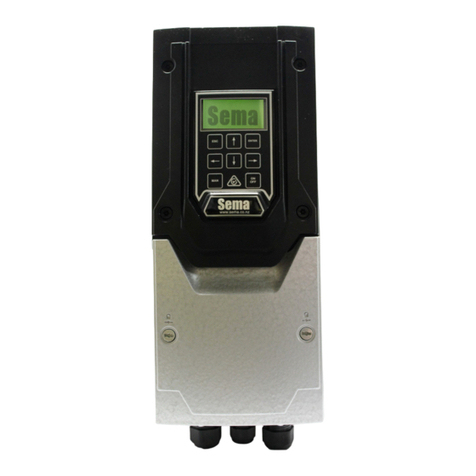
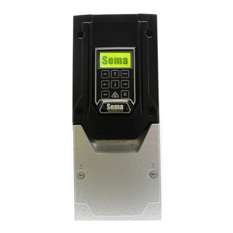
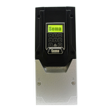
sema MPC Series User manual

Milk Pump Controller
V 2.10.0
MPC

2
-
-
Sema Part Numbers
MPC1 2.2kw Single phase input three phase output 230Vac
MPC3 2.2kw Three phase input three phase output 400Vac
MPC3-4.0 Three phase 4.0kw model 400Vac
MPC3-XD 2.2kw Three phase 400Vac. etreme uty unit. Designed for installaons with
exceponally bad power or high temperatures
Float level probes are available in the following lengths, measurements are in mm:
410, 500, 585, 700.
A standard bundle includes a Milk Pump Controller, Float Level Probe and Gland
Part numbers for this bundle are made up of the controller part number followed by a dash and then
the length of the probe, eg:
MPC3-410
All parts are available separately, please contact Sema for a price list.
Contact details
Sema Ltd
P.O. Box 374 Pukekohe 2340 New Zealand
www.sema.co.nz
+64 9 3580800
Fax +64 9 8010031
Contact Maurice Coates on +64 27 9396240
maurice.coates@sema.co.nz

3
Index
Sema Part Numbers & Contact Details 2
Installaon Instrucons 4-5
Wiring 6
Control Wiring 7
Using a Float from another Manufacturer 7
Using the Keypad 8
Inial Setup 9-11
The Running Screen 12
Changing Parameters 12-14
Faults 15
Supplier Declaraon of Conformity 16
Notes 17
Parameter Table 18
Invertek Drives Manuals and Cercate of Conformity 19

4
Installing
Mounng
The controller must be mounted vercally with sucient clearance above and below the drive to allow air to circulate freely
through the ns.
The operang temperature range is –10 °C to 40°C.
Although not essenal it is good pracse to mount the drive to a steel bracket which is welded to the steelwork of the milking
shed. This aids in creang a good earth bond and minimising electrical emissions.
Wiring
All wiring must be performed by a suitably qualied person who is familiar with, and ensures compliance with, the appropriate
Electrical Wiring Regulaons.
For single phase 230 Vac units use a 32 Amp ‘C’ curve MCB and size the mains cabling appropriately for the length of the run.
For three phase 400 Vac units use a 10 Amp ‘C’ curve MCB and size the mains cabling appropriately for the length of the run.
EMC screened cable must be used to connect the controller and motor. An EMC gland must be ed to the motor and the pre-
installed Brushed locknut or other approved device must be used in the controller.
All wiring that exits the controller, including low voltage control cabling must be screened, as the 0v control supply is internally
earthed in the controller either terminal 7 or 9 may be used to terminate any screens on control cabling.

5
As supplied the controller is ed with 3 glands. If the oponal WBX or the Wireless Remote Module is purchased an addion-
al gland hole can be drilled between the lower two 25mm glands and the Modules connecng plug and cable can be fed
through this or, if a remote manual Push Buon is installed, it’s cable can be passed through a suitably sized (probably 16mm)
gland installed in this locaon.
Power cable entry Motor cable entry
Float cable entry
Available locaon for addional cable entry
Please note that Sema Ltd has no objecon to the glands being replaced with a exible conduit ng or any other ng
that the installing electrician would like to use provided that the ng has an IP rang of at least IP66.
If you are in doubt that a cable has a large enough
cross secon to seal in the gland please use a good quality silicon sealant to ensure water ghtness.
The Right Hand cable gland has a brushed
locknut ed. To terminate the motor
cable screen bare back approximately
15—20mm of the screen so that it makes
contact with the brass brush inside the
locknut.
Please note that the brushed locknut per-
forms as well, if not beer, than an EMC/
VSD gland and has the added benet of
allowing an IP68 gland to be used.

6
Controller, Power and Motor, Terminal Markings
Always connect the main power and motor cable earths to the terminals marked as earth.
For controllers with a single phase supply connect the Phase to L1 and the Neutral to L2.
For controllers with a three phase supply connect the incoming three phases to L1, L2 and L3.
Connect the three motor wires to U,V and W.
To reverse the direcon of rotaon of the motor change over any two of the three motor wires (U,V and W)
Do not make any connecon to + or BR.
Ensure that the motor is connected in either Star or Delta as is appropriate to the voltage of the controller.
Typically a single phase 230Vac controller will require the motor to be connected in Delta and a three phase 400Vac controller
will require that the motor is connected in Star. There are excepons to this with some motors supplied from overseas so
please check the motors nameplate.
Control Terminal Connecons

7
Descripon of control terminals
Using an exisng Float with the Sema MPC
The Sema controller is compable with all of the John Brooks Ltd and Delaval analogue oat level
probes. If you would like to re-use one of these probes then connect it as follows:-
If it is an older oat level probe there will be two cables coming from it. There is no need to connect the
cable that has two wires, it is not required by the Sema Controller. In the cable with three wires con-
nect the green wire to terminal 5, brown to 6 and white to 7. The screens can go into either terminal 7
or 9.
If it is a newer probe it will have a single cable with 5 wires. There is no need to connect the yellow and
grey wires, the remaining three wires and the screen can be connected as described above.
Terminal
Number
Signal Descripon
1+24 VDC The Commons for the OPTIONAL remote WASH and MANUAL switches are connect-
ed here
2No user connecon This terminal is used by the Sema controller as a safety shut down. Do not disconnect
the pre-installed wire and do not make any other connecons here
3Wash Switch The oponal remote wash switch is connected here
4Remote Manual The oponal remote manual switch (called pump-out or purge by other manufactur-
ers) is connected here
5+ 10VDC The oat level probe wire is connected here
60 to 10V Analogue The oat level probe wire is connected here
70V The oat level probe wire is connected here and the screen, which has a
black ferrule ed to it, may be connected here or to terminal 9.
8Oponal Slave Drive
Connecon.
Used when connecng a slave drive to the MPC. Instrucons will be included with
the Slave drive
90V As both the 0V terminals are connected to ground any control cable screen may be
connected to either 0V terminal
10 Relay This relay closes whenever the motor is running. It may be used to turn on the plate
11 Relay cooler water supply or for any other purpose. Contact 250VAC, 6A/ 30VDC, 5A
12 +24 VDC This terminal is linked internally to terminal 1 and shares the same 24VDC supply
13 Froth Fighter Mode Turning this input on will acvate froth ghter mode
14 Eco Flow Mode Turning this input on will acvate Eco-Flow mode
Oponal Terminals

8
Seng up and Operaon
Using the keypad
Status Light
Descripon:
STATUS LIGHT This is a high intensity L.E.D . designed to be as visible as possible e.g. from the end of the pit on
a bright summers day. The status light has 3 possible states:-
1. The controller will not start when the milk level rises. It is either turned o or has a fault
2. FLASHING The controller is not running but has no faults and will start as soon as the milk level rises.
3. ON The controller is running.
ESC The escape key funcons in the same manner as the escape key on a computer it allows you to exit without sav-
ing parameters and also allows you to go back a step when going through the inial setup roune.
UP ARROW Increases the digit immediately above the cursor when entering parameter values and scrolls
through a menu list.
ENTER Accepts and saves a value which has been entered.
MAN Short for Manual this will run the pump manually for as long as it is pressed. Other manufacturers call this
’Pump Out’.
LEFT ARROW Moves the cursor one posion to the le when entering parameter values.
DOWN ARROW Decreases the digit immediately above the cursor when entering parameter values and scrolls
through a menu list.
RIGHT ARROW Moves the cursor one posion to the Right when entering parameter values.
ON OFF Press once to turn the controller o, press again to turn the controller on. Aer power up the controller
will always start in the ‘on’ state.

9
Inial Set Up
A few seconds aer powering the unit up for the rst me, or aer re-inialising it, the screen below will be displayed.
The only valid key which can be pressed is the ENTER key and the only way of stopping this screen from appearing is to com-
plete the setup roune.
Please note that, if you make a mistake and enter the wrong value in one of the steps, the ESC key can be used to go back a
step. You can go back as many steps as you like even right to the start of the setup roune if necessary.
The sengs that you enter are only saved aer you complete the last step so, providing you haven’t completed the nal step,
you can always start setup again by turning o the power and then powering up again.
The controller can also be re-inialised. See the ’Changing Parameters’ secon for instrucons on how to do this.
There are 22 steps in the setup roune and they are as follows:-
1. SELECT THE TYPE OF Shed: use the up and down arrows to cycle through the available opons, press the
ENTER key to accept.
2. ENTER THE NUMBER OF SETS OF CLAWS: Use the arrow keys to alter the value.
3. SELECT THE TYPE OF PUMP: use the up and down arrows to cycle through the available opons, press the
ENTER key to accept.
4. ENTER THE MOTORS NAMEPLATE VOLTAGE: Use the arrow keys to alter the value.
5. ENTER THE MOTORS KILOWATT RATING: In previous versions the motors nameplate current used
to be entered here. This is no longer necessary, instead simply enter the motors kilowa rang exactly as it appears on the
nameplate and the soware will make all the other sengs for you
6. ENTER THE MOTORS NAMEPLATE RPM: Use the arrow keys to alter the value.
7. ENTER THE MOTORS MINIMUM SPEED: This gure is also determined by the minimum speed that

10
your pump can successfully run at. If you are in doubt then the default gure can safely be used.
8. ENTER THE MOTORS MAXIMUM SPEED: Here you can enter the maximum operang RPM of the
motor. This gure may be adjusted up to double the motors rated nameplate RPM but please note that very few pumps can be
operated at this sort of speed. If you are in doubt about the maximum speed that your pump can be operated at then please
set this gure to the same value as the Motors Rated Nameplate speed. Note that this is the value that appears by default.
9. MAXIMUM LEVEL SETTING: This is an automated seng. Reach into the can and raise the oat to where
you would like the maximum milk level to be. The controller will remember the highest posion that the oat reached. If, for
some reason you are unable to perform this seng by raising the oat don’t worry as this gure can be entered manually in
the next step
10. ENTER MAXIMUM MILK LEVEL: In this step the maximum milk level that was created in step 9 is dis-
played and can be altered if desired.
11. MOTOR DIRECTION CHECK: Pressing the up arrow will cause the motor to run at low speed for a couple of
seconds so that you can check that the direcon of rotaon is correct. If it isn’t then turn o the power and, aer the control-
ler screen goes completely dark, remove the controller terminal cover and swap any two wires connected to U,V and W. Once
this is done turn the power on again and you will be bought back to this step, all of your previous programming will have been
saved. Conrm that the direcon is now correct and then press ENTER to connue.
12. SELECT THE OPERATION MODE: There are three choices, the default is ‘Convenonal‘ ,in this mode the
MPC behaves exactly like any other convenonal variable speed milk pump controller. The second choice is Eco-Flow. Eco-Flow
is a soware algorithm (fancy name for a formula )which strives to keep the ow of milk through the heat exchanger as low
and slow as possible in order to allow the heat exchanger to extract as much heat as possible from the milk. This results in a
lower milk delivery temperature to the Vat which saves costs in running refrigeraon plant and also reduces the bacteria count
in the vat. Eco-Flow achieves this lower ow rate by allowing the level of milk in the can to vary within quite wide limits. If the
shed has a large receiving can and does not have a frothing issue then Eco-Flow should work very well if however the plant
has a small can or suers from frothing then do not aempt to use Eco Flow. The third mode is Froth Fighter, this mode tries
to keep the can empty while, at the same me, only running the pump as fast as it needs to. This mode is highly recommended
for sheds that have frothing issues.. The operaon mode can be changed at any me aer setup is completed, see the secon
on changing parameters for instrucons on how to change it.
13. ENTER PUMP OUT TIME: This gure sets the me (in seconds) that the controller will connue to run for
aer the oat is at the boom. This is to allow milk below the level of the oat to be pumped out of the can. Be careful not to
set an excessively long me as this can cause the pump to run dry. The default of 15 seconds is usually a good choice for most
plants.
14. ENTER THE EMPTY CAN INTERVAL: Because of the way that the Eco-Flow mode works it is not un-
common for the receiving can to never empty itself. In some plants this is undesirable as it can lead to excessive froth for-
maon. To combat this a me, in minutes, can be entered aer which the controller will automacally pump the can dry. If the
can empes naturally before this me expires then the mer is reset so it is really the MAXIMUM me that is allowed to
elapse between the can being emped. Seng this gure to 0 will disable this feature.
15. SELECT WHEN RELAY OPERATES: This seng allows you to select when the relay, which is connected
between terminals 10 and 11, turns on. Available opons are: Milk Mode Only, Wash Mode Only, In any Mode.
16. SELECT WHETHER THE RELAY TURNS ON WITH THE PUMP. This allows you to select
whether the relay is on all the me or only turns on when the pump runs.
17. RELAY OFF DELAY. A me, in seconds, can be entered here as a delay before the programmable relay turns o

11
(useful for keeping plate cooler pumps running for a while aer the milk pump turns o.) Maximum is 600 seconds or 10
minutes.
18. DO YOU WANT TO HAVE SEPARATE SETTINGS FOR WASH MODE: If you answer yes
to this then parameters 12,13 and 14 become visible. These allow you to enter dierent Minimum and Maximum Speeds and a
separate Maximum Level. These sengs will take eect when wash mode is acvated by turning on Input 2 (Terminal 3). An-
swering no will cause these parameters to be skipped.
19.MAXIMUM WASH SPEED: The maximum motor speed that will apply when the unit is in wash mode.
20. MINIMUM WASH SPEED: The minimum motor speed that will apply when the unit is in wash mode.
21. MAXIMUM WASH LEVEL: The maximum liquid level that applies when the un is in wash mode.
22. ENTER WASH PUMP OUT TIME: When in wash mode this gure sets the me (in seconds) that the con-
troller will connue to run for aer the oat is at the boom. This is to allow milk below the level of the oat to be pumped
out of the can. Be careful not to set an excessively long me as this can cause the pump to run dry. The default of 15 seconds is
usually a good choice for most plants.

12
Running
The Running Screen:
Mode
Status
Motor RPM
Float Height
Motor Current
MODE Three dierent modes may be displayed here:
1. MILK MODE This is the normal mode which is displayed while the unit is running. This will alternate with the selected
operaon mode (e.g. “Froth Fighter”)
2. WASH MODE This will only appear if an oponal Remote milk/wash switch has been connected to terminal 3 and is
turned on.
3. MANUAL This indicates that either the MAN pushbuon is being pressed or the remote Manual Switch is being oper-
ated.
STATUS Four dierent status’s may be displayed here:
1. READY TO RUN This means that the unit has no faults and will run as soon as the oat rises.
2. STOPPED The ON/OFF buon has been pressed and the unit will not run. (Press the buon again to put the unit in Run
mode).
3. RUNNING The unit is running normally.
4. STOPPING IN followed by a number. This indicates that the pump out mer is operang and the number represents
how many seconds the unit will connue to run for.
Changing Parameters:
There are Eleven parameters which can be altered without entering a password. These non password protected parameters
may all be altered with or without the motor running.

13
Non Password Protected Parameters:
0.) Password. There are two valid passwords that can be entered here:
The rst is the low security password that unlocks parameters 17 to 19
The second password gives access to all of the parameters
1.) Minimum Speed The minimum speed of the pump can be adjusted here.
2.) Maximum Speed The maximum speed of the pump can be adjusted here.
3.) Maximum Milk Level The maximum milk level can be adjusted here.
4.) Operaon Mode This may be changed between ‘Eco-Flow’ ,’Convenonal’ and ‘Froth Fighter’. See the descrip-
on of these modes on page 10. Note that if you switch back to ‘Eco_Flow’ while the pump is running it will take a few
minutes for it to adjust itself and start running correctly.
5.) Pump Out Time This may be adjusted between 0 (which is equivalent to O) and 240 seconds
6.) Empty Can Interval This may be adjusted between 0 (O) and 60 minutes.
7.) Minimum Wash Speed The minimum speed of the pump when the unit is in wash mode can be adjusted
here.
8.) Maximum Wash Speed The maximum speed of the pump when the unit is in wash mode can be adjusted
here.
9.) Maximum Wash Level The maximum liquid level in wash mode can be adjusted here.
10.) Wash Pump Out Time This may be adjusted between 0 (which is equivalent to O) and 240 seconds
11.) Relay Mode Determines if the relay is on in Milk, Wash or in either mode and determines if the relay comes on
when the pump starts or is on all the me.
12.) Relay o delay. This delays the turning o of the relay for the number of seconds that are entered here.
13.) Pump Out Speed. The choices are ‘Automac’, which means that the speed will keep increasing as long as
the buon is held down, or ‘Maximum’ which means that pump-out will occur at the current maximum speed.
Password Protected Parameters:
Once the password has been entered correctly in Parameter 0 the password protected funcons 17, 18 and 19 become visible.
Funcons 18 and 19 require the pump to be stopped before they are adjusted.
Leaving the parameter menu resets the password.
17.) MOTOR NOISE. The amount of electrical noise (this sounds like a high pitched ringing noise) that the motor
produces can be adjusted here. By default this is set to the quietest seng.
18.) Motor Current Adjust the motor current here if necessary to avoid nuisance tripping.

14
19.) Re-Inialise If the controller is moved to a new shed or a major change is made to the shed that it is installed in
(i.e. a new pump is put in or extra sets of claws are added) then the controller should be re-inialised and the setup roune re
done. Follow the prompts on the screen to achieve this.
-
40.) ECO Minimum Speed The minimum speed of the pump when running in Eco mode can be adjusted here.
41.) ECO Maximum Speed The maximum speed of the pump when running in Eco mode can be adjusted here.
42.) ECO Maximum Milk Level The maximum milk level when running in Eco mode can be adjusted here.
43.) ECO Pump Out Time This is the pump out me when running in Eco Mode
44.) Convenonal Minimum Speed The minimum speed of the pump when running in Convenonal
mode can be adjusted here.
45.) Convenonal Maximum Speed The maximum speed of the pump when running in Convenonal
mode can be adjusted here.
46.) Convenonal Maximum Milk Level The maximum milk level when running in Convenonal mode
can be adjusted here.
47.) Convenonal Pump Out Time This is the pump out me when running in Convenonal Mode
48.) Froth Fighter Minimum Speed The minimum speed of the pump when running in Froth Fighter mode
can be adjusted here.
49.) Froth Fighter Maximum Speed The maximum speed of the pump when running in Froth Fighter
mode can be adjusted here.
50.) Froth Fighter Pump Out Time This is the pump out me when running in Froth Fighter Mode

15
FAULTS
If a fault occurs that stops the controller running the backlight on the screen will ash rapidly and the fault descripon and
fault number will be displayed. Please write down this number as it will provide Sema Ltd., with important informaon about
the cause of the fault.
If a fault occurs turn o the power, wait unl the controller screen is completely dark and then turn the power back on again. If
the fault is sll present then contact your Dealer or Sema Ltd.
Possible Faults:
Short Circuit. Check the motor cable and the motor for electrical faults
Motor Overloaded. Check that the pump isn’t jammed. Aempt a reset by turning the power o and back on
again. When the motor starts observe its running current (middle gure on the main running screen) and ensure that it is less
than the nameplate current.
Over Voltage. Contact your power company. This will damage the controller it it’s allowed to connue.
Under Voltage. The controller cannot run because there is insucient power. Contact your power company.
Too Hot. The controller is overheated. Check that the cooling ns are not blocked and that the air temperature is not
above 40 degrees Celsius.
Too Cold. The controller must be above –10 degrees Celsius before it will start. If the air temperature is less that this then
gently warm the controller unl it is able to start, once it has started it should generate enough internal heat to keep running.

16

17
NOTES
This page intenonally le blank. © Sema ltd., 2018.

18
Funcon No. Descripon Value
Motors Kilowa Rang
Motors Nameplate R.P.M.
1Minimum Speed
2Maximum Speed
3Maximum Milk Level
4Operaon Mode
5Pump Out Time
6 Empty Can Interval
7Minimum Wash Speed
8Maximum Wash Speed
9Maximum Wash Level
10 Wash Pump Out Time
11 Relay Mode
12 Relay O Delay
13 Pump Out Speed
17 Motor Noise
18 Motor Current
40 ECO MODE Minimum Speed
41 ECO MODE Maximum Speed
42 ECO MODE Maximum Milk Level
43 ECO MODE Pump Out Time
44 CONVENTIONAL MODE Minimum Speed
45 CONVENTIONAL MODE Maximum Speed
46 CONVENTIONAL MODE Maximum Milk Level
47 CONVENTIONAL MODE Pump Out Time
48 FROTH FIGHTER MODE Minimum Speed
49 FROTH FIGHTER MODE Maximum Speed
50 FROTH FIGHTER MODE Pump Out Time
Write details of shed here

19
EMC Compliance
The current range of Sema product is based on the Invertek Drives range of variable speed drives. Units
of 7.5kw and below use the E3 series of drives and units above 7.5kw use the P2 series.
Manuals and compliance information for these drives can be found at www.sema.co.nz or scan the QR
codes below to be taken straight to the relevant document.
For information on how to perform a CE EMC compliant installation please view or download the
appropriate Invertek manual and look in its index for the page labelled “”.
Invertek E3 Conformity Certificate
Invertek E3 Manual
Invertek P2 Conformity Certificate
Invertek P2 Manual

20
Table of contents
Other sema Controllers manuals
Popular Controllers manuals by other brands

Parasound
Parasound 7100 Brochure & specs
fischertechnik
fischertechnik ROBOTICS TXT 4.0 operating manual
RLE Technologies
RLE Technologies SeaHawk 10K quick start guide
Samson
Samson 42-24 Mounting and operating instructions
IPCOMM
IPCOMM SEC3 Series General Operating, Maintenance, and Installation Manual
LEGRAND
LEGRAND ADMHRM4 installation instructions
