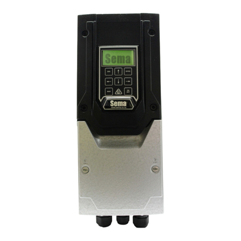
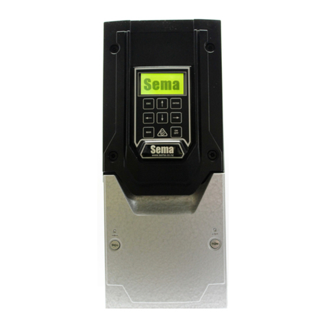
sema VPC3-11 Plus Mk2 User manual

VPC3-11 Plus Mk2 User Manual
For Mk2 Vacuum Pump Controllers 11Kw and above.
V2.12.0

2
This manual applies to the 15 and 22kw Vacuum Pump Controllers
Sema Part Numbers
VPC3-11 11 Kw 400 Vac three phase controller c/w transducer and controller
VPC3-15 15 Kw 400 Vac three phase controller c/w transducer and controller
VPC3-22 22 Kw 400 Vac three phase controller c/w transducer and controller
Contact details
Sema Ltd
P.O. Box 374 Pukekohe 2340 New Zealand
www.sema.co.nz
Tech support and Admin 24/7 +64 9 3580800
Workshop 9 a.m. to 5 p.m. Monday to Friday +64 9 3580700
Fax +64 9 8010031
Contact Maurice Coates on +64 27 9396240
maurice.coates@sema.co.nz

3
Index
Sema Part Numbers & Contact Details 2
Installaon Instrucons 4
Wiring 5-7
Recommended Pracce 7
Plant Check 7
Control Terminals 8
The Keypad 9
Inial Set-Up 10-11
The Running Screen 12
Changing Parameters 12-14
Faults 15
Emergency Mode 15
Supplier Declaraon of Conformity 16
Invertek Drives Manuals and Cercate of Conformity 17
Plant Check?
While on the main running screen press the UP and the DOWN arrow
keys simultaneously to put the unit into PLANT CHECK MODE. This
will cause the controller to ramp slowly up to full speed and stay
there. To cancel this mode either turn the power o or hold the up
and down arrow keys simultaneously again.

4
Installing
Mounng
The 11, 15 and 22Kw drives share the same dimensions:
The controller must be mounted vercally with sucient clearance above and below the drive to allow air to circulate freely.
The operang temperature range is –10 °C to 40°C.
Mount the transducer in the vacuum line as near as is praccal to the claws.
The transducer should be mounted vercally at least 1M from any bends , air
bleeds or regulators.
Try to avoid placing the transducer close to any heat sources, in parcular it
should not be mounted within 1 meter of a steel roof.
Front Rear Side
110mm
171mm
430mm
8.00mm
14.00mm
450mm
252mm

5
Wiring
All wiring must be performed by a suitably qualified person who is familiar with, and ensures compliance
with, the appropriate Electrical Wiring Regulations.
There is no need to use screened mains cabling.
EMC screened cable must be used to connect the controller and motor. An EMC gland must be fitted to
the motor and the preinstalled EMC Gland must be used in the controller.
All wiring that exits the controller including low voltage control cabling must be screened.
The picture above shows the control terminals of the VPC. The terminals are numbered from 1 to 28 and
their funcons are shown on page 8. The wiring and links shown in the picture are installed by Sema and
are necessary for the correct funconing of the controller. Please do not remove or alter any of these.
While there are other oponal components
which may be wired to these terminals (see
page 8) the only addional piece of wiring
which is essenal to make the unit operate is
from the transducer. Connect this as follows:
RED wire to terminal 1.
BLACK (in some cables this may be blue) wire
to terminal 6.
Green/Yellow striped (in some cables this may
have a clear covering) wire to terminal 7 or 9

6
Three Glands are ed to the boom of the VSD.
25mm Gland
for the Main
supply cable
32mm Gland with
a brushed locknut
ed. This is
meant for the
motor cable
20mm Gland for the
Transducer cable and
the controller commu-
nicaon cable
The motor gland has a brushed locknut ed to it (see below). Somemes well intenoned installers remove this gland and
locknut and replace it with an EMC gland. Please note that the brushed locknut has an equal or greater performance to an
EMC gland and that there is nothing to be gained by replacing it. To terminate the screen of the motor cable to the brushed
locknut simply strip back enough of the plasc sheath so that the screen can contact the brush before inserng the cable
through the gland. This will make an extremely eecve EMC earthing connecon and also maintain the units waterproong
rang through the use of an IP68 gland.

7
Power and Motor Connecons
To reverse the direcon of rotaon of the motor change over any two of the three motor
wires (U,V and W)
Ensure that the motor is connected in either Star or Delta as is appropriate to the voltage of the controller.
Typically a single phase 230Vac controller will require the motor to be connected in Delta and a three phase 400Vac controller
will require that the motor is connected in Star. There are excepons to this with some motors supplied from overseas so
please check the motors nameplate.
Connect the main
supply wires to
L1, L2 and L3
Connect the mo-
tor wires to U, V
and W
Connect the
earth wires to
the earth screws
Recommended Pracce
To lessen the risk of the unit being damaged by lightning strikes when it is not in use Sema
recommends that the power be turned o at the compleon of milking.

8
Terminal
Number
Signal Control Terminal Descripon
1+24VDC The RED wire from the transducer is connected here
2Controller The white wire from the controller communicaons cable is connected here
3No user connecon
4No user connecon
5No user connecon
64 to 20 ma analogue The BLACK (In some cables this may be Blue) transducer wire is connected here
70V The CLEAR (In some cables this may be a green and yellow stripe) transducer
wire is connected here. This is the screen.
8No User connecon
90V
10 No User connecon
11 No User connecon
12 No User connecon
13 No User connecon
14 Relay 1 Common
15 Relay 1 N.O. Relay 1 can be programmed to operate a switchable bleed solenoid
16 Relay 1 N.C
17 Relay 2 Common Relay 2 turns on when the unit is running
18 Relay 2 N.O.
19 No User connecon
20 0V
21 +24VDC The commons for the Oponal remote run and remote wash switches should be
connected here.
22 0V
23 No User connecon
24 No User connecon
25 No User connecon
26 No User connecon
27 Remote Run Switch The Remote Run switch should be connected here.
28 Remote Wash Switch The Remote Wash switch should be connected here

9
Seng up and Operaon
Using the keypad
Descripon:
ESC The escape key funcons in the same manner as the escape key on a computer it allows you to exit without sav-
ing parameters and also allows you to go back a step when going through the inial setup roune.
UP ARROW Increases the digit immediately above the cursor when entering parameter values and scrolls
through a menu list.
ENTER Accepts and saves a value which has been entered. Press and hold for 3 seconds to access the Funcon
menu from the main running screen.
MAN Short for Manual. This toggles between Milk and (oponally Herd Test mode and) Wash modes. In wash
mode the vacuum pump runs at full speed. Use this mode for plant checks.
LEFT ARROW Moves the cursor one posion to the le when entering parameter values.
DOWN ARROW Decreases the digit immediately above the cursor when entering parameter values and scrolls
through a menu list.
RIGHT ARROW Moves the cursor one posion to the Right when entering parameter values.
ON OFF Press once to turn the controller o, press again to turn the controller on. The controller will remember
the state of this buon between power ups.
Hint: When entering numbers use the le and right arrow keys to move the cursor and the up and down arrow keys to
change the number above the cursor.

10
Inial Set Up
A few seconds aer powering the unit up for the rst me, or aer re-inialising it, the screen below will be displayed.
The only valid key which can be pressed is the ENTER key and the only way of stopping this screen from appearing is to com-
plete the setup roune.
Please note that, if you make a mistake and enter the wrong value in one of the steps, the ESC key can be used to go back a
step. You can go back as many steps as you like even right to the start of the setup roune if necessary.
The sengs that you enter are only saved aer you complete the last step so, providing you haven’t completed the nal step,
you can always start setup again by turning o the power and then powering up again.
The controller can also be re-inialised. See the ’Changing Parameters’ secon for instrucons on how to do this.
There are 21 steps in the setup roune and they are as follows:-
1. SELECT THE TYPE OF SHED: use the up and down arrows to cycle through the available opons, press the
ENTER key to accept.
2. ENTER THE NUMBER OF SETS OF CLAWS: Use the arrow keys to alter the value. Hint: When enter-
ing numbers use the le and right arrow keys to move the cursor and the up and down arrow keys to change the number
above the cursor.
3. SELECT THE TYPE OF PUMP: use the up and down arrows to cycle through the available opons, press the
ENTER key to accept.
4. SELECT THE TYPE OF TRANSDUCER: The default seng of “Sema Type 1” will almost always be correct
but the unit can also use other types of transducer including the Delaval/John Brooks transducer. Contact Sema for advice if
you are using something other than a Sema type 1 transducer.
5. ENTER THE MOTORS NAMEPLATE VOLTAGE: Use the arrow keys to alter the value.
6. ENTER THE MOTORS NAMEPLATE CURRENT: Use the arrow keys to alter the value.
7. ENTER THE MOTORS NAMEPLATE RPM: Use the arrow keys to alter the value. (Hint: If this is a belt

11
driven pump you can enter the speed of the pump here and then your maximum and minimum speeds will automacally
refer to the pump and not the motor speeds)
8. CONFIGURE RELAY 1: Relay 1 can be congured to operate a switched bleed solenoid. This is a specialised
seng and should not be used if you are unsure of its meaning.
9. RELAY 1 TURN ON RPM: This will only display if you have congured relay 1 to operate a bleed solenoid
10. RELAY 1 TURN OFF RPM: This will only display if you have congured relay 1 to operate a bleed solenoid
11. ENTER THE MOTORS MAXIMUM SPEED: Here you can enter the maximum operang RPM of the
motor. This gure may be adjusted up to 20% more than the motors rated nameplate RPM. If you are in doubt about the maxi-
mum speed that your pump can be operated at then please set this gure to the same value as the Motors Rated Nameplate
speed. Note that this is the value that appears by default.
12. ENTER THE MOTORS MINIMUM SPEED: This gure is also determined by the minimum speed that
your pump can successfully run at. If you are in doubt then the default gure can safely be used.
13. MOTOR DIRECTION CHECK: Pressing the up arrow will cause the motor to run at low speed for a couple of
seconds so that you can check that the direcon of rotaon is correct. If it isn’t then turn o the power and, aer the control-
ler screen goes completely dark, remove the controller terminal cover and swap any two wires connected to U,V and W. Once
this is done turn the power on again and you will be bought back to this step, all of your previous programming will have been
saved. Conrm that the direcon is now correct and then press ENTER to connue.
14. ACCELERATION TIME: This is the me that the motor will take to accelerate from a standsll or when switch-
ing between milk and wash modes. It does not apply when the VPC is controlling the vacuum.
15. DECELERATION TIME: This is the me that the motor will take to decelerate to standsll or when switching
between milk and wash modes. It does not apply when the VPC is controlling the vacuum.
16. VACUUM SETPOINT: This is the vacuum level (in Kpa) that you would like the VPC to control to.
17. WASH VACUUM SETPOINT: By default this is set to 60.0kpa which will run the pump at full speed. If it is
desired to run at another vacuum level this may be entered here.
18.DOES THIS SYSTEM USE AN AIR BLEED: If you answer yes to this then the setup roune will be mod-
ied to guide you through the appropriate sengs when using an oponal air bleed.
19. ADJUST THE REGULATOR: Set the mechanical regulator to the vacuum level requested by the VPC.
20. ADJUST THE AIR BLEED: Wait a few seconds for the vacuum to stabilise and then follow the on screen in-
strucons for seng the air bleed. This step is skipped if you have selected no air bleed in step 17.
21. DOES THIS SYTEM USE A REMOTE ON/OFF SWITCH: If you have ed the oponal remote
switch answer yes, otherwise answer no.
This completes setup, the controller is now fully congured and customised for this shed. Please read the following secons
which describe the running screen and how to alter parameters on a controller which has already been congured.

12
Running
The Running Screen:
Mode
Motor RPM
Motor Current
MODE Five dierent modes may be displayed here:
1. MILK MODE This is the normal mode which is displayed while the unit is running
2. HERD TEST MODE If password protected parameter number 9 (Herd Test Type) is set to anything other than “o”
then pressing the manual key will switch between Milk, Herd Test and Wash modes. Herd test sengs can be adjusted
in funcons 9 and 10.
3. WASH MODE This indicates that the pump will run at full speed
4. LOCAL STOP The on/o buon on the front of the unit has been pressed. Press it again to start the unit.
5. REMOTE STOP The oponal remote run switch is turned o.
Changing Parameters:
To access the parameters (also called funcons) menu press and HOLD the
ENTER key for between 2 and 3 seconds. (A screen will be displayed telling
you to remove your nger aer this me)
SetPoint
Actual Vacuum

13
There are seven parameters which can be altered or accessed without entering a password.
Non Password Protected Parameters:
0.) PASSWORD Enter the password here which unlocks the protected parameters The password is
00004
1.) MINIMUM SPEED The minimum speed of the pump can be adjusted here.
2.) MAXIMUM SPEED The maximum speed of the pump can be adjusted here.
3.) VACUUM SETPOINT Enter the desired vacuum level here
4.) WASH VACUUM SETPOINT Enter the desired vacuum level here
5.) ACCEL TIMEThis is the me that the motor will take to accelerate from a standsll or when switching between
milk and wash modes. It does not apply when the VPC is controlling the vacuum.
6.) DECEL TIME This is the me that the motor will take to decelerate to a standsll or when switching between milk
and wash modes. It does not apply when the VPC is controlling the vacuum.
7.) FAULT HISTORY The fault codes for the last 4 faults that the unit experienced are displayed here. Contact Sema
for an explanaon of the codes.
Password Protected Parameters:
Once the password has been entered correctly in Parameter 0 the password protected funcons become visible. Most of
these funcons require the pump to be stopped before they are adjusted.
Leaving the parameter menu resets the password.
8.) POWER OFF BEHAVIOUR. This parameter determines how the drive responds to a power failure while it is
running. Valid opons are 1.) Ride through, this is the default and the seng most suitable for the majority of installaons.
When set to this the drive will aempt to ride-through the power outage by using energy stored in its capacitors. 2.) Coast to
stop, when set to this the drive will instantly remove power from the motor when the supply power dips. 3.) Fast Decel to
Stop, only use this seng if advised to by Sema Ltd., It is a specialised seng which is not suitable for the majority of installa-
ons.
9.) START DELAY. If it is desired to delay the starng of the vacuum pump a delay me in seconds can be entered
here.
10.) HERD TEST TYPE. Valid opons are : “OFF” herd test mode will be turned o and will not be displayed when
the “MAN” buon is pressed; “KPA ABOVE MILK LEVEL” the herd test vacuum level can be set to be a xed number of KPa
above the milking vacuum level; “FIXED SETPOINT” herd test vacuum level will be set to a dened vacuum level.
11.) HERD TEST LEVEL. Depending on the seng of funcon 9 this seng will either control how many kpa
above milking vacuum the herd test is or be the vacuum seng at which herd test is performed.
12.) PROPORTIONAL GAIN The proporonal gain of the control loop can be adjusted here

14
13.) INTEGRAL TIME The integral me of the control loop can be adjusted here
14.) FAST ACCEL TIME The acceleraon me that the drive uses when it is near the set-point is adjusted here
15.) FAST DECEL TIME The deceleraon me that the drive uses when it is near the set-point is adjusted here
16.) BLEED SOLENOID ON The oponal bleed solenoid turn on RPM can be adjusted here
17.) BLEED SOLENOID OFF The oponal bleed solenoid turn o RPM can be adjusted here
18.) TRANSDUCER OFFSET The transducer can be trimmed so that the vacuum reading agrees with the set-
point.
19.) MOTOR CURRENT Adjust the motor current here if necessary to avoid nuisance tripping.
20.) RE-INITIALISE If the controller is moved to a new shed or a major change is made to the shed that it is installed
in (i.e. a new pump is put in or extra sets of claws are added) then the controller should be re-inialised and the setup roune
re done. Follow the prompts on the screen to achieve this.

15
FAULTS
If a fault occurs that stops the controller running the backlight on the screen will ash rapidly and the fault descripon and
fault number will be displayed. Please write down this number as it will provide Sema Ltd., with important informaon about
the cause of the fault.
If a fault occurs turn o the power, wait unl the controller screen is completely dark and then turn the power back on again. If
the fault is sll present then contact your Dealer or Sema Ltd.
Possible Faults:
Short Circuit. Check the motor cable and the motor for electrical faults
Motor Overloaded. Check that the pump isn’t jammed. Aempt a reset by turning the power o and back on
again. When the motor starts observe its running current (middle gure on the main running screen) and ensure that it is less
than the nameplate current.
Over Voltage. Contact your power company. This will damage the controller it it’s allowed to connue.
Under Voltage. The controller cannot run because there is insucient power. Contact your power company.
Too Hot. The controller is overheated. Check that the cooling ns are not blocked and that the air temperature is not
above 40 degrees Celsius.
Too Cold. The controller must be above –10 degrees Celsius before it will start. If the air temperature is less that this then
gently warm the controller unl it is able to start, once it has started it should generate enough internal heat to keep running.
Transducer Error. The controller is not receiving the correct signal from the vacuum transducer. The most likely
cause of this is a wiring fault. The controller may be run in Emergency Mode to enable milking to be completed.
EMERGENCY MODE
If the controller senses that the transducer is faulty it will not allow the pump to run. This is done for safety reasons to prevent
the possibility of milking taking place with excessively high vacuum levels.
To run the pump when it displays a Transducer fault perform the following acons.
1. Turn o the power and wait unl the controller screen is completely dark.
2. Ensure that no livestock is sll aached to the milking claws.
3. Simultaneously hold down the ON/OFF and MAN keys while turning the power on to the controller.
4. Release these keys and press ENTER when you are prompted to do so. This will run the pump at full speed.
5. BEFORE aempng to milk re-adjust the regulator to give the desired milking vacuum.
The unit can be run in Emergency Mode indenitely without any ill eects providing that the regulator is set correctly. Once
the problem with the transducer is xed the VPC will require you to perform another setup before it will run normally again.

16

17
EMC Compliance
The current range of Sema product is based on the Invertek Drives range of variable speed drives. Units
of 7.5kw and below use the E3 series of drives and units above 7.5kw use the P2 series.
Manuals and compliance information for these drives can be found at www.sema.co.nz or scan the QR
codes below to be taken straight to the relevant document.
For information on how to perform a CE EMC compliant installation please view or download the
appropriate Invertek manual and look in its index for the page labelled “EMC Compliant Installation”.
Invertek E3 Conformity Certificate
Invertek E3 Manual
Invertek P2 Conformity Certificate
Invertek P2 Manual

18

19

20
This manual suits for next models
2
Table of contents
Other sema Controllers manuals
