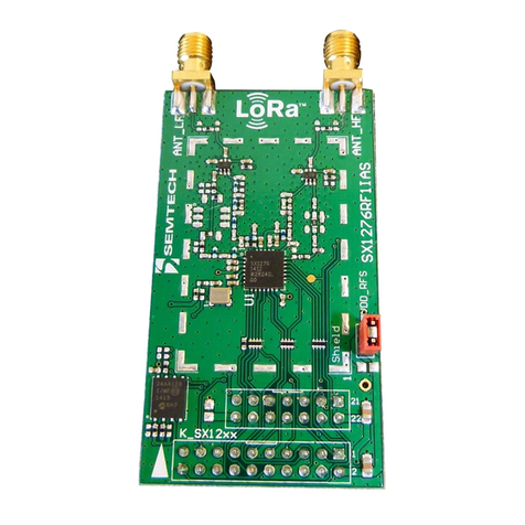
Semtech SX8724SEVK User manual

www.semtech.com
Page 1
ADVANCED COMMUNICATIONS & SENSING USER GUIDE
SX8724SEVK
Evaluation Kit for SX8724S Data Acquisition System
ACS - Revision 1.0 May 2011
© Semtech Corp.
SX8724SEVK USER GUIDE
Evaluation Kit for SX8724S Data Acquisition System
Description
The SX8724SEVK is a platform for SX8724S evaluation
and sensing application prototyping. It consists of a
single board with the ZoomingADC device interfaced to
the computer through a USB gateway.
All SX8724S I/Os are available and placed on breakout
pads for easy access. The tool is intended to be the
interface between the sensor and the PC in order to
ease the handling of the SX8724S.
Equipment Needed
PC with Windows XP or a latest version
Powered USB 2.0 port
Features
Evaluation Board
• Directly connects most types of sensors
• Extended temperature range from -40 to 125°C
• 2.4V to 5.5V operation
• Supply from 5V USB, externally or regulated 3.3V
• USB interface with gateway to the SX8724S
• On board master MCU with flash memory, access
to all IO
•Prototypingarea
• I/Os, board supplies and grounds placed on pads
Graphical User Interface
• Easy settings through registers and controls
• System and device performance analysis tool
• Save and load configurations
•Logtofile
SX8724S ZoomingADC System Evaluation
• Up to 16-bit differential data acquisition
• Programmable gain: (1/12 to 1000)
• Sensor offset compensation up to 15 times full
scale of input signal
• 3 differential or 6 single-ended signal inputs
• Programmable Resolution versus Speed versus
Supply current
• External reference input voltage
• Internal reference output
• Digital outputs to bias sensors
• Low-power (250 uA for 16b @ 500 S/s)
Digital Interface
• Access to SPI signal
•ADCconversionready
•2GPIO
• Possibility to chain boards on the same bus
Application Examples in this User Guide
• Interfacing your first pressure sensor
Ordering Informations
EVK Part Number Function
SX8724SEVK SX8724S (SPI) Evaluation

ACS - Revision 1.0 May 2011
© Semtech Corp. www.semtech.com
Page 2
Section Page
TABLE OF CONTENT
ADVANCED COMMUNICATIONS & SENSING USER GUIDE
SX8724SEVK
Evaluation Kit for SX8724S Data Acquisition System
GETTING STARTED . . . . . . . . . . . . . . . . . . . . . . . . . . . . . . . . . . . . . . . . . . . . . . . . . . . . . . . . . . . . . . 4
1 Introduction. . . . . . . . . . . . . . . . . . . . . . . . . . . . . . . . . . . . . . . . . . . . . . . . . . . . . . . . . . . . . . . . . . . . . . . . . . . 4
2 Evaluation Kit Contents . . . . . . . . . . . . . . . . . . . . . . . . . . . . . . . . . . . . . . . . . . . . . . . . . . . . . . . . . . . . . . . . . 4
3 Board Overview . . . . . . . . . . . . . . . . . . . . . . . . . . . . . . . . . . . . . . . . . . . . . . . . . . . . . . . . . . . . . . . . . . . . . . . 5
4 Software Installation. . . . . . . . . . . . . . . . . . . . . . . . . . . . . . . . . . . . . . . . . . . . . . . . . . . . . . . . . . . . . . . . . . . . 6
4.1 About Microsoft .NET Framework. . . . . . . . . . . . . . . . . . . . . . . . . . . . . . . . . . . . . . . . . . . . . . . . . . . . . . . . 7
5 Board Connection and Drivers Installation (first time) . . . . . . . . . . . . . . . . . . . . . . . . . . . . . . . . . . . . . . . . . . 8
HARDWARE DESCRIPTION . . . . . . . . . . . . . . . . . . . . . . . . . . . . . . . . . . . . . . . . . . . . . . . . . . . . . . . . . 9
6 Board Schematic . . . . . . . . . . . . . . . . . . . . . . . . . . . . . . . . . . . . . . . . . . . . . . . . . . . . . . . . . . . . . . . . . . . . . . 9
7 User Interfaces. . . . . . . . . . . . . . . . . . . . . . . . . . . . . . . . . . . . . . . . . . . . . . . . . . . . . . . . . . . . . . . . . . . . . . . 10
7.1 Prototyping Area . . . . . . . . . . . . . . . . . . . . . . . . . . . . . . . . . . . . . . . . . . . . . . . . . . . . . . . . . . . . . . . . . . . . 11
8 Power Supply. . . . . . . . . . . . . . . . . . . . . . . . . . . . . . . . . . . . . . . . . . . . . . . . . . . . . . . . . . . . . . . . . . . . . . . . 12
8.1 Power Sources Specifications. . . . . . . . . . . . . . . . . . . . . . . . . . . . . . . . . . . . . . . . . . . . . . . . . . . . . . . . . . 12
8.2 Power Supply Selection . . . . . . . . . . . . . . . . . . . . . . . . . . . . . . . . . . . . . . . . . . . . . . . . . . . . . . . . . . . . . . 13
9 USB Interface. . . . . . . . . . . . . . . . . . . . . . . . . . . . . . . . . . . . . . . . . . . . . . . . . . . . . . . . . . . . . . . . . . . . . . . . 14
9.1 Gateway to SX8724S . . . . . . . . . . . . . . . . . . . . . . . . . . . . . . . . . . . . . . . . . . . . . . . . . . . . . . . . . . . . . . . . 14
10 EVK Bill of Materials List . . . . . . . . . . . . . . . . . . . . . . . . . . . . . . . . . . . . . . . . . . . . . . . . . . . . . . . . . . . . . . . 16
11 Board Physical Dimensions . . . . . . . . . . . . . . . . . . . . . . . . . . . . . . . . . . . . . . . . . . . . . . . . . . . . . . . . . . . . . 18
GRAPHICAL USER INTERFACE . . . . . . . . . . . . . . . . . . . . . . . . . . . . . . . . . . . . . . . . . . . . . . . . . . . . . 19
12 Software Tool Overview. . . . . . . . . . . . . . . . . . . . . . . . . . . . . . . . . . . . . . . . . . . . . . . . . . . . . . . . . . . . . . . . 19
13 Main Window . . . . . . . . . . . . . . . . . . . . . . . . . . . . . . . . . . . . . . . . . . . . . . . . . . . . . . . . . . . . . . . . . . . . . . . . 20
13.1 Menu Tool Bar. . . . . . . . . . . . . . . . . . . . . . . . . . . . . . . . . . . . . . . . . . . . . . . . . . . . . . . . . . . . . . . . . . . . . . 20
13.2 Window Tool Bar. . . . . . . . . . . . . . . . . . . . . . . . . . . . . . . . . . . . . . . . . . . . . . . . . . . . . . . . . . . . . . . . . . . . 22
13.3 Status Bar . . . . . . . . . . . . . . . . . . . . . . . . . . . . . . . . . . . . . . . . . . . . . . . . . . . . . . . . . . . . . . . . . . . . . . . . . 23
13.4 ZoomingADC controls. . . . . . . . . . . . . . . . . . . . . . . . . . . . . . . . . . . . . . . . . . . . . . . . . . . . . . . . . . . . . . . . 24
13.5 Voltage Control . . . . . . . . . . . . . . . . . . . . . . . . . . . . . . . . . . . . . . . . . . . . . . . . . . . . . . . . . . . . . . . . . . . . . 27
13.6 Estimated Device Performances. . . . . . . . . . . . . . . . . . . . . . . . . . . . . . . . . . . . . . . . . . . . . . . . . . . . . . . . 27
13.7 Display Chart. . . . . . . . . . . . . . . . . . . . . . . . . . . . . . . . . . . . . . . . . . . . . . . . . . . . . . . . . . . . . . . . . . . . . . . 29
13.8 Log Data to File. . . . . . . . . . . . . . . . . . . . . . . . . . . . . . . . . . . . . . . . . . . . . . . . . . . . . . . . . . . . . . . . . . . . . 30
14 ZoomingADC Data Display Window. . . . . . . . . . . . . . . . . . . . . . . . . . . . . . . . . . . . . . . . . . . . . . . . . . . . . . . 31
14.1 ZoomingADC data display panel. . . . . . . . . . . . . . . . . . . . . . . . . . . . . . . . . . . . . . . . . . . . . . . . . . . . . . . . 31
14.2 Histogram Panel - Noise Analysis. . . . . . . . . . . . . . . . . . . . . . . . . . . . . . . . . . . . . . . . . . . . . . . . . . . . . . . 32
14.3 Measured System Performances . . . . . . . . . . . . . . . . . . . . . . . . . . . . . . . . . . . . . . . . . . . . . . . . . . . . . . . 32
15 Registers Display Window . . . . . . . . . . . . . . . . . . . . . . . . . . . . . . . . . . . . . . . . . . . . . . . . . . . . . . . . . . . . . . 34
16 Verification Mode Window . . . . . . . . . . . . . . . . . . . . . . . . . . . . . . . . . . . . . . . . . . . . . . . . . . . . . . . . . . . . . . 34
APPLICATION EXAMPLES . . . . . . . . . . . . . . . . . . . . . . . . . . . . . . . . . . . . . . . . . . . . . . . . . . . . . . . . . 35
17 Interfacing your first pressure sensor. . . . . . . . . . . . . . . . . . . . . . . . . . . . . . . . . . . . . . . . . . . . . . . . . . . . . . 35
17.1 Introduction . . . . . . . . . . . . . . . . . . . . . . . . . . . . . . . . . . . . . . . . . . . . . . . . . . . . . . . . . . . . . . . . . . . . . . . . 35
17.2 Pressure Sensor . . . . . . . . . . . . . . . . . . . . . . . . . . . . . . . . . . . . . . . . . . . . . . . . . . . . . . . . . . . . . . . . . . . . 35
17.3 Using the Evaluation Board and the GUI . . . . . . . . . . . . . . . . . . . . . . . . . . . . . . . . . . . . . . . . . . . . . . . . . 39
17.4 Reading the sensor using the GUI . . . . . . . . . . . . . . . . . . . . . . . . . . . . . . . . . . . . . . . . . . . . . . . . . . . . . . 40

ACS - Revision 1.0 May 2011
© Semtech Corp. www.semtech.com
Page 3
Section Page
TABLE OF CONTENT
ADVANCED COMMUNICATIONS & SENSING USER GUIDE
SX8724SEVK
Evaluation Kit for SX8724S Data Acquisition System
17.5 Reference Voltage Selection. . . . . . . . . . . . . . . . . . . . . . . . . . . . . . . . . . . . . . . . . . . . . . . . . . . . . . . . . . . 40
17.6 ZoomingADC™ Configuration. . . . . . . . . . . . . . . . . . . . . . . . . . . . . . . . . . . . . . . . . . . . . . . . . . . . . . . . . . 42
17.7 ADC Configuration . . . . . . . . . . . . . . . . . . . . . . . . . . . . . . . . . . . . . . . . . . . . . . . . . . . . . . . . . . . . . . . . . . 45
17.8 Noise Cancellation . . . . . . . . . . . . . . . . . . . . . . . . . . . . . . . . . . . . . . . . . . . . . . . . . . . . . . . . . . . . . . . . . . 47
17.9 LSB Equivalence. . . . . . . . . . . . . . . . . . . . . . . . . . . . . . . . . . . . . . . . . . . . . . . . . . . . . . . . . . . . . . . . . . . . 48
17.10 ZoomingADC™ Benefits. . . . . . . . . . . . . . . . . . . . . . . . . . . . . . . . . . . . . . . . . . . . . . . . . . . . . . . . . . . . . . 49

www.semtech.com
Page 4
ADVANCED COMMUNICATIONS & SENSING USER GUIDE
SX8724SEVK
Evaluation Kit for SX8724S Data Acquisition System
ACS - Revision 1.0 May 2011
© Semtech Corp.
GETTING STARTED
1Introduction
This section describes a typical configuration for operating the evaluation board of the SX8724S with
ZoomingADC.
The SX8724S is a signal conditioner based on Semtech's ultra low power ZoomingADC™ technology. It
directly connects most types of miniature sensors with a general purpose microcontroller.
The SX8724SEVK is a USB based evaluation tool designed to allow simple and easy evaluation of the
suitability of the SX8724S device for a given application.
The analog input signal can be entered either in differential or single ended. Refer to the datasheet for the
impact of driving an analog input in single or in differential.
2EvaluationKitContents
The SX8724SEVK evaluation kit consists of:
a “Read me first” sheet
an Evaluation Board
one USB cable
a CDROM containing:
• Software Installer including MS .NET framework 3.5 and USB drivers
• SX8724SEVK User Guide (this document)

www.semtech.com
Page 5
ADVANCED COMMUNICATIONS & SENSING USER GUIDE
SX8724SEVK
Evaluation Kit for SX8724S Data Acquisition System
ACS - Revision 1.0 May 2011
© Semtech Corp.
3 Board Overview
The picture below describes the main zones and functions accessible on the SX8724SEVK.
Figure 1. SX8724SEVK Board Overview
USB Gateway Interface
Isolate/connect device
Analog Interface
Prototyping Area
Acquisition Device
& Power Management
& Digital Interface

www.semtech.com
Page 6
ADVANCED COMMUNICATIONS & SENSING USER GUIDE
SX8724SEVK
Evaluation Kit for SX8724S Data Acquisition System
ACS - Revision 1.0 May 2011
© Semtech Corp.
4 Software Installation
If the evaluation kit is supplied with an insert sheet, follow the instruction on the insert sheet. The latest
software revision can be downloaded on Semtech website.
1. Put the CDROM in your computer and browse the contents of the CD, open the
SX8724xEvaluationKitSetup.exe file manually. It can be found in the root of the CD-ROM. Click on Next> to
start the installation
Figure 2. Installation Screen

www.semtech.com
Page 7
ADVANCED COMMUNICATIONS & SENSING USER GUIDE
SX8724SEVK
Evaluation Kit for SX8724S Data Acquisition System
ACS - Revision 1.0 May 2011
© Semtech Corp.
2. Choose the installation directory. The software must be installed on a local directory. Click on Next> to
confirm the path.
3. Follow the on-screen installation guidelines until the process is completed. Please note that .NET
Framework 3.5 and the PIC USB driver will be automatically installed if not detected on your computer.
(Administrator rights may be needed).
4. The GUI software and .Net Framework are now installed on your computer.
4.1 About Microsoft .NET Framework
The Microsoft .NET Framework 3.5 is required to run the software. The software installer will install the it
automatically if not present on your computer.
Details and installation information about the .NET Framework are available on Microsoft web site (http://
www.microsoft.com). Then go to the Download section.
There are multiple versions of the .NET Framework available from Microsoft, and they can be installed side-by-
side on the same computer. Contact your system administrator for more details.
Figure 3. Software Install Location

www.semtech.com
Page 8
ADVANCED COMMUNICATIONS & SENSING USER GUIDE
SX8724SEVK
Evaluation Kit for SX8724S Data Acquisition System
ACS - Revision 1.0 May 2011
© Semtech Corp.
5 Board Connection and Drivers Installation (first time)
1. Connect the board to the PC with the USB interface. The board is powered via the USB and will be
detected as new USB peripheral. Choose the “Install the software automatically (Recommended)” option
and click on the Next> button.
2. Windows will search for the associated driver and install the board as new peripheral.
3. Follow the on-screen installation guidelines until the process is completed. Driver compatibility screens
may appear during the installation procedure. Validate always by clicking the “Continue Anyway button”:
4. The drivers are now installed. The board and its dedicated software are ready to be used. Launch
SX8724xEVK software from the Windows Start menu.

www.semtech.com
Page 9
ADVANCED COMMUNICATIONS & SENSING USER GUIDE
SX8724SEVK
Evaluation Kit for SX8724S Data Acquisition System
ACS - Revision 1.0 May 2011
© Semtech Corp.
HARDWARE DESCRIPTION
6BoardSchematic
MOSI
SCLK
GND
SS
READY
VBOARD
VUSB
1
2
J8
GND
1
2
3
4
5
6
J1 AGND
0.1uF
C13
RB6
RB4
RC7
Ferrite
F2
VBUS 1
D- 2
D+ 3
GND 5
SHL D 4
J6
H2959CT-ND
Ferrite
F1
10uF
C3
NC
C6 1uF
C7
100nF
C8
1uF
C4
100nF
C5
D1
Re d
470R
R3
SHDN
3
NC
4
VSS
2
VOUT 5
VIN
1
U3 MCP1802
4.7pF
C1
4.7pF
C2
VLDO
OSC2
OSC1
W2
W3
RC5
RC4
RC3
RC2
RC1
RC0
RB5
RB7
W1
AGND
VBUS
VBOARD
PGD/D+
PGC/D-
PGD/D+
PGC/D-
VBATT
MCLR/VP P
1
2
3
4
J2 VPUMP
MISO/READY
RC6
VDD 1
RA5/I OCA5/OSC1/CLKIN
2RA4/AN3/I OCA3/OSC2/CLK OUT
3RA3/I OCA3/MCLR/VPP
4
RC5/CCP 1/P1A/T0CK I 5
RC4/P 1B/C12OUT/SRQ 6
RC3/AN7/P 1C/C12I N3-/PGM 7
RC6/AN8/SS/T13CK I /T1OSCI 8
RC7/AN9/SDO/T1OSCO 9
RB7/I OCB7/TX/CK
10 RB6/I OCB6/SCK /SCL
11 RB5/AN11/I OCB5/RX/DT
12 RB4/AN10/I OCB4/SDI /SDA
13
RC2/AN6/P 1D/C12I N2-/CVref/I NT2 14
RC1/AN5/C12I N1-/INT1/Vref- 15
RC0/AN4/C12I N+/INT0/Vref+ 16
VUSB 17
RA1/I OCA1/D- /PGC
18 RA0/I OCA0/D+/PGD
19
VSS
20
U2
PIC18F14K50-E/SS
Analog
POWER
l
SS
VEXT
USB
INTERFACES
Acquisition
GATEWAY
21
HC49
Y1
22pF
C9
22pF
C10
GND
12 MHz
1
2
3
4
5
6
J7
PI CK IT Serial
10KR1
GND
0RR2
VPP
VDD
GND
DAT
PCLK
T1G PGC/D-
VBOARD
PGD/D+
MCLR/VPP
VEXT
22nF
C14
PROG
GNDGND
GND
GND
GNDGND
GNDGNDGND
GND
GND
W28
W26
W29
W27
W25
MISO/READY
MOSI
SS
SCLK
10KR5
VBATT
BOARD VOLTAGE SELECTOR
W17
W18
W19
W20
GND
VBOARDVUSB
0.47uF
C11
0.1uF
C12
GND
RB6
RB4
RB5
RC2
RC1
RC0
W5
W6
W7
W8
W9
W10
W11
W12
W13
W14
W15
W16
VBOARD
RC5
RC4
RC3
RC6
RC7
RB7
W4
INTERFACES
MCLR/VPP
OSC2
OSC1
V_supply
MISO/READY
AC2
AC3
AC4
AC5
AC6
AC7
D0
D1
AC3
1
AC4
4
AC5
5
AC6
2
AC7
3
VBATT 6
VSS 7
READY 8
D1
9
SS 10
MISO/READY 11
D0
12
MOSI 13
SCK L 14
VPUMP 15
AC2
16
VSS 17
U1
S X8 724S
set_protocol
R7
AGND
VBOARD
RA5
RA4
RA3
RC5
RC4
RC3
RC6
RC7
RB7
RB6
RB5
RB4
RC2
RC1
BOOT LOADER
Wboot
1K
R4
GND
10K
W32READY

www.semtech.com
Page 10
ADVANCED COMMUNICATIONS & SENSING USER GUIDE
SX8724SEVK
Evaluation Kit for SX8724S Data Acquisition System
ACS - Revision 1.0 May 2011
© Semtech Corp.
7 User Interfaces
The analog interface gives access to the ZoomingADC inputs. The digital interface gives access to the GPIO
pins, the PC gateway connections and the power supplies. The analog and digital connections are available
on single row 2.54mm connectors and on the bare PCB next to the prototyping area.
The connections points are available for industrial PCB terminal blocks and on the bare PCB next to the
SX8724S
Figure 4. Analog Interface Schematic
Figure 5. SX8724S Interface on the Board
MOSI
SCLK
SS
READY
1
2
3
4
5
6
J1 AGND
0.1uF
C13
AGND
VBATT
1
2
3
4
J2 VPUMP
MISO/READY
Analog
Digital
SS
Acquisition
22nF
C14
INTERFACES
MISO/READY
AC2
AC3
AC4
AC5
AC6
AC7
D0
D1
AC3
1
AC4
4
AC5
5
AC6
2
AC7
3
VBATT 6
VSS 7
READY 8
D1
9
SS 10
MISO/READY 11
D0
12
MOSI 13
SCK L 14
VPUMP 15
AC2
16
VSS 17
U1
SX8724S
4
Analog interface Digital interface
+ Vref,in and Vref,out
Connect SX8724S
VBATT pin to supply
(or measure current)
Connect SX8724S READY
signal to gateway
Connect SPI interface to SX8724S
(pull-ups are on gateway side)

www.semtech.com
Page 11
ADVANCED COMMUNICATIONS & SENSING USER GUIDE
SX8724SEVK
Evaluation Kit for SX8724S Data Acquisition System
ACS - Revision 1.0 May 2011
© Semtech Corp.
7.1 Prototyping Area
Using the prototyping area, one can set its own application only using the SX8724S and bypassing the
onboard gateway.
Figure 6. Prototyping Area

www.semtech.com
Page 12
ADVANCED COMMUNICATIONS & SENSING USER GUIDE
SX8724SEVK
Evaluation Kit for SX8724S Data Acquisition System
ACS - Revision 1.0 May 2011
© Semtech Corp.
8PowerSupply
The board provides different power supply voltage possibilities; the following paragraphs describe how to
configure and use them.
8.1 Power Sources Specifications
The board can be powered through three different sources:
1. VBUS: USB power coming from the PC.
2. VLDO: 3.3V Regulated voltage.
3. VEXT: External source applied on VEXT interface.
Input analog voltages specified in the device datasheet.
Table 1. Power Sources Specifications
Voltage range Min Typ Max Unit Comment
VBUS 4.5 5 5.5 V DC, Unregulated
VLDO1
1. Temperature range from -40 to 85°C
3.3 V DC, Regulated
VEXT 2.4 - 5.5 V DC, Unregulated 2
2. External power supply
Board current driving capability
-100mA

www.semtech.com
Page 13
ADVANCED COMMUNICATIONS & SENSING USER GUIDE
SX8724SEVK
Evaluation Kit for SX8724S Data Acquisition System
ACS - Revision 1.0 May 2011
© Semtech Corp.
8.2 Power Supply Selection
Available supply voltages vs. selected power source is described below.
IMPORTANT NOTICE
- DO NEVER CONNECT VEXT JUMPER IF EXTERNAL VOLTAGE IS HIGHER THAN 5.5VDC.
- CONNECT ONLY ONE JUMPER ON THIS SELECTOR
The picture below shows the selector. User should place the jumper on the desired SX8724S supply voltage
value.
Figure 7. Power Supply Schematic
Figure 8. SX8724SEVK Power Supply Selector
1
2
J8
GND
Ferrite
F2
VBUS 1
D- 2
D+ 3
GND 5
SHL D 4
J6
H2959CT-ND
Ferrite
F1
10uF
C3
NC
C6 1uF
C7
100nF
C8
1uF
C4
100nF
C5
ON
Re d
470R
R3
SHDN
3
NC
4
VSS
2
VOUT 5
VI N
1
U3 MCP1802
27pF
C1
27pF
C2
VLDO W3
W1
W2VBUS
VBOARD
PGD/D+
PGC/D-
VEXT
USB
INTERFACES
VEXT
GNDGND
GND
GND
GNDGND
GNDGNDGND
GND
GND
BOARD VOLTAGE SELECTOR
W4
Power jumper
Power LED
Enter here with an
external power supply
External voltage
5V from USB
Regulated 3.3V
Board voltage
Board Voltage Selectors

www.semtech.com
Page 14
ADVANCED COMMUNICATIONS & SENSING USER GUIDE
SX8724SEVK
Evaluation Kit for SX8724S Data Acquisition System
ACS - Revision 1.0 May 2011
© Semtech Corp.
9USBInterface
9.1 Gateway to SX8724S
The USB gateway is a complete interface to drive the SX8724S on the board. The knowledge, implementation
or modification of this gateway is not required for evaluation.
This interface is used to communicate with the GUI, but can also enable automation with external processes
such as Python, MATLAB, and LabVIEW.
Figure 9. PIC Gateway Schematic
Figure 10. PIC Gateway on the Board
GND
VBOARD
VUSB
RB6
RB4
RC7
OSC2
OSC1
RC5
RC4
RC3
RC2
RC1
RC0
RB5
RB7
PGD/D+
PGC/D-
MCLR/VPP
RC6
VDD 1
RA5/I OCA5/OSC1/CL K IN
2RA4/AN3/I OCA3/OSC2/CL K OUT
3RA3/I OCA3/MCL R/VP P
4
RC5/CCP 1/P1A/T0CK I 5
RC4/P 1B/C12OUT/SRQ 6
RC3/AN7/P 1C/C12I N3-/PGM 7
RC6/AN8/SS/T13CK I/T1OSCI 8
RC7/AN9/SDO/T1OSCO 9
RB7/I OCB7/TX/CK
10 RB6/I OCB6/SCK /SCL
11 RB5/AN11/I OCB5/RX/DT
12 RB4/AN10/I OCB4/SDI /SDA
13
RC2/AN6/P 1D/C12I N2- /CVref/I NT2 14
RC1/AN5/C12I N1-/INT1/Vref- 15
RC0/AN4/C12I N+/INT0/Vref+ 16
VUSB 17
RA1/I OCA1/D- /PGC
18 RA0/I OCA0/D+/P GD
19
VSS
20
U2
PIC18F14K50-E/SS
2 1
HC49
Y1
22pF
C9
22pF
C10
GND
12 MHz
GND
VUSB
0.47uF
C11
0.1uF
C12
GND
BOOT LOADER J9
1K
R4
GND
VBOARD
PICKit programmer/debugger interface
Bootloader mode control
PIC gateway
Pin access to the PIC gateway
USB interface

www.semtech.com
Page 15
ADVANCED COMMUNICATIONS & SENSING USER GUIDE
SX8724SEVK
Evaluation Kit for SX8724S Data Acquisition System
ACS - Revision 1.0 May 2011
© Semtech Corp.
9.1.1 Bootloader Mode
The BOOT LOADER (J9) jumper allows the user to set the onboard PIC18F14K50 in bootloader mode and to
program it. One can then update the gateway with the latest driver from Semtech website or set its own
solution1using the SPI interface (see 7.1. Prototyping Area).
By default, the jumper is not connected.
To enter in bootloader mode, shortcut the BOOT LOADER (J9) jumper and restart the PIC by unplug-plug the
SUPPLY jumper or disconnect-connect the USB cable (see Figure 10 on page 14).
9.1.2 PICkit Programming Interface
This interface is used to program the board with a Microchip PICkit 3 Programmer/Debugger.
1. Semtech does not provide support for modified Gateway software other than the official releases available on the website.
Figure 11. PICKIT Programmer Interface
1
2
3
4
5
6
J7
PI CK IT Serial
10KR1
GND
0RR2
VPP
VDD
GND
ICSPDAT
ICSPCLK
T1G PGC/D-
VBOARD
PGD/D+
MCL R/VP P
PROG

www.semtech.com
Page 16
ADVANCED COMMUNICATIONS & SENSING USER GUIDE
SX8724SEVK
Evaluation Kit for SX8724S Data Acquisition System
ACS - Revision 1.0 May 2011
© Semtech Corp.
10 EVK Bill of Materials List
Table 2. SX8724SEVK Bill of Material
Ref Val Package Description Manufacturer Part#
IC
U1 MLPQ-16 4x4 SX8724S acquisition system SEMTECH SX8724SWLTDT
U2 SSOP-20, 6.5mm pitch PIC Gateway Microchip PIC18F14K50-E/SS
U3 SOT23-5 3.3V REG LDO 300MA Microchip MCP1802T-3302I/OT
Connectors
J6 Surface Mount, Right Angle,
Horizontal Connector mini USB2.0 Interconnects UX60-MB-5ST
J7 Through Hole, Right Angle Header BRKWAY .100 6POS
R/A Tyco Electronics 9-103325-0-06
Crystal
Y1 Surface Mount, HC49/US Crystal 12.00000 MHZ
18pF SMD Abracon Corporation ABLS-12.000MHZ-K4T
Jumpers/selectors
W1,
W2,
W3, Through Hole, 2.54mm 3x2 header
+ 1x RED jumper
W4,
W25,
W32 Through Hole, 2.54mm 3x 1x2 headers
+ 3x BLACK jumper
W26,
W27,
W28,
W29
Through Hole, 2.54mm 4x2 header
+ 4x BLACK jumper
Ferrites Bead
F1, F2 SMD 0805 Ferrite 1.5A 40 Ohm Steward PZ2012D400-3R0TF
Resistors
R1,
R6,
R8,
R9
10K SMD 0603
R2 0R SMD 0603 PICKIT prog
R3 470R SMD 0603 LED current limiting resistor
R4 1K SMD 0603 Protection for Bootloader
bypass
Capacitors
C1,
C2, 47pF SMD 0603
C3 10uF SMD 0805

www.semtech.com
Page 17
ADVANCED COMMUNICATIONS & SENSING USER GUIDE
SX8724SEVK
Evaluation Kit for SX8724S Data Acquisition System
ACS - Revision 1.0 May 2011
© Semtech Corp.
C4,
C7 1uF SMD 0603
C5,
C8,
C12,
C13
100nF SMD 0603
C9,
C10 22pF SMD 0603
C11 47nF SMD 0603
C14 22nF SMD 0603
Table 2. SX8724SEVK Bill of Material
Ref Val Package Description Manufacturer Part#

www.semtech.com
Page 18
ADVANCED COMMUNICATIONS & SENSING USER GUIDE
SX8724SEVK
Evaluation Kit for SX8724S Data Acquisition System
ACS - Revision 1.0 May 2011
© Semtech Corp.
11 Board Physical Dimensions
Figure 12. SX8724SEVK Board Overview
4

www.semtech.com
Page 19
ADVANCED COMMUNICATIONS & SENSING USER GUIDE
SX8724SEVK
Evaluation Kit for SX8724S Data Acquisition System
ACS - Revision 1.0 May 2011
© Semtech Corp.
GRAPHICAL USER INTERFACE
12 Software Tool Overview
The SX8724SEVK includes a graphical user interface (GUI) that provides simplified access to all key registers
on the board. It uses intuitive controls and popup menus to write settings from the hardware.
This GUI takes high level input from the user and computes the required low level register values. With the
GUI, the user is not required to compute complicated equations to determine which values must be written
for board operation. In addition, the GUI simplifies analog interfacing by providing controls that simplify
alignment of analog functions.
The figure below illustrates the SX8724xEVK graphical user interface (GUI). Each of the numbered captions
corresponds to a proceeding chapter within the sections which correspond to the description of that GUI
feature:
1. see section 13.1. Menu Tool Bar in page 20
2. see section 13.2. Window Tool Bar in page 22
3. see section 13.3. Status Bar in page 23
4. see section 13.4. ZoomingADC controls in page 24
5. see section 13.4.5. General Controls in page 25
6. see section 13.5. Voltage Control in page 27
7. see section 13.6. Estimated Device Performances in page 27
8. see section 13.7. Display Chart in page 29
Figure 13. GUI Main Window
4.
5.
7.
6.
8.
1. 2.
3.

www.semtech.com
Page 20
ADVANCED COMMUNICATIONS & SENSING USER GUIDE
SX8724SEVK
Evaluation Kit for SX8724S Data Acquisition System
ACS - Revision 1.0 May 2011
© Semtech Corp.
13 Main Window
13.1 Menu Tool Bar
The Menu tool bar contains four drop down menus, File Menu, Action Menu, Tools Menu and Help Menu.
13.1.1 File Menu
Connect / Disconnect allows the connection or disconnection of the board from the host PC. This
functionality can also be accessed through the short cut buttons of the Window Toolbar (see 13.2.
Window Tool Bar).
Open Config… allows for the opening of SX8724xEVK configuration files (.cfg). This is implemented
through a standard Windows file dialog box and may also be accessed through the short cut buttons of
the Window Toolbar.
Save Config allows for SX8724xEVK configuration files (.cfg) to be saved. This is implemented through a
standard Windows file dialog box. The default file name is the last saved configuration file.
Save Config as… prompts for a new file name before saving, allowing for multiple configuration files to be
saved and may also be accessed through the short cut buttons of the Window Toolbar.
Exit closes the application.
13.1.2 Action Menu
Reset resets the SX8724S configuration registers to the default values by writing the SX8724S reset
register.
Refresh reads all SX8724S registers and updates the GUI controls.
Show registers toggles the SX8724S Registers display window and may also be accessed through the short
cut buttons of the Window Toolbar. The register display window indicates the status of SX8724S
Figure 14. File Menu Options
Table of contents
Other Semtech Microcontroller manuals
Popular Microcontroller manuals by other brands

Texas Instruments
Texas Instruments AFE722 Series user guide

Segger
Segger J-Link user guide

adafruit learning system
adafruit learning system ItsyBitsy 32u4 manual

ARM
ARM KEIL Infineon XMC4500 Relax Lite Board quick start guide

ST
ST FP-SNS-SMARTAG1 quick start guide

mikroElektronika
mikroElektronika CLICKER 2 FOR FT90X manual

Philips
Philips P89LPC938 user manual

Spectrum Digital
Spectrum Digital TMS320C6416T DSK Technical reference

Terasic
Terasic C5P user manual

NXP Semiconductors
NXP Semiconductors Freescale TWR-MECH quick start guide

Xilinx
Xilinx MIcroBlaze Development Spartan-3E 1600E Kit Getting started

Intrinsyc
Intrinsyc LANTRONIX Open-Q 820 user guide