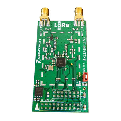
Semtech SX1233SKA User manual

Revision 1.0 STD – February 2010 Page 1 of 31 www.semtech.com
© Semtech 2011
SX1233SKA
USER GUIDE
SX1233SKA
USER GUIDE

Revision 1.0 STD – February 2010 Page 2 of 31 www.semtech.com
© Semtech 2011
SX1233SKA
USER GUIDE
Table of Contents
Table of Contents..........................................................................................................................................2
Index of Figures ............................................................................................................................................3
Index of Tables..............................................................................................................................................3
1Introduction............................................................................................................................................5
2Getting Started.......................................................................................................................................7
2.1 Evaluation Kit Contents ...............................................................................................................7
2.2 Installation....................................................................................................................................8
2.3 SX1233SKA Overview.................................................................................................................8
3SX1233 Quick Start Guide.....................................................................................................................8
4SX1233SKA Software Description.........................................................................................................8
4.1 Overview......................................................................................................................................8
4.2 Menu Tool Bar.............................................................................................................................9
4.2.1 File Menu.................................................................................................................................9
4.2.2 Action Menu...........................................................................................................................10
4.2.3 Tools Menu............................................................................................................................10
4.2.4 Help Menu.............................................................................................................................11
4.3 Window Toolbar.........................................................................................................................11
4.4 Status Bar..................................................................................................................................13
4.5 Operating Modes Control Box...................................................................................................13
4.6 Irq Status Indicator.....................................................................................................................13
4.7 Antenna Switch Control Box......................................................................................................14
5Configuration Registers Tabs..............................................................................................................15
5.1 Common Configuration Registers Tab......................................................................................15
5.1.1 Modulation Mode Window.....................................................................................................16
5.2 Transmitter Configuration Register Tab ....................................................................................16
5.3 Receiver Configuration Register Tab ........................................................................................17
5.3.1 Rx Bandwidth ........................................................................................................................18
5.3.2 LNA Gain Window.................................................................................................................18
5.3.3 AFC / FEI...............................................................................................................................19
5.3.4 RSSI......................................................................................................................................19
5.3.5 Continuous-Time Digital AGC...............................................................................................20
5.4 Irq & Mapping Configuration Register Tab................................................................................20
5.5 Packet Handler Configuration Register Tab..............................................................................22
5.5.1 Sync Word.............................................................................................................................23
5.5.2 AutoMode Operation.............................................................................................................23
5.5.3 Packet Log.............................................................................................................................23
5.5.4 Packet Handler GUI Limitations............................................................................................24
5.6 Temperature Configuration Register Tab..................................................................................24
6Registers Display Window...................................................................................................................26
7Advanced Operating Modes ................................................................................................................27
7.1 Packet Communications Test....................................................................................................27
7.1.1 Transmitter Mode Configuration............................................................................................27
7.1.2 Receiver Mode Configuration................................................................................................27
7.2 Test Mode Window....................................................................................................................27
7.3 Verification Mode.......................................................................................................................28
7.4 RSSI Analyzer ...........................................................................................................................28
7.5 Spectrum Analyzer ....................................................................................................................29
8Compatibility with Earlier Silicon Revisions.........................................................................................30

Revision 1.0 STD – February 2010 Page 3 of 31 www.semtech.com
© Semtech 2011
SX1233SKA
USER GUIDE
Index of Figures
Figure 1: SM1233 with Antenna Diversity Application Schematic................................................................6
Figure 2: SM1233 Module Mounted on USB Bridge.....................................................................................7
Figure 3: SX1233SKA GUI Overview ...........................................................................................................9
Figure 4: File Menu Options........................................................................................................................10
Figure 5: Action Menu Options ...................................................................................................................10
Figure 6: Tools Menu Options.....................................................................................................................11
Figure 7: Help Menu Options......................................................................................................................11
Figure 8: Windows Toolbar Menu...............................................................................................................11
Figure 9: Example Configuration File Text Editor Output...........................................................................12
Figure 10: Status Bar..................................................................................................................................13
Figure 11: Operating Modes Control Window.............................................................................................13
Figure 12: Irq Status Indicator.....................................................................................................................14
Figure 13: Antenna Switch Control Window ...............................................................................................14
Figure 13: Common Configuration Register Tab........................................................................................15
Figure 14: Dialog Box Error Messages.......................................................................................................16
Figure 15: Modulation Mode and Shaping Options ....................................................................................16
Figure 16: Transmitter Configuration Register Tab ....................................................................................17
Figure 17: Receiver Configuration Register Tab ........................................................................................18
Figure 18: Rx Bandwidth Window...............................................................................................................18
Figure 19: LNA Gain Window .....................................................................................................................19
Figure 20: AFC / FEI Window .....................................................................................................................19
Figure 21: RSSI Window.............................................................................................................................20
Figure 22: DAGC Window...........................................................................................................................20
Figure 23: Irq & Mapping Configuration Register Tab................................................................................22
Figure 24: Packet Handler Configuration Register Tab..............................................................................22
Figure 25: Packet Logger Window..............................................................................................................23
Figure 26: Packet Log CSV File Format.....................................................................................................23
Figure 27: Temperature Calibration Dialog Box..........................................................................................24
Figure 28: Calibrated Temperature Sensor Tab.........................................................................................25
Figure 29: SX1233 Registers Display Window...........................................................................................26
Figure 30: Test Mode Window....................................................................................................................28
Figure 31: RSSI Analyzer Window..............................................................................................................29
Figure 32: RSSI Analyzer Window..............................................................................................................29
Index of Tables
Table 1: Continuous Mode DIO Mappings..................................................................................................21
Table 2: Packet Mode DIO Mappings.........................................................................................................21
Table 3: Packet Log Descriptors.................................................................................................................24

Revision 1.0 STD – February 2010 Page 4 of 31 www.semtech.com
© Semtech 2011
SX1233SKA
USER GUIDE

Revision 1.0 STD – February 2010 Page 5 of 31 www.semtech.com
© Semtech 2011
SX1233SKA
USER GUIDE
1 Introduction
The SX1233 is a single-chip integrated circuit ideally suited for today's high performance ISM band RF
applications. The advanced feature set, including state of the art packet engine greatly simplifies system
design whilst the high level of integration reduces the external BOM to a handful of passive decoupling
and matching components. It is intended for use as high-performance, low-cost FSK and OOK RF
transceiver for robust frequency agile, half-duplex bi-directional RF links, and where stable and constant
RF performance is required over the full operating range of the device down to 1.8V.
The SX1233 is intended for applications over a wide frequency range, including the 433 MHz and 868
MHz European and the 902-928 MHz North American ISM bands. Coupled with a link budget in excess of
135 dB, the advanced system features of the SX1233 include a 66 byte TX/RX FIFO, configurable
automatic packet handler, listen mode, temperature sensor and configurable DIOs which greatly enhance
system flexibility whilst at the same time significantly reducing MCU requirements.
The SX1233 complies with both ETSI and FCC regulatory requirements and is available in a 5x5 mm
QFN 24 lead package
The SX1233-33SKA is a USB based evaluation tool designed to allow simple and easy evaluation of the
suitability of the SX1233 for a given application. The low component count reference design implemented
in the SM1233 reference design is illustrated below in Figure 1.
It is recommended that this user guide be read in conjunction with the SX1233 datasheet
(http://www.semtech.com/images/datasheet/sx1233.pdf)

Revision 1.0 STD – February 2010 Page 6 of 31 www.semtech.com
© Semtech 2011
SX1233SKA
USER GUIDE
Figure 1: SM1233 with Antenna Diversity Application Schematic

Revision 1.0 STD – February 2010 Page 7 of 31 www.semtech.com
© Semtech 2011
SX1233SKA
USER GUIDE
2 Getting Started
2.1 Evaluation Kit Contents
The SX1233SKA evaluation kit consists of:
•1 x SM1233EXXXB module
•1 x SM12XX <–> USB-Bridge module
•1 x ¼ wave monopole antenna
•Installation CD or insert sheet
•1 x Mini USB cable
RF
_
P
A
RF
_
IO
LED 2
LED 3
Figure 2: SM1233 Module Mounted on USB Bridge

Revision 1.0 STD – February 2010 Page 8 of 31 www.semtech.com
© Semtech 2011
SX1233SKA
USER GUIDE
2.2 Installation
1. Put the CDROM in your computer and browse the contents of the CD, open the
“sx1233starterkitsetup.exe” manually. It can be found in the \Installers sub directory of the CD-
ROM
2. If the evaluation kit is supplied with an insert sheet, follow the instruction on the insert sheet and
download the latest version of the software from the weblink provided
3. Follow the on-screen installation guidelines until the process is completed. Please note that .NET
Framework 3.5 and the FTDI USB driver will be automatically installed if not detected on your
computer
4. Connect the SX1233SKA board to the PC via the USB interface. The SM1233 module and USB
bridge are powered via the USB
5. Launch “SX1233SKA” from the Start menu
6. Click on “Connect” button in toolbar or in File menu
7. SX1233SKA is now installed and ready to be used
2.3 SX1233SKA Overview
The SX1233SKA features the SM1233 reference design and is also interfaced via the FTDI USB Bridge
to the USB type ‘A’ interface of a host PC.
Transmission and reception is indicated by a pair of LEDs on the USB Bridge.
3 SX1233 Quick Start Guide
It is recommended that this user guide is read in conjunction with the SX1233 datasheet.
1. Plug the SX1233SKA into the USB port of the computer. The USB power LED on the bridge
should be illuminated
2. Run the SX1233 User Interface software: Start > All Programs > SX1233SKA > SX1233SKA
3. The SX1233SKA should connect automatically to the User Interface Software. If not, click on the
USB connect button, located in the top left hand corner of the window toolbar, as illustrated in
Figure 4, below
4. Once connected the SX1233SKA shows the default configuration of the SX1233 register settings
upon power-up, as illustrated in Figure 3
Figure 3
. If the EVK is not connected, the GUI screen is grayed
out and an error message is displayed in the bottom left hand corner of the status bar.
4 SX1233SKA Software Description
4.1 Overview
illustrates the SX1233SKA graphical user interface (GUI). Each of the numbered captions
corresponds to a proceeding chapter within the sections which corresponds to the description of that GUI
feature.

Revision 1.0 STD – February 2010 Page 9 of 31 www.semtech.com
© Semtech 2011
SX1233SKA
USER GUIDE
5.4
5.5
5.6 4.6
4.4 4.5
4.7
5.3
4.2
4.3
5.2
5.1
Figure 3: SX1233SKA GUI Overview
4.2 Menu Tool Bar
The Menu toolbar contains four drop down menus, File Menu, Action Menu, Tools Menu and Help Menu.
4.2.1 File Menu
Connect / Disconnect allows for the connection or disconnection of the USB bridge from the host PC. This
functionality may also be accessed through the short cut buttons of the Window Toolbar (see Section 4.3).
Open Config… allows for the opening of SX1233SKA configuration files (.cfg). This is implemented
through a standard Windows file dialog box and may also be accessed through the short cut buttons of
the Window Toolbar.
Save Config allows for SX1233SKA configuration files (.cfg) to be saved. This is implemented through a
standard Windows file dialog box. The default file name is the last config file saved.

Revision 1.0 STD – February 2010 Page 10 of 31 www.semtech.com
© Semtech 2011
SX1233SKA
USER GUIDE
Save Config as… prompts for a new file name before saving, allowing for multiple configuration files to be
saved and may also be accessed through the short cut buttons of the Window Toolbar.
Exit closes the application.
Figure 4: File Menu Options
4.2.2 Action Menu
Reset resets the SX1233 configuration registers to the recommended default values.
Refresh reads the status of the all registers.
Show registers toggles the SX1233 Registers display window and may also be accessed through the
short cut buttons of the Window Toolbar. The register display window indicates the status of SX1233
configuration registers as detailed in the SX1233 datasheet. Refer to Section for further information.
Monitor ON allows the GUI to constantly scan the status of the Irq registers RegIrqFlags1 and
RegIrqFlags2 at addresses 0x27 and 0x28 respectively, and displays the status on the right hand side of
the GUI (see Section 4.6 for further details). Monitor OFF disables the monitor function.
Figure 5: Action Menu Options
4.2.3 Tools Menu
RSSI analyzer provides a graphical representation of the signal level at the antenna port measured within
the RX filter channel bandwidth, RxBw, at the programmed RF frequency. Refer to See Section 7.4 for
further details.

Revision 1.0 STD – February 2010 Page 11 of 31 www.semtech.com
© Semtech 2011
SX1233SKA
USER GUIDE
Spectrum Analyzer provides a simple spectrum analyzer function based upon RSSI level within the
programmable RX filter channel bandwidth, RxBw. Please refer to Section 7.5 for further details.
Figure 6: Tools Menu Options
4.2.4 Help Menu
Help provides an online description of GUI commands
User’s Guide… opens a PDF version of this document.
About… provides details of the GUI revision. The latest version of the SX1233 GUI can be downloaded
from the Semtech website.
Figure 7: Help Menu Options
4.3 Window Toolbar
The Windows Toolbar provides three buttons that provide shortcuts to some of the functions accessed
from the File drop-down menu.
Open Config
Save Config
Connect / Disconnect
Reset
Help
IRQ Monitor Toggle
Register Window Toggle
Refresh
Figure 8: Windows Toolbar Menu

Revision 1.0 STD – February 2010 Page 12 of 31 www.semtech.com
© Semtech 2011
SX1233SKA
USER GUIDE
Open Config button opens a Windows file dialog box to allow access to a previously saved SX1233SKA
configuration file (.cfg). Note that saved configuration files are designed to be a useful tool for embedded
software development. The file can be opened in any text editor or within a spreadsheet to display the
programmed register name, address and contents, as illustrated below in Figure 9
Figure 9: Example Configuration File Text Editor Output
.
Save Config button saves and will prompt if overwriting an existing configuration file.
Connect / Disconnect button allows the user to manage manually connection and disconnection of the kit.
Reset resets the SX1233 configuration registers to the recommended default values.
Refresh reads the status of all registers.
Register Window Toggle toggles the SX1233 Registers display window and may also be accessed
through the short cut buttons of the Window Toolbar. The register display window indicates the status of
SX1233 configuration registers as detailed in the SX1233 datasheet. Refer to Section 6for further
information.
IRQ Monitor Toggle toggles the scanning of the status of Irq registers RegIrqFlags1 and RegIrqFlags2 at
addresses 0x27 and 0x28 respectively, and displays the status on the right hand side of the GUI (see
Section 4.6 for further details).
Help provides an online description of GUI commands.

Revision 1.0 STD – February 2010 Page 13 of 31 www.semtech.com
© Semtech 2011
SX1233SKA
USER GUIDE
4.4 Status Bar
The Status Bar provides details of the SX1233 revision version and current user configuration file. For
further information concerning the IC revision, please refer to the SX1233 datasheet.
Configuration File
IC Revision Number
Figure 10: Status Bar
4.5 Operating Modes Control Box
The Operating Mode control box allows the user to change the operating mode of the SX1233 by clicking
on the radio button corresponding to the desired mode. Note that the transition between modes is applied
as soon as the radio button is accessed.
When the SX1233 is configured to RX operating mode LED 2 on the USB Bridge is illuminated. When the
SX1233 is configured to TX mode both LED 2 and LED 3 are illuminated.
Figure 11: Operating Modes Control Window
4.6 Irq Status Indicator
The Irq Status Flag indicator provides an indication of the status of the Irq registers. When the indicator
next to the Irq description is illuminated, the Irq condition is true.
Please refer to the SX1233 datasheet for further information and a more detailed description of the Irq
register flags.

Revision 1.0 STD – February 2010 Page 14 of 31 www.semtech.com
© Semtech 2011
SX1233SKA
USER GUIDE
Figure 12: Irq Status Indicator
4.7 Antenna Switch Control Box
The Antenna Switch Control Box allows users to select the RF path between the SX1233 pins and the
SMA connectors of the board; as illustrated in figure 13. Practically, RX input and TX outputs could be
connected to either SMA connector according to the user’s selection. Pins 18 and 20 of the POD_IN
header allow external control of the switch logic.
Figure 13: Antenna Switch Control Window

Revision 1.0 STD – February 2010 Page 15 of 31 www.semtech.com
© Semtech 2011
SX1233SKA
USER GUIDE
5 Configuration Registers Tabs
Unless otherwise stated all registers are updated as soon as they are written. It is recommended to cycle
through Standby Mode when changing the contents of configuration registers.
5.1 Common Configuration Registers Tab
The Common Configuration Registers tab is illustrated on the following page in Figure 14
Figure 14: Common Configuration Register Tab
. Please refer to
the SX1233 for a full description of the configuration register functions.
5.1.1
Configuration register value entries can be selected from the drop down menus within the tab or entered
manually within the tab fields. Note that an invalid register entry will be highlighted by an orange
background and the GUI will automatically flag a warning exclamation. A valid register entry that leads to
an incorrect operating setting will result in that entry to be highlighted in red. Hovering a mouse or cursor
over the warning provides an explanation for the flag, as illustrated in Figure 15.
Values entered manually that do not coincide with an exact configuration will be automatically updated by
the GUI to the next valid register configuration and write that value to the appropriate configuration
register.

Revision 1.0 STD – February 2010 Page 16 of 31 www.semtech.com
© Semtech 2011
SX1233SKA
USER GUIDE
Figure 15: Dialog Box Error Messages
5.1.1 Modulation Mode Window
Clicking on the OOK radio button within the Modulation window will access the modulation shaping
options for the OOK modulation mode.
Figure 16: Modulation Mode and Shaping Options
5.2 Transmitter Configuration Register Tab
The Transmitter Configuration Register Tab is illustrated below in Figure 17. Please refer to the SX1233
datasheet for a full description of the configuration register functions. Configuration register value entries
can be selected from the drop down menus within the tab or entered manual within the tab fields. If
values are entered manually that do not coincide with an exact configuration, the GUI will automatically
update the displayed value to the next valid register configuration and write that value to the appropriate
configuration register.
It should be noted that the output power settings are the nominal values determined by the configuration
registers and does not refer to measured output power. Please refer to the Application Information within
the SX1230 datasheet for further information concerning measured output power vs. programmed power.

Revision 1.0 STD – February 2010 Page 17 of 31 www.semtech.com
© Semtech 2011
SX1233SKA
USER GUIDE
Figure 17: Transmitter Configuration Register Tab
5.3 Receiver Configuration Register Tab
The Transmitter Configuration Register Tab is illustrated below. Please refer to the SX1233 for a full
description of the configuration register functions.
Configuration register value entries can be selected from the drop down menus within the tab or entered
manual within the tab fields. If values are entered manually that do not coincide with an exact
configuration, the GUI will automatically update the displayed value to the next valid register configuration
and write that value to the appropriate configuration register.
re entered manually that do not coincide with an exact
configuration, the GUI will automatically update the displayed value to the next valid register configuration
and write that value to the appropriate configuration register.
5.3.3

Revision 1.0 STD – February 2010 Page 18 of 31 www.semtech.com
© Semtech 2011
SX1233SKA
USER GUIDE
5.3.5
5.3.1
5.3.2 5.3.4
Figure 18: Receiver Configuration Register Tab
5.3.1 Rx Bandwidth
The Rx Bandwidth, RxBw, window is illustrated below. For optimum performance in FSK mode when
operating with a modulation index >2, the DCC frequency is recommended to be approximately 4% of
the receiver bandwidth, RxBw. The GUI will automatically set the appropriate DCC frequency based upon
the setting of RX filter bandwidth.
Figure 19: Rx Bandwidth Window
For operation with low modulation index signals, it is recommended that the user follows the
recommendations for setting the correct DCC bandwidth that can be found in the SX1233 datasheet.
5.3.2 LNA Gain Window
The LNA gain window provides the status of the configured LNA gain. The gain can be configured
automatically or manually. In automatic mode the LNA gain is set based upon the RSSI value. In manual
mode, the gain should be set according to the expected signal power.
Note that the AGC reference threshold is set according to:

Revision 1.0 STD – February 2010 Page 19 of 31 www.semtech.com
© Semtech 2011
SX1233SKA
USER GUIDE
dBm]inFadingMargDemodSNR)RxBw*2log(*10NF174[AgcRef
+
+
++−=
Figure 20: LNA Gain Window
5.3.3 AFC / FEI
The AFC / FEI (Frequency Error Indicator) window is illustrated below. Note that when AFC is activated
(either AFC auto “ON” or manually), the RF frequency in the General window of the Common
Configuration Register Tab does not update, although a measure of frequency error can be obtained by
clicking on the FEI Read button to verify correct AFC operation.
Enabling AFC low beta implements a double AFC function to offset the local oscillator of the SX1233 to
ensure that the central tone at f0associated with low modulation index signals is not unduly attenuated by
the cut-off frequency of the DCC.
Please refer to the optimized set up for low modulation index systems section of the SX1233 datasheet
for further details.
Figure 21: AFC / FEI Window
5.3.4 RSSI
The RSSI window provides access to the RSSI timeout and timeout threshold functions and enable either
automatic or manual RSSI detection threshold values to be programmed. Note that the RSSI threshold
(which should not be confused with the LNA or AGC threshold) can be calculated from and equates to the
effective noise floor of the receiver for a given filter bandwidth. dBm]DemodSNR)RxBw*2log(*10NF174[RSSIthres
+
++−=

Revision 1.0 STD – February 2010 Page 20 of 31 www.semtech.com
© Semtech 2011
SX1233SKA
USER GUIDE
Figure 22: RSSI Window
5.3.5 Continuous-Time Digital AGC
The AGC dynamic range can be enhanced in V2c silicon (chip version 2.3) with the default mode of
operation of DAGC enabled. Note that the DAGC mode of operation is automatically configured by the
GUI depending upon whether AFC low beta is enabled (see section 5.3.3).
Pease refer to the SX1233 datasheet for further information on the implementation of the continuous-time
DAGC function.
Figure 23: DAGC Window
5.4 Irq & Mapping Configuration Register Tab
The Irq & Mapping Configuration Register Tab is illustrated in Figure 24. Please refer to the SX1233 for a
full description of the irq and mappings for each mode of operation of the SX1233.
Configuration register value entries can be selected from the drop down menus besides each DIO listed.
Note that when necessary the GUI will automatically re-configure DIO mappings (i.e. Packet Handler
operation).
Please refer to Table 1 and Table 2, below, for the available DIO mappings of the SX1233 in continuous
and packet mode, respectively.
Mode DIOx
Mapping DIO5 DIO4 DIO3 DIO2 DIO1 DIO0
Table of contents
Other Semtech Transceiver manuals
Popular Transceiver manuals by other brands

Kenwood
Kenwood TK-280 Service manual

Oricom
Oricom UHF310 Quick setup guide

Delta Electronics
Delta Electronics SFP Transceiver LCP-2488B4HDRx specification

ADTRAN
ADTRAN 3192 H2TU-C Installation and Maintenance

Kenwood
Kenwood TM-231A instruction manual

Expert Electronics
Expert Electronics SunSDR2 DX quick start guide