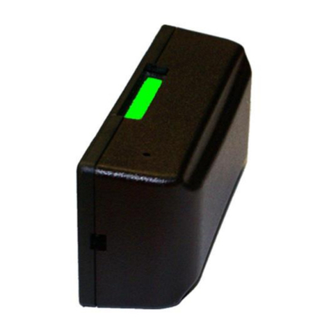
Sen Source TB12 Series User manual

PC-TB12-Series People Counter
Non-Directional Wireless Sensor
SenSource, Inc. • Youngstown, OH U.S.A.
www.sensourceinc.com • 800.239.1226
Rev. 2/20/2013 1

PC-TB12-Series People Counter Non-Directional Wireless Sensor
SenSource, Inc. • Youngstown, OH U.S.A.
www.sensourceinc.com • 800.239.1226
2Rev. 2/20/2013
TA B L E O F CO N T E N T S
Table of Contents ........................................................................................................................................................................................................................2
INTRODUCTION...........................................................................................................................................................................................................................3
Product Overview..................................................................................................................................................................................................................3
Features .................................................................................................................................................................................................................................3
Components...........................................................................................................................................................................................................................3
Getting Started.......................................................................................................................................................................................................................3
Caution...................................................................................................................................................................................................................................3
HARDWARE OVERVIEW...............................................................................................................................................................................................................4
RX Unit Functions ...................................................................................................................................................................................................................4
TX Unit Functions ...................................................................................................................................................................................................................4
Ambient Light Diffuser ...........................................................................................................................................................................................................4
Batteries.................................................................................................................................................................................................................................4
Hardware Diagram .................................................................................................................................................................................................................5
Sensor Specifications..............................................................................................................................................................................................................5
Memory..................................................................................................................................................................................................................................5
PREREQUISITES AND REQUIREMENTS.........................................................................................................................................................................................6
Hardware ...............................................................................................................................................................................................................................6
Software.................................................................................................................................................................................................................................6
Networking- TB12-R Non-Radio .............................................................................................................................................................................................6
Networking- TB12N-WR Wifi Version 802.11b/g/n................................................................................................................................................................6
Networking- TB12N-9R 900 Mhz............................................................................................................................................................................................6
SETUP AND CONFIGURATION .....................................................................................................................................................................................................7
Software Installation ..............................................................................................................................................................................................................7
TB12-R Non-Radio RX Unit Configuration (Unit with the LCD display) ...................................................................................................................................7
TB12-R Non-Radio TX Unit Configuration...............................................................................................................................................................................8
TB12N-WR (Wifi) BATTERY-LIFE CONSIDERATIONS ................................................................................................................................................................9
TB12N-WR (Wifi) Accuracy CONSIDERATIONS .......................................................................................................................................................................9
TB12N-WR Wifi RX Unit Configuration (unit with the LCD display) ......................................................................................................................................10
TB12N-WR Wifi TX Unit Configuration .................................................................................................................................................................................11
TB12N-9R 900Mhz RX Unit Configuration (unit with the LCD display) .................................................................................................................................12
TB12N-9R 900Mhz TX Unit Configuration ............................................................................................................................................................................13
INSTALLATION...........................................................................................................................................................................................................................14
Hardware .............................................................................................................................................................................................................................14
Side-Firing (Door/Frame Mount).....................................................................................................................................................................................14
Front-Firing (Opposing Wall Mount) ...............................................................................................................................................................................14
Mounting Overview..............................................................................................................................................................................................................14
Back-Plate Direction .............................................................................................................................................................................................................15
Side-Firing .......................................................................................................................................................................................................................15
Non-Side Specific.............................................................................................................................................................................................................15
Front-Firing......................................................................................................................................................................................................................15
RX Unit on Right ..............................................................................................................................................................................................................15
Front-Firing......................................................................................................................................................................................................................15
RX Unit on Left ................................................................................................................................................................................................................15
INTEGRATION............................................................................................................................................................................................................................16
LIMITED WARRANTY .................................................................................................................................................................................................................17

PC-TB12-Series People Counter
SenSource, Inc. • Youngstown, OH U.S.A.
www.sensourceinc.com • 800.239.1226
Rev. 2/20/2013 3
INTRODUCTION
PR O D U C T OV E R V I E W
The PC-TB12-Series is a complete, self-contained, battery operated people counter. This system consists of a photoelectric
infrared beam transmitter and receiver, which can operate up to 30 ft apart in front-firing or side-firing modes. The counter
will increment as the invisible IR beam is broken, regardless of the direction of traffic. The on-board memory stores data
that can be extracted. This counter provides an easily installed, comprehensive network solution for local and central data
collection.
The PC-TB12-Series sensors are versatile and come in three varieties to suit your needs. The TB12-R is a non-radio sensor
that does not require a network, data is extracted via USB. The TB12N-WR is a Wifi sensor that easily integrates with any
802.11 b/g/n network. The TB12N-9R is a 900Mhz sensor that integrates with a 900Mhz sensor server making it an ideal
wireless solution that does not require a Wifi network.
FE A T U R E S
Three versions to suit your needs USB, Wifi, and 900 Mhz radio varieties.
Battery-powered sensor installs in minutes. (3.6V AA size lithium included).
6-digit LCD screen.
Integrated memory holds data for up to 128 days.
Dual firing: front-firing (opposing wall mount) or side-firing (door frame mount).
USB 2.0 allows easy configuration from any PC on all three sensor types.
Adjustable high/low sensing range to extend battery life of sensor.
Sensor utility software easily configures your sensors settings.
CO M P O N E N T S
Systems are custom built; these are components of a standard build.
One transmitter- TX unit and one receiver –RX unit
Installation hardware
Two mounting plates
SenSource configuration utility software
Tool- Blue mini screwdriver
One USB programming cable
GE T T I N G ST A R T E D
Read the instruction manual: An understanding of through beam technology and sensor placement is crucial for
optimum accuracy.
Install SenSource software
Turn both sensors ON
Configure your sensors and verify network connectivity
Install mounting brackets
Mount sensors
CA U T I O N
Light: Ambient light may cause false counts. Use the provided rubber diffusers to reduce ambient light.
Impact/Shock: Heavy impact or shock may cause damage to hardware.
Tampering: Changes or modifications not expressly approved by SenSource will void the warranty.
Cleaning: Harsh cleaners, such as paint remover or benzene, may ruin the surface. Use a soft, wet cloth and mild
soap or detergent to clean displays and lenses.

PC-TB12-Series People Counter Non-Directional Wireless Sensor
SenSource, Inc. • Youngstown, OH U.S.A.
www.sensourceinc.com • 800.239.1226
4Rev. 2/20/2013
HARDWARE OVERVIEW
RX UN I T FU N CT I O N S
Reading the current counts: When the IR beam is broken the LCD display on the RX unit will list the current
count value.
To view the counts without breaking the beam briefly tap the service button on the RX unit. The LCD counter will
then display the current total count as well as an F or S, indicating which mode (front- or side-firing) is being
used.
Clearing the LCD Counter: The counter may be reset by pressing the service button until the counter indicates a
zero count. The display will read new batt when it is reset to default.
Configuration Mode: When plugged into a PC via USB the LCD display should read Config. The RX unit must be
placed in configuration mode to change settings with the sensor utility software.
TX UN I T FU N C T I O N S
Indicate Mode: Briefly tapping the service button will allow the TX unit to indicate the programmed mode of
operation. The LED will flash 1 to 4 times.
o1 flash = Front-Firing Low Power
o2 flashes = Front-Firing High Power
o3 Flashes = Side-Firing Low Power
o4 Flashes = Side-Firing High Power
Configuration Mode: When plugged into a PC via USB the LCD display should read Config. The TX unit must be
placed in configuration mode to change settings with the sensor utility software.
AM B I E N T LI G H T DI F F U S E R
The RX unit with the LCD display is shipped with
two rubber lens covers inserted in the beam-
receiving openings. These lens covers are used to
reduce ambient light interference.
If you remove the rubber lens covers (not
recommended), store covers until system is
successfully installed.
BA T T E R I E S
The PC-TB12-Series sensors require four 3.6V Lithium AA batteries. NOTE: Older models used standard 1.5V lithium
batteries. Check your battery compartment to verify proper battery type.
To replace the batteries disconnect the sensor from the back-plate.
Turn sensors OFF.
Remove the battery compartment lid by unscrewing the cover.
Replace both batteries in the TX unit. NOTE The batteries go in the same directions ++.
Replace both batteries in the RX unit. NOTE The batteries go in the same directions ++.
Standard 1.5V Lithium AA batteries are NOT supported.
Do not over torque screws you may strip the threads in the enclosure.
Battery life: It is recommended to change your batteries every six months to ensure system optimization.

PC-TB12-Series People Counter
SenSource, Inc. • Youngstown, OH U.S.A.
www.sensourceinc.com • 800.239.1226
Rev. 2/20/2013 5
HA R D W A R E DI A G R A M
Figure 1
SE N S O R SP E C I F I C A T I O N S
MIN
TYP
MAX
Infra-Red Beam Range*
-
10’
30’
Radio Transmit RangeTB12N-WR (Wifi)**
-
40-60’
100’
Radio Transmit RangeTB12N-9R (900Mhz)**
500’
1000’
Battery Life***
6 mo.
1 yr.
2 yr.
* Ambient light may cause false counts.
**Radio transmit range is determined by many factors. Max refers to line of sight with no obstructions. Walls, going around
corners, metal, and other radio frequencies can affect the range of your device.
***Battery life varies due to many factors including wireless network settings, use/traffic, and sensor configuration.
SenSource recommends a regular maintenance program of new batteries every six months to ensure system optimization.
Battery Type
(Qty 4) 3.6v AA Lithium, 2x Each
Older sensors used1.5V AA size batteries are no longer supported.
Enclosure -Indoor Use Only
2” x 4.3” x 1.2”, ABS (CYCOLAC) Plastic
ME M O R Y
Data retention is determined by the logging period set in the sensor utility software.
Logging Period (minutes)
Data Retention (days)
2
4
5
10
10
21
15
32
20
42
30
64
60
128

PC-TB12-Series People Counter Non-Directional Wireless Sensor
SenSource, Inc. • Youngstown, OH U.S.A.
www.sensourceinc.com • 800.239.1226
6Rev. 2/20/2013
PREREQUISITES AND REQUIREMENTS
HA R D W A R E
Basic hand tools are required to mount the sensors on door frames or opposing walls. Mounting hardware included.
SO F T W A R E
Windows Operating System
XP, Server 2003, Vista, Server 2008, 7
Processor - 32 bit
1.5 GHz Intel Pentium IV or AMD Athalon XP
Processor - 64 bit
2.4 GHz Intel Core 2 Duo or AMD Turion
Disk Space (stand-alone)
75 MB
Disk Space (with Sequel 2008 Express R2)
2GB (4GB max)
Memory - 32 bit
1GB
Memory - 64 bit
2GB
.Net 3.5 Service Pack 1
Net 4.0
Windows Powershell 1.0
Windows Installer 4.5
Windows Installer 4.5 update
Java
NE T W O R K I N G -TB1 2- R NON-RA D I O
Network independent, no networking required.
NE T W O R K I N G -TB1 2N -WR WI F I VE R S I O N 8 02 .11 B/G/N
Security Set Identifier: (required).
IP Address: (required) Can be set statically (recommended) or dynamically by DHCP.
Authentication Type: (required) WEP-128, WPA-PSK, or WPA2-PSK.
Phrase: (required).
Destination or Hostname IP: (required) You must know the IP of the destination address or dedicated machine
with SenSource software installed on to push to NOTE: If you are using our hosted solution then SenSource will
provide the destination address.
Port 6767 UDP: (required) The sensors communicate over port 6767 UDP, in some cases ports have to be open for
in/out traffic and in some cases port forwarding is required.
NE T W O R K I N G -TB1 2N -9R 90 0 MHZ
IP Address: Can be set statically (recommended) (required).
Subnet Mask: (required).
Gateway: (required).
Port 1000: The sensors communicate over port 1000 using TCP, in some cases ports have to be open for in/out
traffic and in some cases port forwarding is required.
SMTP Server Address: (required)
PCW-SSRX4.9 sensor server ( purchased separately)( required)

PC-TB12-Series People Counter
SenSource, Inc. • Youngstown, OH U.S.A.
www.sensourceinc.com • 800.239.1226
Rev. 2/20/2013 7
SETUP AND CONFIGURATION
SO F T W A R E IN S T A L L A T I O N
1. Insert the installation CD into the disk drive bay.
2. Run index.htm or Open to view files.
3. Active Content: Internet Explorer may ask you if you would like to run active content. Choose Yes.
4. You can also launch the software by accessing your CD drive via My Computer.
5. On the software install home page click here link to install sensor utility software.
6. IE may ask you to confirm do you want to run or save SensorUtilitySetup. Choose Run or Save to the appropriate
location.
7. Follow the installation wizard instructions to finish your install.
8. NOTE: If you are having trouble connecting via USB install the driver located on the cd named CDM20814.exe.
SEN SO R CON F IGU R A TI ON
T B1 2 -R NON-RA D I O RX UN I T CO N F I G U R A T I O N (UN I T W I T H T H E LC D D I S P L A Y )
Power on the RX unit by using the small blue screwdriver to slide the power ON/OFF switch. The LCD display will briefly
display HELLO when the sensor is first turned. Connect the RX unit to the computer via the USB cable. You are now in
configuration mode. The LCD screen will read Config. Note: The sensor will not broadcast data while in configuration
mode.
Launch the Sensor Utility software, sometimes called the WIFI IR Beam Setup. Select Options (Figure 2) from the top of the
menu, and then choose Radio Type, next select None.
Verify that the status bar at the bottom of the window reads Found Counter
If it reads Looking for Sensor or USB Programmer…, then the software cannot find the sensor. Verify that the
USB cable is connected to sensor and computer, the LCD screen on the sensor should say Config.
If you are still experiencing problems reseat your connections and try again.
If you are still experiencing problems install the USB driver named CDM20814_Setup.exe located on the
software cd.

PC-TB12-Series People Counter Non-Directional Wireless Sensor
SenSource, Inc. • Youngstown, OH U.S.A.
www.sensourceinc.com • 800.239.1226
8Rev. 2/20/2013
Click the Retrieve button. Upon successful retrieval an indication window will say Sensor Parameters Retrieved. Click OK.
In the sensor tab choose your logging interval (one hour logging period is recommended). In the count parameters
section choose front or side mode. Click update. A confirmation box will appear to save a programming profile, choose
save Y/N. You do not have to save if you do not want to.
T B1 2 -R NON-RA D I O TX UN I T CO N F I G U R A T I O N
Power on the TX unit by using the small blue screwdriver to slide the power ON/OFF switch. The LCD display will briefly
display HELLO when the sensor is first turned. Connect the RX unit to the computer via the USB cable. You are now in
configuration mode. The LCD screen will read Config. Note: The sensor will not broadcast data while in configuration
mode.
In the count parameters section select either front or side firing. Select either high or low power to adjust the intensity of
the infrared beam. High power is recommended for most applications. Click update. A confirmation box will appear to save
a programming profile, choose save Y/N. You do not have to save if you do not want to.

PC-TB12-Series People Counter
SenSource, Inc. • Youngstown, OH U.S.A.
www.sensourceinc.com • 800.239.1226
Rev. 2/20/2013 9
TB12N-WR (WI F I )CO NF I GU R A T I ON A N D BE S T PR A C T IC E S
TB 1 2N - WR (WI F I )BA TTERY -L IFE C ON SI DERAT IO NS
1. Set the sensor to a static IP address rather than using a dynamic (DHCP) IP address. The radio must remain on for a
longer period of time to request and receive a dynamic address from the DHCP server.
2. Set the wireless access point to a specific channel, and program the sensor to connect on that particular channel.
If Auto-Channel must be used, limit the channels to 1, 6, and 11, and set the sensor to only search those three
channels. The more channels that the sensor must scan, the faster the batteries will be depleted.
3. If your location has more than one wireless access point that use the same SSID, set each access point to a specific
channel, and program the sensor to connect only to the channel of the closest access point. If multiple access
points have the same SSID and are using auto-channel, the sensor may bounce between multiple access points,
causing the radio to remain on for a longer period of time, depleting the batteries.
4. TB12-Series sensors should not be used for near-real-time data collection. Use the longest possible transmit
period. Although the sensor is able to transmit data at intervals as small as two minutes, it is best to use a 6-8 hour
(or longer) transmit interval to conserve battery power. (Keep in mind that logging is independent of the transmit
interval. For example, log data every 15 minutes, and send it every 8 hours. Although you must wait longer to
receive the data, you may still view the counts in smaller time intervals.)
5. Verify that you have adequate signal strength using the Wi-Fi Setup Utility. The sensors may have difficulty
connecting to the access point with signal strengths below -63 DbM.
6. Verify that sensors are aligned, and in the proper firing and power modes for the application. If the RX unit has
difficulty ‘seeing’ the beam from the TX unit, it will try to re-synchronize, which requires more power from the
batteries.
7. Verify that the following settings are DISABLED in the Advanced Options of the Wi-Fi Setup Utility:
a. DHCP Caching
b. ARP Caching
c. DNS Caching
d. Allow Channels 12 and 13 (If possible)
8. When performing a change of batteries, after swapping the batteries press and hold the service button next to the
USB port for approximately 10 seconds, or until the message NEW BATT is displayed on the LCD counter, release
the service button and tap the service button once more to force a new data transmission and service signal from
the sensors. (Use 3.6 Volt Lithium Batteries Only)
TB 1 2N - WR (WI F I )AC CU R A C Y C ON SI DER ATION S
1. Mounting Height –To avoid receiving multiple counts caused by swinging arms and legs, it is recommended that
the sensors be mounted at a height between 48 and 54 inches. If the sensors must be lowered to count children,
the arms and/or legs of adults may cause false counts.
2. Couples and Groups –Break-Beam sensors are most accurate when traffic is single-file, and going in one direction
at a time. If multiple people break the beam at the same time, the sensor will only count one. All though these
sensors are capable of spanning distances of up to 40 ft., it is important to remember that as you increase the
distance, and allow larger crowds to pass through at the same time, you decrease your accuracy.
3. TB12-Series sensors are non-directional sensors, and do not provide separate counts for entries and exits. If people
will enter and exit through the same sensors, counts must be divided by two.
4. IR Interference –Sunlight, automatic door sensors, night-vision security cameras, and other sources of infrared
light near the sensor may cause false or missed counts. Avoid mounting sensors within close proximity to a source
of infrared light. If sensors will be used in an area that receives full sun, the sensors should be tested in the desired
mounting location, in full sun, prior to permanently mounting them on the walls or door frames. Use the ambient
light diffuser grommets.

PC-TB12-Series People Counter Non-Directional Wireless Sensor
SenSource, Inc. • Youngstown, OH U.S.A.
www.sensourceinc.com • 800.239.1226
10 Rev. 2/20/2013
TB1 2N - WR WI F I RX UN I T CO N F I G U R A T I O N (U NI T W IT H T HE LC D D I S P L A Y )
Power on the RX unit by using the small blue screwdriver to slide the power ON/OFF switch. The LCD display will briefly
display HELLO when the sensor is first turned. Connect the RX unit to the computer via the USB cable. You are now in
configuration mode. The LCD screen will read Config. Note: The sensor will not broadcast data while in configuration
mode. Launch the Sensor Utility software, sometimes called the WIFI IR Beam Setup. Select Options (Figure 2) from the
top of the menu, and then choose Radio Type, next select WiFi 802.11b/g.
Verify that the status bar at the bottom of the window reads Found Counter
If it reads Looking for Sensor or USB Programmer…, then the software cannot find the sensor. Verify that the
USB cable is connected to sensor and computer, the LCD screen on the sensor should say Config.
If you are still experiencing problems reseat your connections and try again.
If you are still experiencing problems install the USB driver named CDM20814_Setup.exe located on the
software cd.
Upon successful retrieval an indication window will say Sensor Parameters Retrieved. Click OK.
It is recommended to use the best practices settings described above.
In the Network tab the following fields need configured.
IP Address- static or dynamic
Subnet Mask
Gateway
DNS (optional)
SSID
Channel: Auto Find is recommended
Authentication Type: WEP-128, WPA-PSK, or
WPA2-PSK
Phrase (static addressing only)
Port 6767 is default communication port
In the Sensor tab the following fields need configured.
Transmit period
Logging Period
Direction: Front or Side
Click update. A confirmation box will appear to save a programming profile, choose save Y/N. You do not have to save if
you do not want to.

PC-TB12-Series People Counter
SenSource, Inc. • Youngstown, OH U.S.A.
www.sensourceinc.com • 800.239.1226
Rev. 2/20/2013 11
TB1 2N - WR WI F I TX UN I T CO N F I G U R A T I O N
Power on the TX unit by using the small blue screwdriver to slide the power ON/OFF switch. The LCD display will briefly
display HELLO when the sensor is first turned. Connect the RX unit to the computer via the USB cable. You are now in
configuration mode. The LCD screen will read Config. Note: The sensor will not broadcast data while in configuration
mode.
In the count parameters section select either front or side firing. Select either high or low power to adjust the intensity of
the infrared beam. High power is recommended for most applications. Click update. A confirmation box will appear to save
a programming profile, choose save Y/N. You do not have to save if you do not want to.

PC-TB12-Series People Counter Non-Directional Wireless Sensor
SenSource, Inc. • Youngstown, OH U.S.A.
www.sensourceinc.com • 800.239.1226
12 Rev. 2/20/2013
TB 1 2N - 9R 900MH Z RX UN I T CO N F I G U R A T I O N (U N I T W I T H T H E LC D D I S P LA Y )
Power on the RX unit by using the small blue screwdriver to slide the power ON/OFF switch. The LCD display will briefly
display HELLO when the sensor is first turned. Connect the RX unit to the computer via the USB cable. You are now in
configuration mode. The LCD screen will read Config. Note: The sensor will not broadcast data while in configuration
mode. Launch the Sensor Utility software, sometimes called the WIFI IR Beam Setup. Select Options (Figure 2) from the
top of the menu, and then choose Radio Type, next select Digi XBee:900/2.4/Zigbee.
Verify that the status bar at the bottom of the window reads Found Counter
If it reads Looking for Sensor or USB Programmer…, then the software cannot find the sensor. Verify that the
USB cable is connected to sensor and computer, the LCD screen on the sensor should say Config.
If you are still experiencing problems reseat your connections and try again.
If you are still experiencing problems install the USB driver named CDM20814_Setup.exe located on the
software cd.
Upon successful retrieval an indication window will say Sensor Parameters Retrieved. Click OK.
It is recommended to use the best practices settings described above in the Wifi section for transmit period.
In the Sensor tab the following fields need configured.
Transmit period
Logging Period
Direction: Front or Side
Click update. A confirmation box will appear to save a programming profile, choose save Y/N. You do not have to save if
you do not want to.

PC-TB12-Series People Counter
SenSource, Inc. • Youngstown, OH U.S.A.
www.sensourceinc.com • 800.239.1226
Rev. 2/20/2013 13
TB 1 2N - 9R 900MH Z TX UN I T CO N F I G U R A T I O N
Power on the TX unit by using the small blue screwdriver to slide the power ON/OFF switch. The LCD display will briefly
display HELLO when the sensor is first turned. Connect the RX unit to the computer via the USB cable. You are now in
configuration mode. The LCD screen will read Config. Note: The sensor will not broadcast data while in configuration
mode.
In the count parameters section select either front or side firing. Select either high or low power to adjust the intensity of
the infrared beam. High power is recommended for most applications. Click update. A confirmation box will appear to save
a programming profile, choose save Y/N. You do not have to save if you do not want to.

PC-TB12-Series People Counter Non-Directional Wireless Sensor
SenSource, Inc. • Youngstown, OH U.S.A.
www.sensourceinc.com • 800.239.1226
14 Rev. 2/20/2013
INSTALLATION
HA R D W A R E
SIDE-FIRING (DOOR/FRAME MOUNT)
FRONT-FIRING (OPPOSING WALL MOUNT)
MO U N T I N G OV E R V I E W
1. The sensors must be mounted so that they are no more than 40
feet apart (high-power mode) or 12 feet apart (low-power mode).
2. The sensors should be mounted 3-4 feet off the ground to count
all traffic, or 4-5 feet off the ground to count only adult traffic.
3. The mounting surface should be sturdy in order to prevent
misalignment from bumping into either the sensor or mounting
bracket.
4. A tape measure is accurate enough to mount the sensors level
enough so they can see each other.
5. The image on the right provides examples of both correct and
incorrect mounting for either Side-Firing or Front-Firing
configurations.
6. Door swing must be taken into consideration before mounting
the sensors (especially true for side-firing mode, where sensors are
typically mounted on the doorframe). Ensure that the door does not
break the beam when it opens or closes.

PC-TB12-Series People Counter
SenSource, Inc. • Youngstown, OH U.S.A.
www.sensourceinc.com • 800.239.1226
Rev. 2/20/2013 15
Side-Firing (Door/Frame Mount)
Front-Firing (Opposing Wall Mount)
BA C K -PL A T E DI R E CT I O N
1. Mount the sensor back-plates to the desired surface (before attaching the sensor units).
If the LCD screen is to be used, the orientation of the back-plate is critical.
Determine if the sensors will be used in Front- or Side-Firing mode, and if the RX unit is to be mounted on the
left or right.
SIDE-FIRING
NON-SIDE SPECIFIC
FRONT-FIRING
RX UNIT ON RIGHT
FRONT-FIRING
RX UNIT ON LEFT
2. Power on the RX and TX sensor units (if you have not done so already)
by using the small, blue screwdriver to move the power ON/OFF
switch.
The ON/OFF switches will not be accessible once the sensors are
mounted.
3. Attach the sensors to the back-plates.
Insert the dual tabs at point Ainto the receptacles on the back of
the sensor.
oThe sensor must be initially tilted at an angle, as shown in
the image on the right.
Once the tabs are inserted, tilt the other end of the sensor
toward the back-plate –inserting the larger, single tab at point B
into the receptacle on the back of the sensor.
When the tabs are in place, slowly apply some force to snap the
senor onto the back-plate.
Note: To remove the sensors from the back-plate use the small, blue
screwdriver to push on the locking tab in the small hole at point C, while
pulling slightly on the sensor to release it from the back-plate.

PC-TB12-Series People Counter Non-Directional Wireless Sensor
SenSource, Inc. • Youngstown, OH U.S.A.
www.sensourceinc.com • 800.239.1226
16 Rev. 2/20/2013
INTEGRATION
1. After installing the sensor utility software
2. Send a service signal from the RX unit by tapping the service button on the RX (located to the right of the USB port)
until the LED indication flashes briefly
3. The sensor will show up in the unassigned category in your System Manager software
4. For more information on System Manager, Vea, or reports please visit our Knowledge Base at SenSource.com
System Manager is used to define regions, districts, and facilities by breaking down your
organization into a tree that interfaces with MS SQL, the Service Configuration Utility, and Vea View.
Service Configuration Utility controls the service that is required for the applications to function.
Our service is named System_Manager_Service.
Vea View is a robust tool that allows you to see business metrics that combine multiple data
sources such as point of sale and customer traffic. Reporting can be automated and sent to your
recipient group.
The Sensor Utility and WIFI IR beam setup tool are named different, but are the same tool. The
programs are used with our TB-12R series sensors. Either tool can be used for all three model types
Wifi, 900 Mhz, and non-radio.
The applications allow you to plug your sensor in via USB and modify your sensor settings. You
can adjust network settings along with some network troubleshooting tools. You can also adjust
infrared beam settings. Also, you can adjust your logging time bins.
Server Manager software is used in conjunction with sensor servers. Server manager allows you
to define regions, districts, and facilities by breaking down your organization into a tree. Server
manager is stand-alone, no SQL required to connect your applications. You can generate reports
right from the server manager software.

PC-TB12-Series People Counter
SenSource, Inc. • Youngstown, OH U.S.A.
www.sensourceinc.com • 800.239.1226
Rev. 2/20/2013 17
LIMITED WARRANTY
HARDWARE: SenSource, Inc. warrants to the original end user ("Customer") that this product will be free from defects in workmanship and materials
(under normal use) for one year from date of shipment from SenSource, Inc. or its authorized reseller. SenSource, Inc.'s sole obligation under this express
warranty shall be (at SenSource, Inc.'s option and expense) to replace the product or part with a comparable product or part, repair the product or part, or
—if neither repair nor replacement is reasonably available —SenSource, Inc. may (in its sole discretion) refund to Customer the purchase price paid for
the product or part. Replacement products or parts may be new or reconditioned. SenSource, Inc. warrants any replaced or repaired product or part, and
any hardware upgrade to which Customer is entitled under an agreement between Customer and SenSource, Inc. for the remainder of the original
warranty period. All products or parts, returned for replacement, become the property of SenSource, Inc.
SOFTWARE: SenSource, Inc. warrants to Customer that provided software will perform in substantial conformance to their program specifications for a
period of ninety days from the date of original purchase from SenSource, Inc. or its authorized reseller. SenSource, Inc. warrants the media-containing
software against failure during the warranty period. No updates are provided. SenSource, Inc. does not provide any warranty for any third-party software
that is licensed to Customer by the third party. SenSource, Inc.'s sole obligation, with respect to this express warranty, shall be (at SenSource, Inc.'s
discretion) to refund the purchase price paid by Customer for any defective software product, or to replace any defective media with software, which
substantially conforms to applicable specifications. SenSource, Inc. makes no warranty or representation that its software products will meet Customer's
requirements, will work in combination with any hardware or software products provided by third parties, that the operation of the software products will
be uninterrupted or error free, or that all defects in the software products will be corrected.
OBTAINING WARRANTY SERVICE: Customer must contact SenSource, Inc. Technical Support (PH: 800-239-1226 option 3 or E-Mail:
support@sensource.biz) within the applicable warranty period to obtain warranty service. Dated proof of original purchase from SenSource, Inc. or its
authorized reseller is required. SenSource, Inc. is not responsible for Customer products or parts received without a warranty service authorization (or
Return Materials Authorization, “RMA”). In the United States, SenSource, Inc. may ship a replacement product or part prior to receiving the original
product or part ("advance exchange"). If advance exchange is not available, then the repaired product or part will be shipped as soon as reasonably
possible. Repaired or replacement products will be shipped to the Customer at SenSource, Inc.'s expense. The repair and replacement process for products
or parts in locations outside of the United States will vary depending on Customer's location. All materials are to be shipped to the following address only
after Customer obtains a Return Materials Authorization (RMA): SenSource, Inc., Attn: Returns Department, 3890 Oakwood Ave, Youngstown, OH 44515.
Products or parts shipped by Customer to SenSource, Inc. must be sent prepaid and packaged appropriately for safe shipment. SenSource, Inc.
recommends insuring the package, or shipping by a method that provides for tracking of the package. When an advance exchange is provided, SenSource
will charge customer for the replacement items and issue credit when the faulty items are received and evaluated.
WARRANTIES EXCLUSIVE: IF A PRODUCT DOES NOT OPERATE AS WARRANTED ABOVE, CUSTOMER'S SOLE REMEDY FOR BREACH OF THAT WARRANTY
SHALL BE REPLACEMENT OR REPAIR OF THE PRODUCT OR PART, OR REFUND OF THE PURCHASE PRICE PAID (AT SENSOURCE, INC.'S OPTION). TO THE FULL
EXTENT ALLOWED BY LAW, THE FOREGOING WARRANTIES AND REMEDIES ARE EXCLUSIVE, AND ARE IN LIEU OF ALL OTHER WARRANTIES, TERMS, OR
CONDITIONS. EXPRESS OR IMPLIED, EITHER IN FACT OR BY OPERATION OF LAW, STATUTORY, OR OTHERWISE, INCLUDING WARRANTIES, TERMS, OR
CONDITIONS OF MERCHANTABILITY, FITNESS FOR A PARTICULAR PURPOSE, SATISFACTORY QUALITY, CORRESPONDENCE WITH DESCRIPTION, AND NON-
INFRINGEMENT —ALL OF WHICH ARE EXPRESSLY DISCLAIMED. SENSOURCE, INC. NEITHER ASSUMES NOR AUTHORIZES ANY OTHER PERSON TO ASSUME
FOR IT ANY OTHER LIABILITY IN CONNECTION WITH THE SALE, INSTALLATION, MAINTENANCE, OR USE OF ITS PRODUCTS. SENSOURCE, INC. SHALL NOT BE
LIABLE UNDER THIS WARRANTY IF ITS TESTING AND EXAMINATION DISCLOSE THAT THE ALLEGED DEFECT OR MALFUNCTION IN THE PRODUCT DOES NOT
EXIST OR WAS CAUSED BY CUSTOMER'S, OR ANY THIRD PERSON'S, MISUSE, NEGLECT, IMPROPER INSTALLATION OR TESTING, UNAUTHORIZED ATTEMPTS
TO OPEN, REPAIR, OR MODIFY THE PRODUCT, OR ANY OTHER CAUSE BEYOND THE RANGE OF THE INTENDED USE, OR BY ACCIDENT, FIRE, LIGHTNING,
POWER CUTS OR OUTAGES, OTHER HAZARDS, OR ACTS OF GOD. THIS WARRANTY DOES NOT COVER PHYSICAL DAMAGE TO THE SURFACE OF THE
PRODUCT, INCLUDING CRACKS OR SCRATCHES ON THE LCD DISPLAY OR OUTSIDE CASING. THIS WARRANTY DOES NOT APPLY WHEN THE MALFUNCTION
RESULTS FROM THE USE OF THIS PRODUCT IN CONJUNCTION WITH ACCESSORIES, OTHER PRODUCTS, OR ANCILLARY OR PERIPHERAL EQUIPMENT, AND
SENSOURCE, INC. DETERMINES THAT THERE IS NO FAULT WITH THE PRODUCT ITSELF. THIS WARRANTY DOES NOT APPLY TO ANY MALFUNCTION OR
FAILURE OF THE PRODUCT OR PART DUE TO ANY COMMUNICATION SERVICE CUSTOMER MAY SUBSCRIBE TO FOR USE WITH THE PRODUCT.
LIMITATION OF LIABILITY: TO THE FULL EXTENT ALLOWED BY LAW, SENSOURCE, INC. ALSO EXCLUDES (FOR ITSELF AND ITS SUPPLIERS) ANY LIABILITY,
WHETHER BASED IN CONTRACT OR TORT (INCLUDING NEGLIGENCE), FOR INCIDENTAL, CONSEQUENTIAL, INDIRECT, SPECIAL, OR PUNITIVE DAMAGES OF
ANY KIND, OR FOR LOSS OF REVENUE OR PROFITS, LOSS OF BUSINESS, LOSS OF INFORMATION OR DATA, OR OTHER FINANCIAL LOSS ARISING OUT OF OR
IN CONNECTION WITH THE SALE, INSTALLATION, MAINTENANCE, USE, PERFORMANCE, FAILURE, OR INTERRUPTION OF THIS PRODUCT, EVEN IF
SENSOURCE, INC. OR ITS AUTHORIZED RESELLER HAS BEEN ADVISED OF THE POSSIBILITY OF SUCH DAMAGES, AND LIMITS ITS LIABILITY TO REPLACEMENT,
REPAIR, OR REFUND OF THE PURCHASE PRICE PAID AT SENSOURCE, INC.’S OPTION. THIS DISCLAIMER OF LIABILITY FOR DAMAGES WILL NOT BE AFFECTED
IF ANY REMEDY PROVIDED HEREIN SHALL FAIL OF ITS ESSENTIAL PURPOSE.
DISCLAIMER: Some countries, states, or provinces do not allow the exclusion or limitation of implied warranties, or the limitation of incidental or
consequential damages for certain products supplied to consumers, or the limitation of liability for personal injury. Therefore, the above limitations and
exclusions may be limited in their application to Customer. When the implied warranties are not allowed to be excluded in their entirety, they will be
limited to the duration of the applicable written warranty. This warranty gives Customer specific legal rights, which may vary depending on local law.
GOVERNING LAW: This Limited Warranty shall be governed by the laws of the State of Ohio, U.S.A., and by the laws of the United States, excluding their
conflicts of laws principles. The United Nations Convention on Contracts for the International Sale of Goods is hereby excluded in its entirety from
application to this Limited Warranty.
RESTOCKING POLICY: Items in good condition may be returned within 30 days of shipment at no charge to the Customer (not including shipping charges).
A pre-approved Returned Materials Authorization (RMA) must accompany returned merchandise. Items returned will be inspected for damage and
Customer will be notified of credit approval. Restocking fees will apply to items returned beyond 30 days and may vary with each product.
FRM-1050 / 2010-02-09
Table of contents
Other Sen Source Accessories manuals
Popular Accessories manuals by other brands
WiT
WiT WT901BLE user manual

Thermo Scientific
Thermo Scientific 61-12C Operating and service manual
Forma Scientific
Forma Scientific 3950 manual
Opus
Opus BWM 180 operating instructions

PCB Piezotronics
PCB Piezotronics M102A14 Installation and operating manual

Dorner
Dorner 2200 series Installation, maintenance & parts manual
