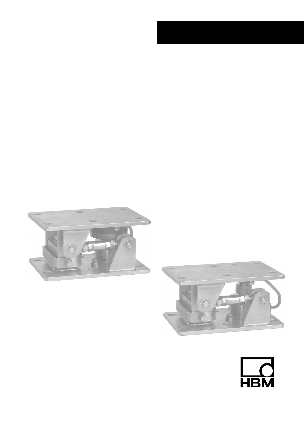
HBM RTN/M2 Series User manual

RTN/M2LBR / RTN/M2LB
RTN/M2LAR / RTN/M2LA
A1867-2.0 en/de/fr/es
Weighing modules
Wägemodule
Modules de pesage
Módulos de pesaje
RTN/M2...
Mounting Instructions
Montageanleitung
Notice de montage
Instrucciones de montaje

English Page 3 - 24.................................................
Deutsch Seite 25 - 46...............................................
Français Page 47 - 68...............................................
Español Página 69 - 89.............................................

3
RTN/M2
A1867-2.0 en/de/fr/es HBM
Contents Page
English
Safety Notes 4....................................................
1 General 7.....................................................
2 Mounting preparation 9........................................
3 Mounting 12....................................................
4 Dimensions (in mm; 1mm = 0.03937 inches) 15....................
5 Specifications of the RTN/M2L... weighing modules 21.............

RTN/M2
4
A1867-2.0 en/de/fr/esHBM
Safety Notes
In cases where a breakage would cause injury to persons or damage to
equipment, the user must take appropriate safety measures (such as fall
protection, overload protection, etc.).
It is essential to comply with the relevant accident prevention regulations. In
particular you should take into account the limit loads quoted in the specifica-
tions.
Use in accordance with the regulations
The weighing modules have beend designed for weighing applications. Use
for any additional purpose shall be deemed to be not in accordance with the
regulations.
In the interests of safety, the weighing modules should only be operated as
described in the Mounting Instructions. It is also essential to observe the
appropriate legal and safety regulations for the application concerned during
use. The same applies to the use of accessories.
The weighing modules are not safety elements within the meaning of its use
as intended. Proper and safe operation of this weighing module requires
proper transportation, correct storage, assembly and mounting and careful
operation and maintenance.
General dangers due to non‐observance of the safety instructions
The weighing modules correspond to the state of the art and are fail‐safe. The
weighing modules can give rise to residual dangers if they are inappropriately
installed and operated by untrained personnel.
Everyone involved with the installation, commissioning, maintenance or repair
of a weighing module must have read and understood the Mounting
Instructions and in particular the technical safety instructions.

5
RTN/M2
A1867-2.0 en/de/fr/es HBM
Residual dangers
The scope of supply and performance of the weighing modules covers only a
small area of weighing technology. In addition, equipment planners, installers
and operators should plan, implement and respond to the safety engineering
considerations of weighing technology in such a way as to minimise residual
dangers. Prevailing regulations must be complied with at all times. There must
be reference to the residual dangers connected with weighing technology.
In these mounting instructions residual dangers are pointed out using the
following symbols:
Symbol: CAUTION
Meaning: Possibly dangerous situation
Warns of a potentially dangerous situation in which failure to comply with
safety requirements could lead to damage to property and physical injury.
Symbol: NOTE
Refers to the fact that important information is being given about the product
or its use.
Symbol:
Meaning: CE mark
The CE mark signals a guarantee by the manufacturer that his product meets
the requirements of the relevant EC directives.

RTN/M2
6
A1867-2.0 en/de/fr/esHBM
Environmental conditions
CAUTION
In the context of your application, please note that all materials which release
chlorine ions will attack all grades of stainless steel and their welding seams.
In such cases the operator must take appropriate safety measures.
With environmental conditions that cannot be clearly defined, HBM recom-
mends to provide the load cells and weighing modules with a protective
coating which matches these conditions (after mounting) in order to prevent
the influence of aggressive media. Please take into account the resistance of
the cable material and the mounting parts.
Prohibition of own conversions and modifications
The weighing modules must not be modified from the design or safety
engineering point of view except with our express agreement. Any
modification shall exclude all liability on our part for any damage resulting
therefrom.
Qualified personnel
These weighing modules are only to be installed by qualified personnel strictly
in accordance with the specifications and with the safety rules and regulations
which follow. It is also essential to observe the appropriate legal and safety
regulations for the application concerned. The same applies to the use of
accessories.
Qualified personnel means persons entrusted with the installation, fitting,
commissioning and operation of the product who possess the appropriate
qualifications for their function.
Accident prevention
Although the specified brealing load is several times the full scale value, the
relevant accident prevention regulations from the trade associations must be
taken into consideration.

7
RTN/M2
A1867-2.0 en/de/fr/es HBM
1 General
HBM offers the RTN/M2(L)... weighing module for RTN load cells with max.
capacities of 1 t ... 33 t. The ”L” in the type designation signifies that the mod-
ule has been fitted with a stay rod. “A” signifies rubber‐metal bearing, “B”
stands for pendulum bearing.
Product types RTN/M2LA...
Order number Max. capacity
for load cell Material Version
1-RTN/M2LAR2.2T 1 t ... 2.2 t stainless steel WITH stay rod
1-RTN/M2AR2.2T WITHOUT stay rod
1-RTN/M2LAR4.7T 4.7 t stainless steel WITH stay rod
1-RTN/M2AR4.7T WITHOUT stay rod
1-RTN/M2LAR22T 10 t ... 22 t stainless steel WITH stay rod
1-RTN/M2AR22T WITHOUT stay rod
1-RTN/M2LA33T 33 t galvanized WITH stay rod
1-RTN/M2A33T WITHOUT stay rod
Product types RTN/M2LB...
Order number Max. capacity
for load cell Material Version
1-RTN/M2LBR4.7T/2 1 t ... 4.7 t stainless steel WITH stay rod
1-RTN/M2BR4.7T/2 WITHOUT stay rod
1-RTN/M2LBR22T 10 t ... 22 t stainless steel WITH stay rod
1-RTN/M2BR22T WITHOUT stay rod
1-RTN/M2LB33T 33 t galvanized WITH stay rod
1-RTN/M2B33T WITHOUT stay rod

RTN/M2
8
A1867-2.0 en/de/fr/esHBM
The weighing modules have been primarily designed for use in tank weighing.
As a rule, the weighing modules are equipped with adjustable limit stops that
limit horizontal movements, for example by wind forces or in mixer operation.
In addition, the modules are provided with a anti‐liftoff device which prevents
the tank from lifting off. However, ensure that the specified data (see chapter
5) are not exceeded.
The modules comprise a lower module plate for mounting on the basic
construction (foundations), a load cell dummy with load introduction elements
and the upper module plate for tank mounting. For load introduction into the
load cell, a rubber‐metal bearing (with RTN/M2LA) or a pendulum bearing
(with RTN/M2LB) is used which allows for horizontal shifting of the load ap-
plied. The weighing modules are completely fitted with a load cell dummy that
can be loaded, with a ground cable, and a securing device for transport.

9
RTN/M2
A1867-2.0 en/de/fr/es HBM
2 Mounting preparation
Caution:
The weighing modules are delivered completely assembled , however,
without a load cell. Instead of the load cell, a dummy has been assembled
into the weighing module, which is capable of taking up the specified loads.
Before the weighing module is mounted underneath the tank, vessel or silo,
check whether dummy replacement through the load cell will still be possible
even if the tank is placed on the weighing module. In order to effect the re-
placement, a suitable lifting device is necessary that is capable of lifting the
tank by at least 10 mm. Pipe connections mounted on the tank or the feed‐in
or discharge systems have to be vertically movable or separable.
NOTE
If this is not the case, the dummy must be replaced by an appropriate
RTN load cell already before the weighing module is mounted.
General mounting preparations
Ensure that the assembly/siting areas provided are clean, level and hori-
zontally aligned. Any askew positions can be compensated for, depending
on the assembly situation, for example by appropriate wedges and com-
pensation plates (weld in position) or by grinding down the assembly area.
However, module plates must not be ground down under any circum-
stances.
The foundations / basic construction and the connection of the
superstructure must be sufficiently rigid in order to avoid deformations (e.g.
deflections) under load.
In order to provide for fitting and assembly free from any constraining
forces, the mounting bores on the basic construction and the tank connec-
tion must be sufficiently aligned.
An even loading on the bearing points is to be sought. To this end, in par-
ticular for statically indefinite bearings, ensure that the height level setting
at the bearing points is correct (provide spacer plates, 5 x 1 mm included
in scope of delivery).
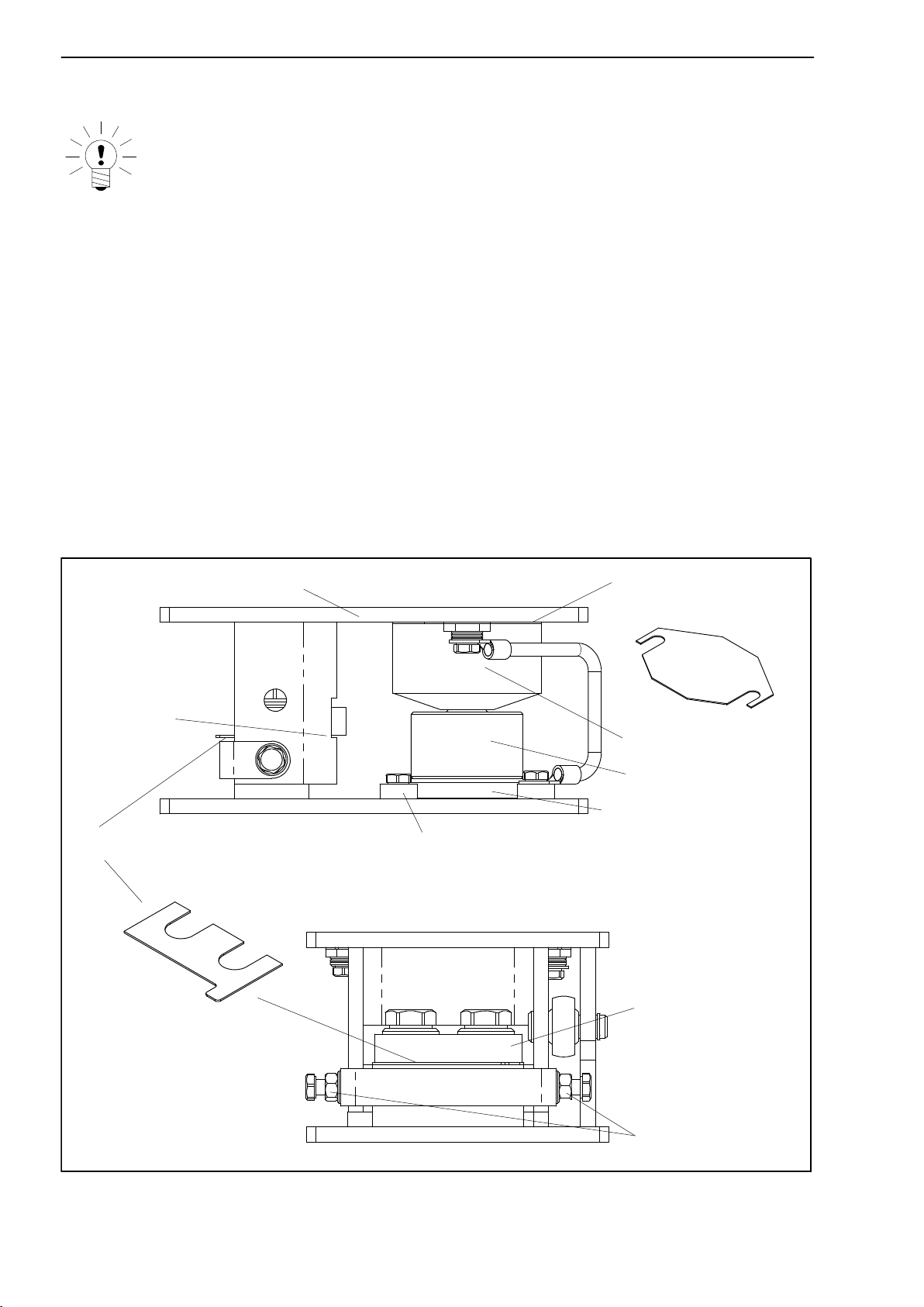
Undo transport protection device and stops, fit height adjustment plates
(dependent on maximum capacity, see Dimensions).

RTN/M2
10
A1867-2.0 en/de/fr/esHBM
How to use the enclosed grease tube
NOTE
Before fitting the load cell, the enclosed grease must be applied to the
upper thrust piece and to the underside of the pendulum bearing (with
RTN...B) in order to minimize friction between the inside surface of the
thrust piece and the load introduction element of the RTN load cell or
pendulum bearing.
Use of the spacer plates provided
The scope of delivery of the module includes 2 x 5 spacer plates. They are
used for the vertical adjustment of the module. Five plates max. are to be
fitted underneath the upper module plate, and five plates max. between the
base and the cross bracket of the anti‐liftoff device
Ensure that all screws are fitted with U‐washers.
5 plates max. for
height adjustment
5 plates max. for height adjustment
Upper module plate
Centering disc (only up
to 4.7 t max. capacity)
Lateral stops
Cross‐bracket
(Anti‐liftoff device)
Air gap: 1 mm
Mounting base (only up
to 4.7 t max. capacity)
Bearing
Dummy
Fig. 7.1: Fitting of the spacer plates with 4.7 t version

11
RTN/M2
A1867-2.0 en/de/fr/es HBM
5 plates max. for
height adjustment
5 plates max. for height adjustment
Upper module plate
Lateral stops
Cross‐bracket
(Anti‐liftoff device)
Air gap: 1 mm
Bearing
Dummy
Fig. 7.2: Fitting of the spacer plates with 10 t ... 33 t version

RTN/M2
12
A1867-2.0 en/de/fr/esHBM
3 Mounting
When fitting the tank, vessel or silo, ensure that e.g. when lowering it onto
the bearing points no shock loads act upon the module. Even short term
loads that exceed the load cell limit values can result in damage to the load
cell.
For heavy containers or unfavourable fitting conditions, the use of
appropriate fitting aids (auxiliary supports, lifting devices) is required.
Lower module plate and upper module plate are to be firmly connected
with the foundations or tank connection.
The weighing modules must be assembled such that, in their original state,
they are free from lateral forces. The pendulum bearing version requires
the fitted pendulum bearing to be aligned exactly vertically, if possible. This
is the case, if foundations and tank connection are horizontal and the
mounting bores on the basic construction and the container connection are
sufficiently aligned. Slotted holes in the module plates facilitate alignment.
For protection against welding currents which may destroy the electronic
components of the transducer the fitted EEK4 ground cable is provided.
Especially in the case of a statically indefinite bearing uneven loading of
the modules can occur due to an insufficiently precise height adjustment.
This unevenness is to be checked on the individual load cells by applying
an excitation voltage and comparing the output voltages. In order to avoid
any overloads, major unevenness is to be compensated for by inserting
spacer plates on the bearings with the lowest loads.
Mounting of the load cell
In order to assemble the load cell into the weighing module the pre‐fitted
dummy needs to be removed.

13
RTN/M2
A1867-2.0 en/de/fr/es HBM
Mounting of load cells up to a max. capacity of 4.7 t (see Fig. 7.1):
Remove the anti‐liftoff device by undoing the 2 hexagonal screws
Loosen the lateral stops
Use a suitable lifting device to lift the respective tank base by approx.
10 mm
Undo the centering discs
Remove the dummy with the mounting base of the RTN by lifting lightly
and withdrawing to one side (for pendulum bearing version, with pendulum
bearing)
Remove mounting from dummy and fit to load cell; tightening torque of the
4 screws: 4 Nm
Secure and position load cell with mounting base by means of centering
discs on the lower module plate. Apply the enclosed grease to the load in-
troduction parts of the load cell.
With the pendulum bearing version, position the pendulum bearing on the
load cell. Also apply grease.
Slowly lower the tank while making sure that the load buttons engage with
the corresponding seats without suffering damage.
Vertical module alignment by inserting or removing the five 1‐mm‐thick
spacer plates underneath the upper module plate.
Mount and adjust the anti‐liftoff device by inserting plates underneath such
that an air gap of about 1 mm results (see Fig. 7.1) with the tank empty.
First adjust and then lock the horizontal stops. The U‐shaped bracket ac
counts for the stiffness of the stops and has to be fastened with the stop
screws. Please refer to the Specifications in Chapter 5 for the maximum
permissible horizontal shifts (distance from the stops). The stay rods al-
ready have been adjusted at the factory to ensure that the load introduc-
tion parts are aligned with the load cell in the rod direction. Should a read-
justment prove necessary, the rod end bearings subsequently have to be
carefully locked.
Mounting of load cells up to a max. capacity of 10 t, 22 t and 33 t (see
Fig. 7.2):
Remove the anti‐liftoff device by undoing the 2 hexagonal screws
Use a suitable lifting device to lift the respective tank base by approx.
10 mm
Remove the load cell dummy without the mounting base with thrust piece
by lifting lightly and withdrawing to one side (for pendulum bearing version,
with pendulum bearing)

RTN/M2
14
A1867-2.0 en/de/fr/esHBM
Insert the load cell with the thrust piece and, if necessary, the pendulum
support, apply the enclosed grease to the load introduction parts.
Slowly lower the tank. The thrust piece above the load cell must center in
the centering flange of the upper module plate without suffering damage.
Vertically align the module by inserting or removing the five 1‐mm‐thick
spacer plates above the thrust piece of the load cell (see Fig. 7.2)
Mount and adjust the anti‐liftoff device by inserting spacer plates
underneath such that an air gap of about 1 mm results with the tank empty.
First adjust and then lock the horizontal stops. The U‐shaped bracket ac
counts for the stiffness of the stops and has to be fastened with the stop
screws. Please refer to the Specifications in Chapter 5 for the maximum
permissible horizontal shifts (distance from the stops). The stay rods al-
ready have been adjusted at the factory to ensure that the load introduc-
tion parts are aligned with the load cell in the rod direction. Should a read-
justment prove necessary, the rod end bearings subsequently have to be
carefully locked.
Notes for adjustment of the horizontal stops
Horizontal movability is ensured by the rubber‐metal or pendulum bearing.
The horizontal stops should be adjusted in compliance with the maximum per-
missible horizontal shift (see Chapter 5).
NOTE
Precautions during operation:
Deposits such as dirt or corrosion particles from the tank can falsify
measurement results.
The limits for movability and loading capacity specified in the
Specifications must not be exceeded.
Horizontal shifts that exceed the maximum permissible value and do not act
in the direction of the stay rod are to be avoided by aligning the other mod-
ules appropriately, or to be taken up by other stops or devices.
The movement tolerance of the stay rod should be checked regularly and
readjusted, if necessary.

15
RTN/M2
A1867-2.0 en/de/fr/es HBM
4 Dimensions (in mm; 1mm = 0.03937 inches)
RTN/M2LA - V ersion with rubber‐metal bearing
60
8
111
8
30 8
153 17
only version with stay rod
max. 5 spacer plates
(110 - 115 by
spacer plates)
230
100
100100
160
25
15
View from above:
20
15
View from below:
230
100
100100
160
25
15
15
20
Max. capacity 1 t ... 4,7 t
Perspective view:

RTN/M2
16
A1867-2.0 en/de/fr/esHBM
RTN/M2LA - V ersion with rubber‐metal bearing
1022
65
148
10
10 151
255
max. 5 spacer plates
only version with stay rod
(150 - 155 by
spacer plates)
Max. capacity 10 t ... 22 t
Perspective view:
310
140130
140
18
200
View from above:
20
25
View from below:
310
140130
140
200
25
20
18
20
20

17
RTN/M2
A1867-2.0 en/de/fr/es HBM
RTN/M2LA - V ersion with rubber‐metal bearing
View from above:
View from below:
Max. capacity 33 t
Perspective view:
85
188
12 12
193
290
max. 5 spacer plates
only version with stay rod
1226
(192 - 197 by
spacer plates)
420
200155
200
280
35
420
200155
200
280
35
22
26
26
22
35
35

RTN/M2
18
A1867-2.0 en/de/fr/esHBM
RTN/M2LB - V ersion with pendulum bearing
max. 5 spacer plates
only version with stay rod 8
153 17
230
100
100100
160
25
15
View from above:
20
15
View from below:
230
100
100100
160
25
15
15
20
Max. capacity 1 t ... 4.7 t
Perspective view:
60
111
30
(110 - 1 15 by
spacer plates)
88

19
RTN/M2
A1867-2.0 en/de/fr/es HBM
RTN/M2LB - V ersion with pendulum bearing
148
1010
151
max. 5 spacer plates
only version with stay rod
10
(150 - 155 by
spacer plates)
Max. capacity 10 t ... 22 t
Perspective view:
310
140130
140
18
200
View from above:
20
25
View from below:
310
140130
140
200
25
20
18
65 255
20
20

RTN/M2
20
A1867-2.0 en/de/fr/esHBM
RTN/M2LB - V ersion with pendulum bearing
max. 5 spacer plates
only version with stay rod
85
188
12
12 193
(192 - 197 by
spacer plates)
View from above:
View from below:
Max. capacity 33 t
Perspective view:
420
200155
200
280
35
420
200155
200
280
35
22
26
26
22
290
35
35
Other manuals for RTN/M2 Series
1
This manual suits for next models
16
Table of contents
Languages:
Other HBM Accessories manuals
Popular Accessories manuals by other brands

Outdoor Tech
Outdoor Tech kodiak mini 2.0 user manual

Leviton
Leviton ACP15-CB installation instructions

Anywire
Anywire ASLINKSENSOR Product guide

PCB Piezotronics
PCB Piezotronics SM102A05 Installation and operating manual

Kobold
Kobold Heinrichs HPC Series Supplementary Operating Manual

MOB
MOB MO8572 user manual