SENEC Home V3 hybrid User manual

SENEC.Home V3 hybrid
User Manual
Valid for: SENEC.Home V3 hybrid
Serial number: AU‑V3‑H‑xxLI10‑xxxxx
Valid in: Australia
Document version: 1.2
Publication date: 09/05/2023
Document number: TD140‑090.12
Your life. Your energy.
For a
safe & efcient
installation of
SENEC
products!

Imprint
Please read this document carefully and observe the safety instructions!
Original in German. All rights reserved.
This document, including extracts thereof, may only be reprinted or reproduced with the express written permission
of SENEC GmbH.
© Copyright:
SENEC GmbH
Wittenberger Straße 15
04129 Leipzig
Germany
Phone: +49 341 87057 ‑ 0
E‑mail: [email protected]om
Internet: www.senec.com
SENEC is a subsidiary of EnBW Energie
Baden‑Württemberg AG.
National representative:
SENEC Australia Pty Ltd
10/59 Walters Drive
Osborne Park WA 6017
Australia
Phone: +61 8 6280 1206
E‑mail: [email protected]om
Internet: www.senec.com.au
SENEC Australia is a society of SENEC GmbH
SENEC-Service
E‑mail: service-aus[email protected]
Change history
Version Valid from
1.0 13/05/2020
1.1 14/04/2022
1.2 09/05/2023

3
TD140‑090.10 | Version 1.0 | 09/05/2023
1 Contents
1 Basic information............................................................................................................................... 5
1.1 Target group......................................................................................................................................................5
1.2 Validity and safekeeping....................................................................................................................................5
1.3 Productidentication........................................................................................................................................6
1.4 Safetysymbolsontheidenticationplate........................................................................................................6
1.5 User guidance ...................................................................................................................................................7
1.5.1 Organisation of safety instructions..............................................................................................................7
1.5.2 Level of safety instructions..........................................................................................................................7
1.5.3 Instructions..................................................................................................................................................7
1.6 Internet connection...........................................................................................................................................7
2 Safety. ................................................................................................................................................ 9
2.1 Intended use......................................................................................................................................................9
2.2 Improper use.....................................................................................................................................................9
2.3 Actiontobetakenincaseofare....................................................................................................................9
2.4 General safety instructions.............................................................................................................................10
3 Product description.......................................................................................................................... 12
3.1 Overview ..........................................................................................................................................................12
3.1.1 Product overview .......................................................................................................................................12
3.2 Control and display elements.........................................................................................................................13
3.2.1 Internal PV isolator switch (only for product revision 0 & 1) ....................................................................13
3.2.2 Display........................................................................................................................................................13
3.3 Description of functions..................................................................................................................................15
3.3.1 Case and display ........................................................................................................................................15
3.3.2 SENEC.Inverter V3 LV inverter ..................................................................................................................16
3.3.3 Control and charging electronics ..............................................................................................................16
3.3.4 Battery modules ........................................................................................................................................16
3.3.5 RCMU (only for product revision 0)............................................................................................................16
3.3.6 Overvoltage protection...............................................................................................................................16
3.3.7 Selftest.......................................................................................................................................................17
3.3.8 Power meter ..............................................................................................................................................17
4 Scope of delivery. ............................................................................................................................. 18
5 Storage............................................................................................................................................. 20
6 Registration ..................................................................................................................................... 21
6.1 Registering the SENEC battery storage .........................................................................................................21
6.2 Registering with the distribution grid operator..............................................................................................21
7 Operation. ........................................................................................................................................ 22
7.1 Checking battery storage activity ...................................................................................................................22
7.2 Display.............................................................................................................................................................22
7.2.1 Operating the display.................................................................................................................................22
7.2.2 IP address ..................................................................................................................................................23
7.3 Status display messages ................................................................................................................................23
7.3.1 Normal, warning........................................................................................................................................23
7.3.2 Error...........................................................................................................................................................25

4
TD140‑090.10 | Version 1.0 | 09/05/2023
7.4 Notications ....................................................................................................................................................27
7.4.1 Devicenotications....................................................................................................................................27
7.4.2 Batterymodulenotications .....................................................................................................................28
8 Servicing. ......................................................................................................................................... 30
8.1 Electrical testing (recommended) ..................................................................................................................30
8.2 Cleaning ..........................................................................................................................................................30
9 Decommissioning............................................................................................................................. 32
9.1 Temporary decommissioning .........................................................................................................................32
9.2 Permanent decommissioning.........................................................................................................................32
10 Disposal. .......................................................................................................................................... 32
11 Technical data. ................................................................................................................................. 33
12 List of abbreviations......................................................................................................................... 36

5
TD140‑090.10 | Version 1.0 | 09/05/2023
1 Basic information
This User Manual contains all the information you need to use the SENEC.Home V3 hybrid, which is hereinafter re‑
ferred to as the “SENEC battery storage”, as intended.
1.1 Target group
This document is aimed at the end users of the SENEC battery storage. The end user may only carry out the actions
listedinthisUserManual.Independentassembly,modicationorrepairoftheSENECbatterystoragebyendusers
is expressly prohibited.
You can endanger yourself and others through incorrect operation. You may also cause damage to the SENEC battery
storage. The following requirements are thus placed on you as the end user:
• The SENEC battery storage may only be operated as described in this User Manual.
• The SENEC battery storage may not be accessed or operated by persons with a limited intellectual capacity.
• The SENEC battery storage may not be operated by children.
• The SENEC battery storage may not be opened by the end user.
• ThisequipmentmayonlyberepairedbyqualiedelectricianswhohavebeentrainedbySENECinworkingon
SENEC battery storages.
1.2 Validity and safekeeping
This document applies to all SENEC.Home V3 hybrid systems with Samsung SDI battery modules produced from
January 2020 onward. Please keep this document safe for future use. The latest version can be found in the download
section of my.senec.com.

6
TD140‑090.10 | Version 1.0 | 09/05/2023
1.3 Product identification
PleasestatetheserialnumberinanyqueriestoSENEC.Thisnumbercanbefoundontheidenticationplates.
TD110-201.11
Serial number, year of manufacture:
U
AC_out, nom / Backup_AC_out, nom
230 a.c. V +N+PE
f
AC_out, nom / Backup_AC_out, nom
50 Hz
I
AC_out, rated
1× 21.7 a.c. A
I
SC, AC_out, max
1× 40 a.c. A
I
CC, AC_out, max
10 kA
P
AC_out, rated
1× 5.0 kW
S
AC_out, rated
1× 5.0 kVA
cos φ 0.8
ind
- 0.8
cap
U
PV, MPP
75 - 650 d.c. V
U
PV, max
750 d.c. V
I
PV, max
20 d.c. A
Overvoltage
Category
AC III PV II
I
SC, PV, max
23 d.c. A
(per MPPT input)
U
BAT_out, nom
51.52 d.c. V
I
BAT_out, max
75 d.c. A
C
5
at 30 °C 94 Ah
(per module)
Battery type
Lithium-nickel-
manganese-cobalt-
oxide (NMC)
T
min
- T
max
5 - 40 °C
Ingress protection IP30
Protective class I
Pollution degree 2
Inverter topology isolated
(BAT)
non-isolated
(PV)
SENEC.Home V3 hybrid 5 - 10
Battery Energy Storage System
SENEC GmbH
Wittenberger Straße 15
04129 Leipzig (Germany)
Follow installation manual before
connecting to the grid.
Installation company:
Address:
Date of installation:
Phone:
SAA200643
BAT II DRM I
Com. I
S
Backup, AC_out, rated
3.0 kVA
MPPT inputs 2
I
Backup, AC_out, rated
13.04 a.c. A
(per MPPT input)
Fig.1 Identicationplate‑layout(left),positionontheoutside(middle),positioninside(right)
Product maintenance measures can lead to design amendments to SENEC battery storage systems, translating to
various product revisions. These product revisions are differentiated by serial number as follows:
Product revision Series number
SENEC.Home V3 hybrid
Amendments
0 to AU-V3-H-04LI10-xxxxx –
1 from AU-V3-H-05LI10-xxxxx • Modications to electrical components
2 from AU-V3-H-06LI10-xxxxx • Internal PV isolator switch removed (see Fig.2 on page 12)
• Modications to electrical components
1.4 Safety symbols on the identification plate
Symbol Meaning
Read the instructions!
Earth prior to use!
Warning against hazards arising during charging of batteries!
Warning: electrical voltage!
Warning: explosive materials!
The product bearing this label must not be disposed of in the domestic waste!
7
TD140‑090.10 | Version 1.0 | 09/05/2023
1.5 User guidance
1.5.1 Organisation of safety instructions
Nature and source of the danger!
Consequences of failure to observe instructions
Ê Measure to be taken to prevent the danger
DANGER
1.5.2 Level of safety instructions
Signal word Nature of danger
DANGER Warns against immediate danger leading to death or severe injuries if it is not prevented.
WARNING
Warns against a possible hazardous situation leading to death or severe injuries if it is not
prevented.
CAUTION
Warns against a possible hazardous situation leading to moderate or minor injuries if it is not
prevented.
NOTICE
Warns against a possible hazardous situation leading to damage or environmental pollution if
it is not prevented.
1.5.3 Instructions
Instructions prompt you to carry out an action or a work step. Always follow the instructions one by one and in the
prescribed sequence. Instructions are organised as follows:
1. Instruction to take an action
Indicaon of results (if required)
1.6 Internet connection
A permanent internet connection is required in order to use the my.senec.com online portal and the SENEC.App. A
permanent internet connection may also be necessary for the SENEC battery storage to be eligible for subsidies. A
permanent connection means that any internet downtime must not last more than 5 minutes. Occasional reconnec‑
tion or recurring disconnection after 24 hours with subsequent reconnection are harmless.
If the internet connection to the server of the my.senec.com online portal is interrupted for 120 hours, the SENEC
battery storage will switch to the “No server connection” operating status. Grid operation will cease until the internet
connection is re‑established.

8
TD140‑090.10 | Version 1.0 | 09/05/2023
Conditions pertaining to internet connections:
• The router must have a DHCP function, so as to be able to assign the SENEC battery storage an IP address.
• TheIPaddressmaynotbeintherangeof192.168.168.xxx,otherwisetheDHCPwillhavetobemodied.
• The router settings have no restrictions.
• Parental controls are deactivated.
• Night‑time controls are deactivated.
• Outgoingconnectionstothefollowingserversandportsareenabledintherewall:
• machine.my.senec.com (80/tcp, 123/tcp+udp, 443/tcp)
• ns.eg‑services.net (443/tcp)
• vpnfw.eg‑services.net (22955/tcp, 500/udp, 1701/udp, 4500/udp)

9
TD140‑090.10 | Version 1.0 | 09/05/2023
2 Safety
The following safety instructions must be observed without fail to avoid personal injury or damage to property, and to
guarantee long‑term safe operation of the SENEC battery storage.
2.1 Intended use
The SENEC battery storage is a hybrid energy storage unit designed for the storage of electricity in the low voltage
area of PV installations. The generators are connected on the AC side. PV installations may also be directly connected
on the DC side without the use of an external inverter. The SENEC battery storage operates as a charge controller and
converter from direct current to alternating current and vice versa. The battery modules store electrical energy and
discharge it into the domestic power network on demand.
If the domestic power network fails and the system is in backup power mode (optional), the connected units will
continue to be supplied with voltage after a brief switchover time, provided the SENEC battery storage has stored
sufcientamountsofenergy.Themaximumtotalpowerwhichcanbesuppliedinbackuppowermodeis3,000W.
2.2 Improper use
SENEC battery storages must not be used in the following ways:
• On or in water (e.g. boats, ships, offshore installations)
• In the air or for mobile applications
Unauthorized tempering with the SENEC battery storage technology by the end client may void liability and warranty
claims.UnauthorizedamendmentsandmodicationsoftheSENECbatterystorage,withouttheapprovalofSENEC,
will render liability and warranty claims invalid.
Operation with battery modules intended for other systems and not authorized by SENEC is classed as improper use.
The operation of the battery modules outside of the SENEC battery storage is also classed as improper use.
The SENEC battery storage does not have an uninterruptible power supply and may not be used for the operation of
medical equipment.
The SENEC battery storage is only to be used in parallel with the mains; optional mains substitute operation ("backup
power mode") is possible, however. Operation without connection to the low‑voltage network ("Off‑grid operation")
is not possible. For operating the SENEC battery storage in backup power mode an optional package has to be pur‑
chased.
2.3 Action to be taken in case of a fire
The SENEC battery storage and the installed battery modules have various protective functions ensuring optimal
safetyandmakingareveryunlikely.However,ifthereisareinsidetheSENECbatterystorageorinthedirect
vicinity of the SENEC battery storage, follow the directions below:
• Leave the building by the most direct route.
• Warn other people inside the building.
• Avoid inhaling smoke or steam.
• Informthereservicethatalithium‑ionbatteryrehasbrokenout.
• Ifpossible,closeanydoorsinfrontofthesourceofthere.Ensureyourownsafety.
10
TD140‑090.10 | Version 1.0 | 09/05/2023
2.4 General safety instructions
To prevent personal injury and damage to property, please observe the following safety instructions. Only in this way
will the long‑term safe operation of the SENEC battery storage be possible.
Danger to life from incorrect use!
Improper use can lead to injuries and danger to life.
Ê Only use the SENEC battery storage in its original condition.
Ê DonotcarryoutanyunauthorisedmodicationstotheSENECbatterystorage.
Ê DonotusetheSENECbatterystorageincloseproximitytoanakedameoraradiator.
Ê Do not operate microwaves or devices with high electromagnetic emissions, e.g. welding
machines anywhere near the SENEC battery storage.
Ê Ensure that the SENEC battery storage is technically unaltered and contact your installer
in case you notice anything unusual.
DANGER
Electric shock caused by live components!
Touching components inside the SENEC battery storage poses danger to life from electric
shock.
Ê Do not remove any covers.
Ê Never reach beneath covers.
Ê Do not touch any components inside the SENEC battery storage.
DANGER
Danger to life when working on the PV generator!
If the SENEC battery storage is in operation while work is being performed on the PV generator
or the PV line, there is a risk of electric shocks or electric arcs.
Ê Switch off the PV isolator switch.
Ê Please note that the electrical supply line will still be live all the way up to the PV isolator
switch.
Ê Switch off the SENEC battery storage and the circuit breaker.
DANGER
11
TD140‑090.10 | Version 1.0 | 09/05/2023
Burns incurred by electrolyte from a battery module!
The battery cells inside the battery modules may disintegrate if they are damaged.
Possible effects:
• Excessive heat development on the surface of the battery cells
• Escapingelectrolytemayigniteandleadtoare
• Intheeventofare,thesmokemayirritateskin,eyesandthroat.
Ê Do not operate the SENEC battery storage outside of the permitted ambient temperature
range of +5 °C and +40 °C.
Ê Do not enter the room if liquids or gases have leaked. Avoid any contact with the electro‑
lyte.Contactthereservices.
Damage due to impermissible environmental conditions!
If the SENEC battery storage is operated outside of its optimal operating temperature, the
battery modules’ power output and service life will be reduced.
Ê If possible, operate the SENEC battery storage within the optimal ambient temperature
range between +10° C and +25° C.
Ê Only use the SENEC battery storage in closed spaces and in accordance with the permissi‑
ble humidity levels (10 % to 85 %, non‑condensing).
Ê Do not use the SENEC battery storage in the open air, or in a room that cannot be heated
in winter.
NOTICE
Damage to components due to a lack of heat convection!
ThecoversoftheSENECbatterystorageareoutttedwithventilationslotsforconvection.
Covering the ventilation slots leads to increased temperatures inside the device and reduced
power output. Damage to components is possible.
Ê Keep the ventilation slots clear at all times.
Ê Maintain the following minimum clearances:
• 100 mm clearance from the back wall (exceptions are partition walls separating
the installation location from habitable rooms)
• 600 mm lateral clearance from exits, doors, windows or building ventilation points,
hot water tanks, air conditioning units, other SENEC battery storages or devices
that are not connected to the SENEC battery storage
• 900 mm clearance from ceilings or objects above the SENEC battery storage
• 300 mm clearance from partition walls between the installation location and habit-
able rooms
NOTICE
WARNING

12
TD140‑090.10 | Version 1.0 | 09/05/2023
3 Product description
3.1 Overview
3.1.1 Product overview
Fig.2 Views (left to right: front, rear, right side, left side)
1Internal PV isolator switch (depending on revision, see
“1.3 Product identication“ on page 6)
4Ventilation slots
2Display 5Cable bushings
3Cover 6Identication plate
+
Equipotentialbonding Electrical supply
N PEL2 L3
Highleakage current!
1.Connect ground.
2.Connect mains lines.
TD110-090.10
L1 N PE
AC input
MPP 1
-
SPD 1 MPP 2 SPD 2
TD110-091.10PV input
+ -
Max.
PVvoltage
TD110-094.10
Max.
PVvoltage
TD110-094.10
PV ON
PV OFF
1
2
Fig.3 Top view (closed)
1Internal PV isolator switch (depending on revision, see
“1.3 Product identication“ on page 6)
2Ventilation slots
1
2
4
3
5
TD110-095.11
Serialnumber,year of manufacture:
Unom,AC 3x 230 V +N+PE [3 x 240 V]
fnom,AC 50Hz
IAC 1x25 A
ISC,AC 1x 40 A
ICC,AC 10kA
Pmax,AC 1x4.6 kW [5.0kW]
Smax,AC 1x4.6 kVA [5.0 kVA]
0.8ind-0.8cap
UDC,PV,MPP 75 - 650 V [75-600V]
UDC,PV,max 750V [600 V]
IDC,PV 20A(per MPP input)
ISC,PV 23A (perMPP i nput)
UDC,Bat,nom 51.52V
IDC,Bat,max 75 A
C5at30°C 94Ah (per module)
Batterytype
Lithium-nickel-
manganese-cobalt-
oxide(NMC)
PBackuppower,max 3kW
Tmin-Tmax 5 - 40 °C
Ingressprotection IP20 [IP30]
Protectiveclass I
Pollutiondegree 2
MPPinputs 2
Invertertopology isolated(Bat)
non-isolated(PV)
SENEC.HomeV3 hybrid 3- 10 Battery System
SENECGmbH
WittenbergerStraße15
04129Leipzig(Germany)
+4934187057-0 - service@senec.com
Datain[...] refer to Australian systems.
Followinstallationmanual before connecting to the grid.
Installationcompany:
Address:
Dateof installation:
Phone: 6
13
TD140‑090.10 | Version 1.0 | 09/05/2023
3.2 Control and display elements
3.2.1 Internal PV isolator switch (only for product revision 0 & 1)
Image Status Function
PV ON
PV OFF
PV ON SENEC battery storage is supplied with energy from the PV generator.
PV OFF SENEC battery storage is not supplied with energy from the PV generator.
The PV isolator switch (depending on revision, see “1.3 Product identication“ on page 6) is only intended to be
used for protection and servicing purposes. The PV isolator switch does not need to be used during grid operation.
Internal PV isolator switch not approved!
The internal PV isolator switch is currently not approved in Australia for isolating the PV gen‑
erator.
Ê Ensure that the internal PV isolator switch remains in the “PV ON” position.
Ê An external PV DC isolator must be installed by the installer if a PV line is connected.
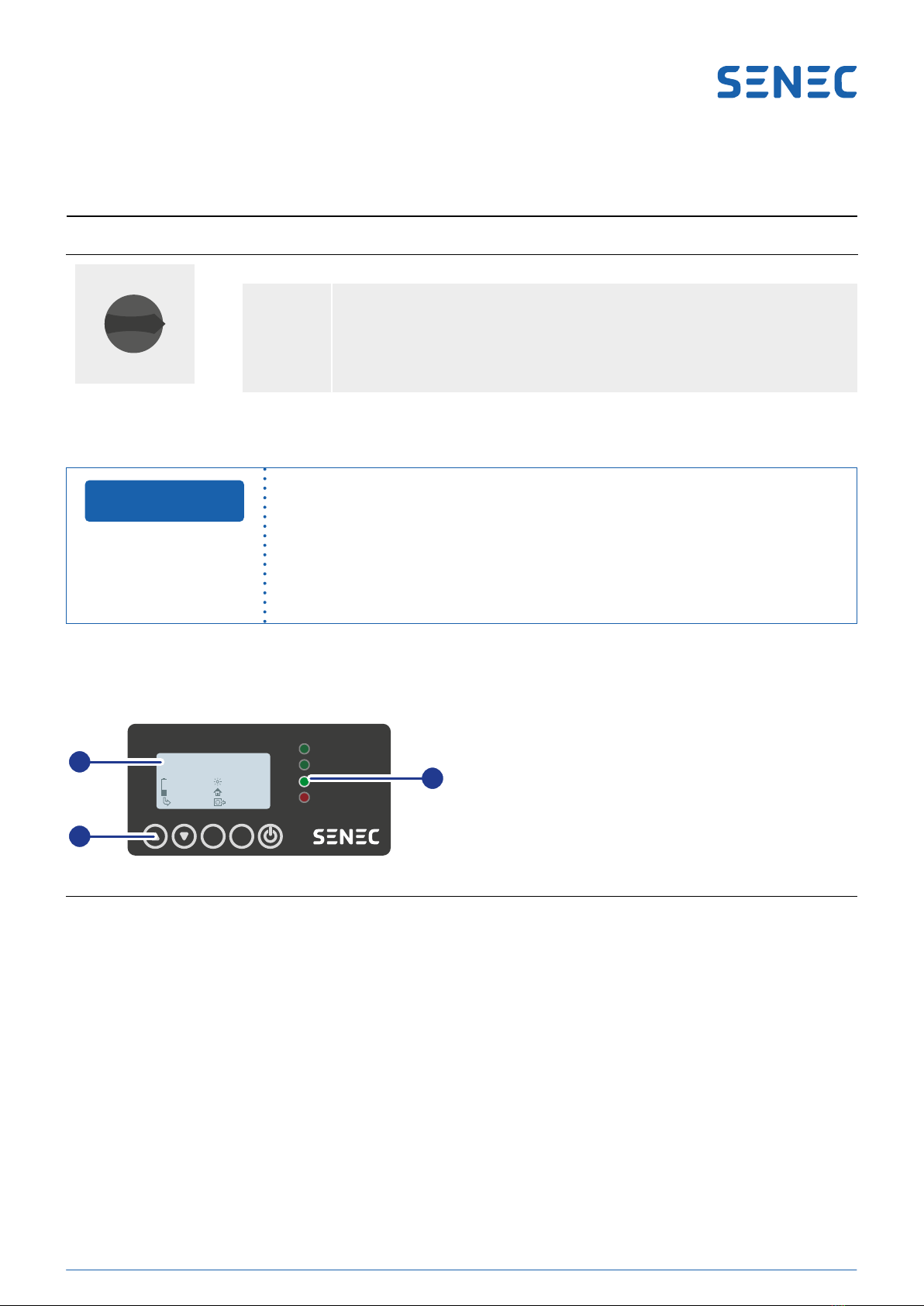
3.2.2 Display
The display is laid out as follows:
OK ESC
Passive
Charge
Discharge
Error
192.168.2.100
Scarica
41.9A
51.6V
2160W
360W
2520W
0W
192.168.2.100
Entladen
41.9A
51.6V
2160W
360W
2520W
0W
2
3
192.168.2.100
Scarica
41.9A
51.6V
2160W
360W
2520W
0W
192.168.2.100
Discharge
41.9A
51.6V
2160W
360W
2520W
0W
1
Fig.4 Display layout
NOTICE
1Display
2Control elements
3LEDs

14
TD140‑090.10 | Version 1.0 | 09/05/2023
The display has the following elements:
192.168.2.100
Discharge
41.9A
51.6V
2160W
360W
2520W
0W
1
2
3
4
5
9
8
7
6
Fig.5 Overview of the display (values shown are examples)
Symbol Meaning
Charge
Discharge
Grid feed-in
Mains draw
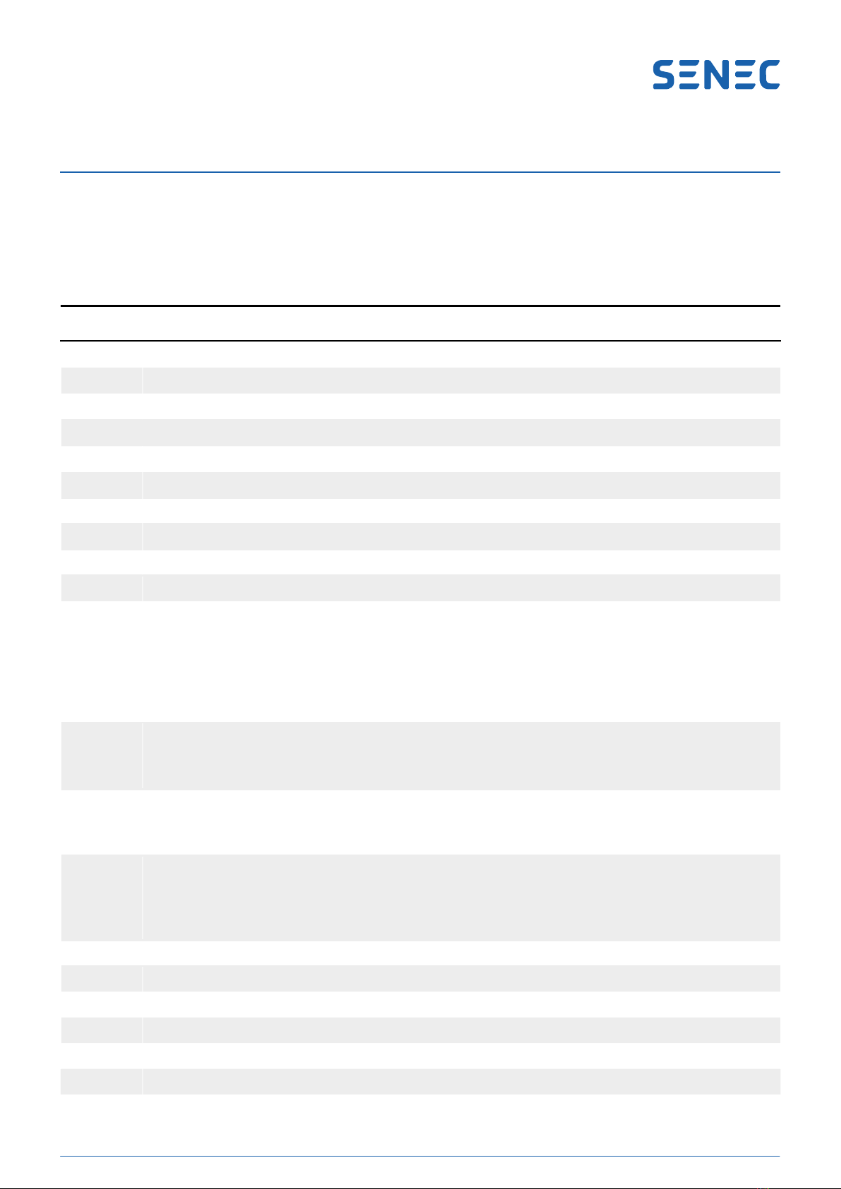
The display has the following LEDs:
LED Designation Explanation
Passive The SENEC battery storage is not being charged or discharged and is in standby mode.
Charge Grid operation is active.
The SENEC battery storage is being charged with excess generated power.
Discharge Grid operation is active.
The SENEC battery storage is discharging the battery modules to provide the necessary power
output.
Error Grid operation is not possible due to a malfunction.
An error message is shown on the display and at my.senec.com.
1IP address
2Status display
3State of charge
4Battery voltage
5Charge or discharge power*
6Charge or discharge current*
7Grid status (mains draw or grid feed‑
in)*
8Power display showing domestic
consumption
9Self‑generated electricity power
display
*For the meaning of the symbols see table
15
TD140‑090.10 | Version 1.0 | 09/05/2023
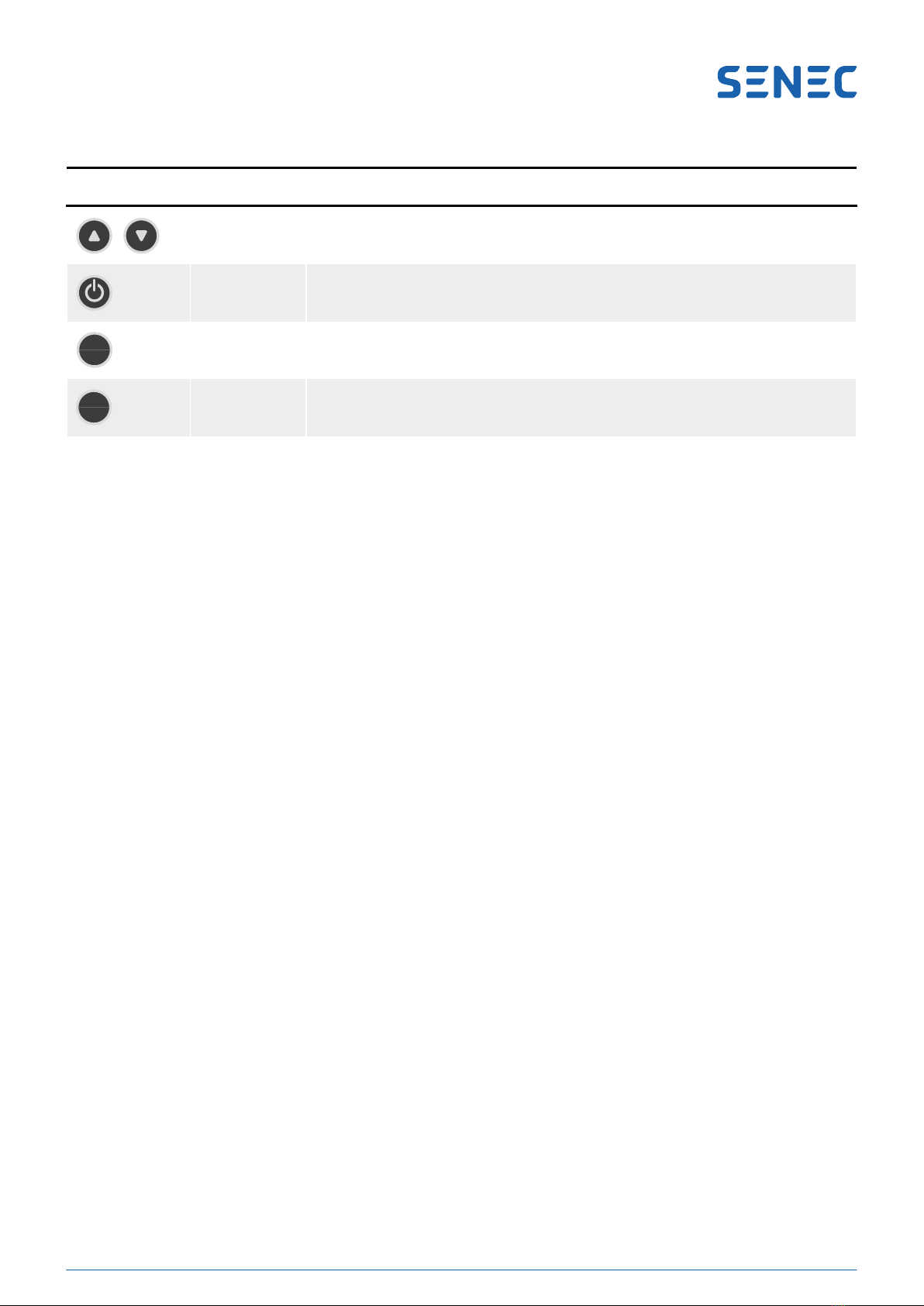
The display has the following control elements:
Control element Designation Function
Navigation Activates the display light
On/off Switches the SENEC battery storage on and off
OK OK Conrms that you wish to switch the battery modules on or off
ESC Escape -
3.3 Description of functions
The SENEC.Home V3 hybrid has a modular setup comprising the following components:
• Case with display
• SENEC.Inverter V3 LV inverter
• Control and charging electronics with communication connections
• Battery modules
The SENEC battery storage can be coupled with other generation installations on the AC and on the DC side. A PV
installation can be connected directly on the DC side. On the AC side, the system can be coupled with additional PV
inverters.
The hybrid function enables the SENEC battery storage either to use the power from the directly connected PV instal‑
lation to charge the battery modules or to feed it into the grid. Surplus energy from other generation units, provided
they supply grid‑compliant alternating current to the domestic power network, can also be stored. When the current
energy generation level does not cover the power demand, the energy stored in the battery modules is fed into the
domestic power network.
The energy output of the generation units is used as follows (in order of priority):
• Direct self‑consumption
• Battery charging
• Public grid feed‑in (except at times when zero feed‑in mode is on)
3.3.1 Case and display
The SENEC battery storage’s case is made of aluminium and houses the battery modules and all other components.
Its adjustable feet allow the SENEC battery storage to be installed in installation locations with slightly uneven sur‑
faces.
Thesidepanel(sidecovers)consistsofameretardantplasticandismagneticallyattachedtothecase.Theside
panelmayonlybeopenedbyaqualiedelectrician.
The display showing status messages and operating statuses is located on the front of the case.

16
TD140‑090.10 | Version 1.0 | 09/05/2023
3.3.2 SENEC.Inverter V3 LV inverter
The SENEC.Inverter V3 LV charges the battery modules primarily from the connected PV generator or using excess
energy generated by other generation units. Alternating current (AC) is converted to direct current (DC) and stored in
the battery modules. The energy required for the household or for covering self‑consumption may come from both
the PV generator and the battery modules.
The SENEC.Inverter V3 LV comprises an actively ventilated metal case and is generally on standby, which means that
self‑consumption is negligible. The SENEC.Inverter V3 LV will activate as soon as the domestic power network is sup‑
plied. Energy can be discharged into the domestic power network (grid operation) once the minimum consumption
reaches 70 W. If consumption drops below this level, the SENEC.Inverter V3 LV will automatically switch to standby
to save energy.
3.3.3 Control and charging electronics
The control unit consists of the main control unit (MCU), the network processor unit (NPU), the isolated power unit
(IPU), circuit breakers, automatic diconnection device and metering units.
The MCU is the main control unit which communicates with and sets parameters for the SENEC.Inverter. The MCU
also controls the battery modules’ internal management system and regulates communication with external devices,
thedisplayanddigitalinputandoutputpoints.TheMCUprovidesthelocalcongurationinterface(webGUI).
The NPU is responsible for communication between the main control unit and the network.
3.3.4 Battery modules
The SENEC battery storage is equipped with the following number of battery modules:
• SENEC.Home V3 hybrid 5: 1x battery module (4.5 kWh useful capacity)
• SENEC.Home V3 hybrid 10: 2x battery modules (9.0 kWh useful capacity)
The battery management system (BMS) integrated into each battery module continuously monitors the safety pa‑
rameters of the module (temperature, current and voltage). The MCU monitors the status of the individual battery
modules. Potential issues such as overtemperature, overcharge or excess charge current are detected and prevented
early on. The BMS is able to shut down charging or discharging in exceptional situations, such as overheating, inde‑
pendently of the MCU.
3.3.5 RCMU (only for product revision 0)
The RCMU (residual current monitoring unit) is located on the IPU and recognises both DC and AC residual current.
This prevents the SENEC battery storage from feeding fault currents into the grid. Otherwise, protection devices such
as RCD switches could be disabled. If a fault current is detected, the SENEC battery storage will be automatically
disconnected from the grid. Starting with product revision 1, the inverter is responsible for fault current recognition.
3.3.6 Overvoltage protection
A type 2 surge protective device (SPD) has been integrated for each PV connection and each MPP as a standard.
Additional protective measures are subject to relevant legal requirements and standards and depend on the existing
installation.

17
TD140‑090.10 | Version 1.0 | 09/05/2023
3.3.7 Selftest
The SENEC battery storage performs a selftest every time it is switched on and after every 24 hours of operation to
diagnose and monitor the available safety devices and the connected PV installation.
The selftest takes 5 to 10 minutes and comprises the following checks:
• Communication test between battery modules
• Calibration of residual current sensor
• DC contactor test
• Test of communication with inverter
• Measurement of insulation resistance
During the selftest, running light LEDs will be shown on the display. The SENEC battery storage must not be switched
off during the selftest. If the selftest cannot be successfully completed, the SENEC battery storage will go into error
mode. Once the selftest has been successfully completed, the SENEC battery storage will switch to normal operation.
For further information on the selftest and possible error messages, please refer to section
“7.4.1Devicenotications“onpage27.
3.3.8 Power meter
A power meter is included to enable full use of the SENEC battery storage’s functionalities. The power meter is in‑
stalled in the switchboard, which means it remains outside of the SENEC battery storage. Depending on the connec‑
tion variant, it may be necessary to install an additional power meter.
The power meter is used to measure the four‑wire three‑phase supply. It measures active power, voltage and fre‑
quency per phase and sends these values to the SENEC battery storage via a data link. To connect to other types of
grid, please get in touch with your SENEC contact.
18
TD140‑090.10 | Version 1.0 | 09/05/2023
4 Scope of delivery
The scope of delivery of the SENEC battery storage comprises 3 packaging units:
• SENEC battery storage
• Accessories kit (included with SENEC battery storage)
• Battery modules (individually packaged)
Number Designation
SENEC battery storage
1SENEC.Home V3 hybrid
5Cover
Accessories kit
1Power meter 1
1Patch cable (Cat 6, 1 m, red)
1Patch cable (Cat 6, 1 m, blue)
2Battery terminal cable (for battery module B with SENEC.Home V3 hybrid 10)
1Modular adapter (Cat 6 STP)
6Cable tie
12 Cylinder head screw (hexagon socket, M6 x 10)
• 4x for connecting the battery terminal cables to the battery module
• 2x for connecting the battery terminal cables to the busbars
• 2x for connecting the bracket to the storage case
• 2x for connecting the angle bracket of the tilt protection
• 2x spares
6Cylinder head screw (hexagon socket, M5 x 10)
• 4x for connecting the brackets to the battery modules
• 2x spares
6Button-head screw (hexagon socket, M4 x 8)
• 4x for top cover
• 2x spares
8 Lock washer (M6)
• 4x for the battery terminals
• 2x for connecting the battery terminal cables to the busbars
• 2x spares
3Jumper (2.54 mm)
1Suction pad (55 mm)
2Battery module bracket
1TD110-101 Battery module sticker A
1TD110-102 Battery module sticker B
1Safety information insert for end clients

19
TD140‑090.10 | Version 1.0 | 09/05/2023
Number Designation
1Angle bracket for tilt protection
1Flat belt for tilt protection (30 mm x 100 mm, black)
2Cage nut for tilt protection (M6)
Battery modules
1 – 2 Battery modules
• SENEC.Home V3 hybrid 5: 1x battery module (4.5 kWh useful capacity)
• SENEC.Home V3 hybrid 10: 2x battery modules (9.0 kWh useful capacity)

20
TD140‑090.10 | Version 1.0 | 09/05/2023
5 Storage
When storing a non‑installed SENEC battery storage, note the permissible storage temperature of ‑20 °C – +50 °C,
at a relative humidity of 45 % – 85 %.
Non‑installed battery modules may only be stored by your installer.
Long storage periods may lead to irreparable damage!
The battery modules must be installed and charged by your installer immediately subsequent
to delivery in order to avoid deep discharge and thus irreparable damage to the battery mod‑
ules.
Ê New battery modules that are to be stored for a long time must be charged to at least
30 % if the production date was 5 months prior or earlier.
Ê Battery modules that have already been put into operation must be recharged to at least
30 % every 5 months.
Ê They may only be charged with a SENEC.Home V3 hybrid storage; other charging devices
may not be used.
Ê The charging date for each battery module must be documented.
The packaging of the battery modules contains a label with the date of manufacture. On the basis of the production
date, your installer will recognise whether a battery module must be charged or not.
NOTICE
Table of contents
Popular Inverter manuals by other brands


AIMS Power
AIMS Power GEN2000W120V manual

Avlite
Avlite AV-SIGN-20 Installation & service manual

LSIS
LSIS LSLV0055H100-4COFN manual

Solax
Solax X1 Series Quick installation guide

Mitsubishi Electric
Mitsubishi Electric PV-PNS04ATL-IT Operation manual

Turbo Energy
Turbo Energy HYBRID 48V 5.0 Series instruction manual