Seneca Z-MODEM-3G User manual

MI003781-E.DOCX ENGLISH 1/8
INSTALLATION
MANUAL
Manual language English
Series Z-PC
Product
Z
-
MODEM
-
3G
Description 2G and 3G modem, GSM850, EGSM900, DCS1800,
PCS1900, WCDMA900 and 2100 Frequency
Contents
1. PRELIMINARY WARNINGS 2
2. PRELIMINARY USE INSTRUCTIONS 2
3. GENERAL SPECIFICATIONS 2
4. TECHNICAL SPECIFICTIONS 3
Power Supply 3
Modem 3
SIM 3
USB 3
Antennas 3
Environmental Conditions 4
Case 4
Standards 4
Insulations 4
5. INSTALLATION RULES 5
6. ELECTRICAL CONNECTIONS 5
Power Supply 6
Micro USB 6
Antennas 7
7. LED INDICATIONS ON THE FRONTAL PANEL 7
LED meaning 7
8. PURCHASE ORDER CODE 7
9. MODULE LAYOUT 8
10. DECOMMISSIONING AND DISPOSAL 8
Manufacturer
Seneca srl
Registered office: Via Austria 26
35127 – Z.I. - Padua – I
Tel +39.049.8705355- 8705355
Fax +39 049.8706287
WEB www.seneca.it
Mail Technical support: supporto@seneca.it
Product information: commerciale@seneca.it
This document is the property of SENECA srl. Unauthorized duplication and reproduction
is strictly forbidden. The content of this document corresponds to the described products
and technologies. Stated data may be modified or supplemented for technical and/or
sales purposes.
Programming tools, manuals, templates, examples, etc. for the product can be
downloaded free of charge from www.seneca.it/products/z-modem-3g.

MI003781-E.DOCX ENGLISH 2/8
1.
PRELIMINARY
WARNINGS
The full content of this manual must be read before performing any
operation. The module must only be used by qualified electricians. Specific
documentation is available from www.seneca.it/products/z-modem-3g
The module must be repaired and damaged parts replaced by the
Manufacturer. The product is sensitive to electrostatic discharges. Take
appropriate measures during any operation.
The warranty is null and void in the event the module or devices supplied by
the Manufacturer, necessary for its correct operation, are improperly used
or tampered with and, in any case, if the instructions contained in this
manual were not followed.
2.
PRELIMINARY
USE
INSTRUCTIONS
Don’t obstruct ventilation slots with any objects.
Don’t place the module next to devices that generate heat.
3.
GENERAL
SPECIFICATIONS
- Modem with HSDPA/UMTS/EDGE/GPRS protocol.
It can be connected to a wireless network with a SIM, that is without subscribing with
a physical provider using a cable connection such as a telephone network, ADSL, etc.
- 2 SMA connectors for the two antennas: MAIN and DIVERSITY.
For better performance we recommend to positioning the antennas at a 90° angle
between each other.
- The antenna supplied can be replaced with one with a higher gain.
- Removable terminals with section of 2.5 mm2.
- 5 frequency bands.
- Slot for push-push mini SIM.
- Micro USB 2.0 interface connector to exchange data with Z-TWS4 and Z-PASS1.
- The product can be installed on an IEC EN 60715 omega guide.
- LED front indications: Supply (PWR) and status (STAT).
1

MI003781-E.DOCX ENGLISH 3/8
4.
TECHNICAL
SPECIFICTIONS
Power Supply
Power supply 11 −40 Vor 19 −28 V50/60Hz
Absorption 4.5 W max
Connections 0.2 – 2.5 mm
2
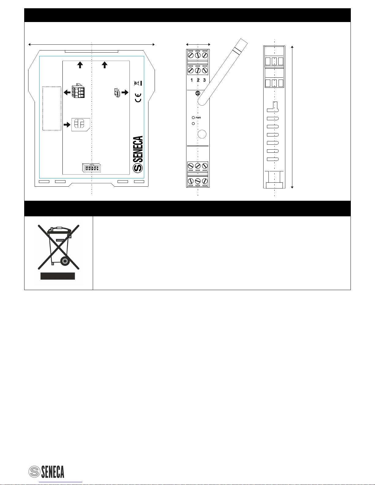
screw removable terminals (AWG 24-12)
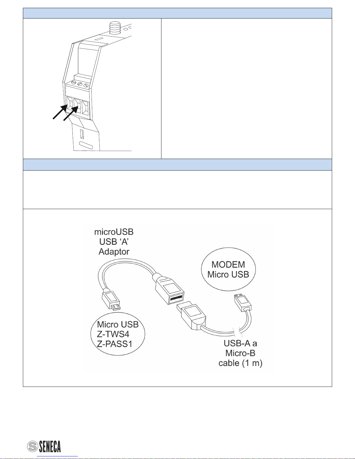
Modem
Frequencies GSM / GPRS / EDGE
Quad-band: GSM850 GSM 900, DCS 1800, PCS 1900
UMTS / HSPA+
Dual-Band: WCDMA2100/900 2100/850, 1900/850
Transmitted power GSM/GPRS:
Class 4 (2W): GSM850, EGSM900
Class 1 (1W): DCS1800, PCS1900
EDGE:
Class E2 (0.5W): GSM850, EGSM900
Class E1 (0.4W): DCS1800, PCS1900
UMTS:
Class 3 (0.25W): WCDMA2100/900, 2100/850,1900/850
Connection speed GPRS Class B, multi-slot class 12,
Decoding: CS1-4,
Max download speed: 85.6kbps,
Max upload speed: 85.6kbps,
EDGE multi-slot class 12,
Decoding: MSC1-9,
Max download speed: 236.8kbps;
Max upload speed: 236.8kbps
UMTS R99 speed: 384 kbps Download/Upload
SIM5350L series: HSDPA category 10 - 14.4 Mbps+ HSUPA
category 6 - 5.76 Mbps
DRX Diversity receiver SIM
SIM type Mini SIM @ 3V
Introduction and removal Facilitated by the Push-push system
USB
Type Micro USB
Use Data transfer for Z-TWS4 and Z-PASS1
Antennas
"Main" antenna (mandatory) SMA female, 50 Ωimpedance
"Diversity" antenna (recommended)
SMA female, 50 Ωimpedance
2

MI003781-E.DOCX ENGLISH 4/8
Environmental Conditions
Protection rating IP20
Operating temperature -20 −+60 °C
Storage temperature -40 −+85 °C
Humidity 10 – 90% non condensing
Altitude up to 2000 m above sea level
Case
Weight 47g
Dimensions 41 x 44 x 26 mm (terminal excluded)
Case PA6, black
Standards
EN 301 511 Global System for Mobile communications (GSM);
Harmonized EN for mobile stations in the GSM 900
and GSM 1800 bands, article 3.2 of the R&TTE
Directive (1995/5/EC).
EN 301 489-1 Common technical requirements
EN 301 489-1 Specific conditions for mobile and portable radio
and ancillary equipment of digital cellular radio
telecommunications systems (GSM and DCS)
EN61000-6-4 Emission, industrial environment
EN64000-6-2 Immunity, industrial environment
EN60950 Safety
Insulations
1500 Vinsulation between modem and power supply
3

MI003781-E.DOCX ENGLISH 5/8
4
5.
INSTALLATION
RULES
The module has been designed for vertical installation on an IEC EN 60715 omega guide. For optimal
operation and long working life, adequate ventilation must be provided. Avoid positioning cable ducts or
other objects so that they obstruct the ventilation slots. Avoid mounting modules over equipment
generating heat. Installation in the bottom part of the distribution board is recommended
OMEGA IEC EN 60715 guide installation on and removal from.
Insertion on the IEC EN 60715 guide:
1) Move the four hooks on the back of the module
outwards as illustrated in fig. 1b.
2) Insert the module aligning the IDC10 rear connector
to the female of the Seneca support for the IEC EN
60715 guide.
3) To secure the module to the guide, tighten the four
hooks on the side of the IDC10 rear connector as shown
in fig. 1a.
Removal from the IEC EN 60715 guide:
As illustrated in figure 1b:
1) Move outwards the four hooks on the side
of the module, using a screwdriver.
2) Extract the module from the guide.
6.
ELECTRICAL
CONNECTIONS
IDC10 rear connector (POWER AND PORT 1)
In the figure you can see the meaning of the IDC10
connector pins if you want to provide signals
through them.
Module power is available from the rear connector
or via terminals 2 and 3.
Potential Z-PC-DINAL2-17.5 use
If the Z-PC-DINAL1-17.5 accessory is used the
power supply
and communication signals may be provided by the
terminals block.
The illustration shows the meaning of the various
terminals and DIP-switch position, found in all
Seneca supports for the IEC EN 60715 guide (not
used for the Modbus network).
GNDSHLD: Connection cable signal protection
shield (recommended).

MI003781-E.DOCX ENGLISH 6/8
Power Supply
3
21
The power supply must be connected to the
IDC10 bus or to terminals 2 and 3.
The supply voltage must be between 10 and
40V(any polarity), or between 19 and 28 V.
The upper limits must not be exceeded in
order to avoid serious damage to the
module.
The power supply source must be protected
from any malfunctions using appropriately-sized
safety fuses.
Micro USB
The module has a microUSB connector, you can connect the Z-MODEM-3G to Z-TWS4
or to Z-PASS1 through it. The adaptor cables, supplied with the module, must be
connected as shown in the figure.
For further information, refer to the Z-TWS4 or Z-PASS1 user manuals.
5

MI003781-E.DOCX ENGLISH 7/8
Antennas
Z-MODEM-3G
STAT
USB
One antenna (ANTENNA-STILO-EA247) is
supplied with Z-MODEM-3G.
This antenna must be screwed into the SMA
MAIN connector.
An second "diversity" antenna can be
connected to the module in order to improve
the performance of the modem.
For more performance you can use an antenna
with a better gain (see accessories).
Warning: The modem don’t work properly if
only the "div" (diversity) antenna is connected.
7.
LED
INDICATIONS
ON
THE
FRONTAL
PANEL
LED meaning
LED STATUS LED meaning
PWR Green ON The module is switched ON
PWR Green OFF The module is switched OFF
STAT yellow Flashing Connected to the network
STAT yellow Fast flashing PPP connection established
STAT yellow ON Network search
8.
PURCHASE
ORDER
CODE
ANTENNA-STILO-EA247 SMA connector, 90° (like the one supplied)
A-GSM 3m cable, with sheathed adhesive antenna
ANT-LINK1-MG 3m cable, with magnetic-base antenna
CAVO-USBA-MICROB-MP 1m cable, from male A-type to male microB-type
6

MI003781-E.DOCX ENGLISH 8/8
9.
MODULE
LAYOUT
111210
8 97
111,0 mm
17.5 mm100 mm
MicroUSBOTG
fordatainput
fromZ-TWS4 orZ-PASS1
ET004892B
Z-MODEM-3G
3G Modem for
Z-TWS4 /Z-PASS1
MADEIN ITALY
DIVERSITY
Antenna
MAIN
Antenna
PowerSupply 2,3
11-40Vdc
19-28Vac(50-60Hz)
Max3W
Connector
Rearbus
SIMCard
Push-Push
connector
+
Z-MODEM-3G
STAT
USB
DIV
MAIN
10.
DECOMMISSIONING
AND
DISPOSAL
Electrical and electronic waste disposal (applicable in the European Union and
other countries with recycling). The symbol on the product or packaging indicates
that the product cannot be discarded as domestic waste. It should be taken to an
authorised recycling centre for electrical and electronic waste. Ensuring that the
product is suitably discarded will avoid potential negative impacts on the
environment and human health, that could be caused by non compliant product
disposal. Material recycling will contribute to the preservation of natural resources.
To receive further information, please contact your local waste disposal service
centre or product dealer.
7
Table of contents
Other Seneca Modem manuals