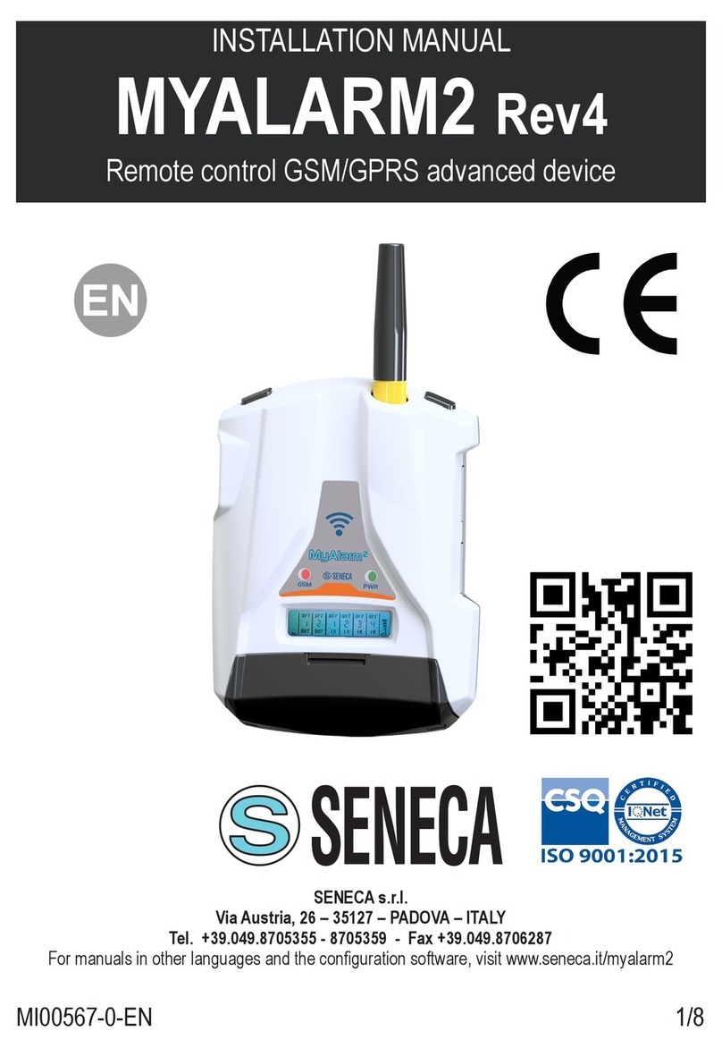
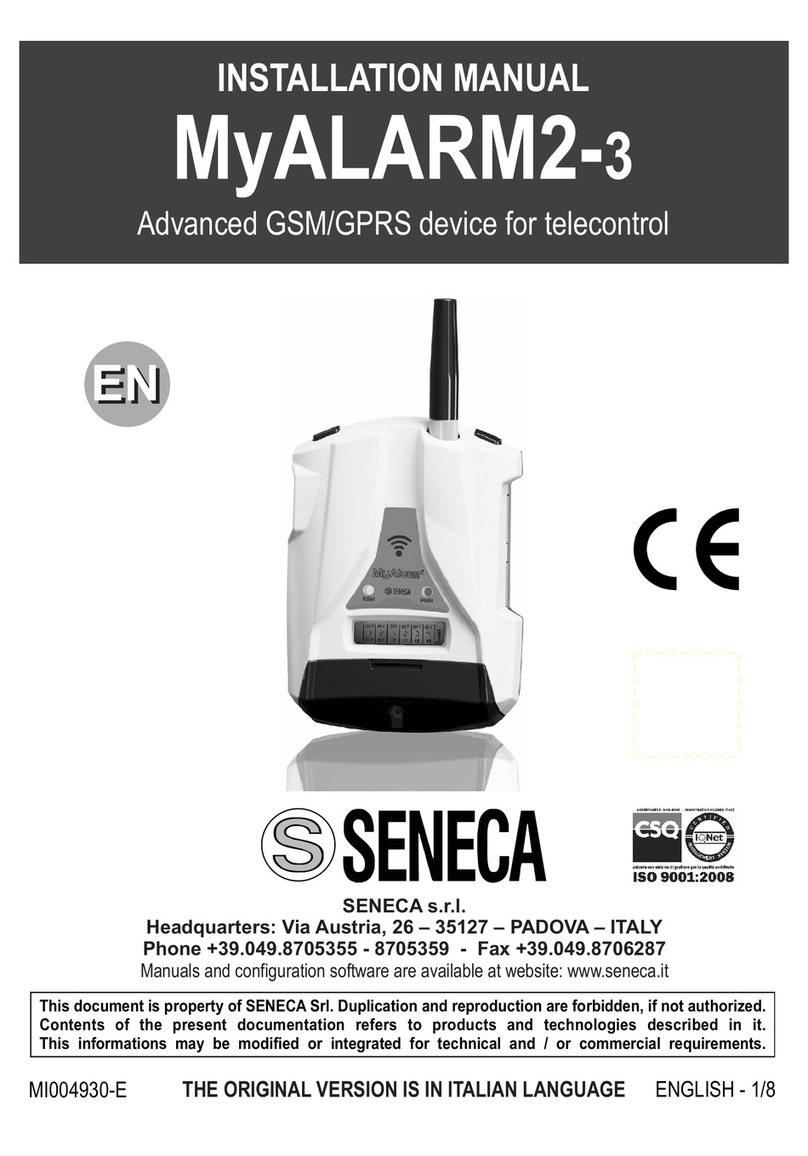
Seneca MyAlarm3 Cloud User manual

QUICK START
MyAlarm3 Cloud
GSM/GPRS device for remote alarm and control
SENECA s.r.l.
Via Austria, 26 – 35127 – PADOVA – ITALY
Tel. +39.049.8705355 - 8705359 - Fax +39.049.8706287
For manuals in other languages, visit www.seneca.it/myalarm3-cloud
EN
MI00553-2-EN 1/4
“MyAlarm3 Cloud”
APP
This document is the property of SENECA srl. Copies and reproduction are prohibited unless authorised.
The content of this document corresponds to the described products and technologies.
Stated data may be modied or supplemented for technical and/or sales purposes.
DOCUMENTATION

SAFETY REGULATIONS
The warranty shall become null and void in the event of improper use or tampering with the device or accessories
supplied by the manufacturer as necessary for its correct operation, and if the instructions contained in this manual
are not followed.
Electrical and electronic waste disposal (applicable in the European Union and other countries with recycling).
The symbol on the product or its packaging shows the product must be surrendered to a collection centre
authorized to recycle electrical and electronic waste.
The module must be repaired and damaged parts replaced by the Manufacturer. The product is sensitive to
electrostatic discharges. Take appropriate measures during any operation.
SIGNALS VIA LED ON FRONT PANEL
2/4
The full content of this manual must be read before any operation.
The device is to be exclusively used by qualied electricians.
• Do not apply different voltages or higher voltages than indicated between terminals, or between any terminal and earth (voltages
greater than 50Vdc)
• Do not use the MyAlarm3 Cloud control unit if damaged, or if signs of possible damage are visible on it.
• Do not remove the internal battery.
• Do not use the MyAlarm3 Cloud control unit if it runs abnormally.
• Do not touch the control unit terminals during use
• For a correct use, use the cables supplied.
• Make sure the internal battery is charged if you intend to use the MyAlarm3 Cloud control unit without power.
• Use the MyAlarm3 Cloud control unit as described in the manual downloadable at www.seneca.it/myalarm3-cloud.
• Before each use, refer to the electrical connections shown in the manual.
MODULE LAYOUT
80 mm
108 mm
32 mm
8 mm
CASE DIMENSIONS SYMBOLS ON THE ENCLOSURE
ON / OFF power button
GPS antenna
Menu access button
Slot for mini SIM
Slot for micro SD card
Micro USB connector
Weight 150 g Case Polycarbonate / ABS material
GPS
SIM
SD
LED STATUS LED MEANING
GSM
(YELLOW)
Off MyAlarm3 Cloud OFF
Fast ashing
(64 ms ON / 300 ms OFF)
Network search
No signal
SIM card with incorrect pin
Slow ashing
(64 ms ON / 3000 ms OFF)
GSM network registration successful, but internet connection not
active
Medium ashing
(64ms ON/ 800 ms OFF)
Successful access to the Internet
correct APN
Registration to the GPRS network successful
PWR
(GREEN)
On MyAlarm3 Cloud ON
Off MyAlarm3 Cloud OFF
WARNING
CAUTION

TECHNICAL SPECIFICATIONS
3/4
STANDARDS
ETSI EN 301-489-7
EN 301 511
EN 301 489-1
IEC / EN 60950
Power supply
Voltage
Absorption
Internal batteries
6 - 15 Vdc; 500 mA Max
3.5 W Max
Lithium Ion 3.7 V, 1100 mAh, rechargeable, non-replaceable
Voltage
output
+12 Vdc 50 mA (maximum current)
Temperature
sensor
NTC internal (as standard), external (option*) thermistor
Ambient
conditions
Temperature
Humidity
Storage
temperature
Protection
rating
Seneca recommends use at 0 to 45°C for correct operation
With the power supply present: -20 ÷55°C.
With use of the battery (when discharged): -20 ÷5°C Charging is possible in the range: 0 ÷45°C.
30%– 90% non condensing.
From
-20°C to 20°C < 1 year; from -20°C to 45°C < 3 months; from -20°C to 60°C < 1 month
IP40
Connections
Spring clamps, 3.5 mm pitch, connector for Micro USB and SMA connector for GSM, MMCX
for GPS antennas (option*)
Internal memories
FLASH 1 MB + 8 MB
Slot Type/
Memory Micro SD
Push-Push for SD card and SD HC card / max 32GB
Slot Type SIM
Push-Push for mini SIM (15 x 25 mm)
Digital inputs
Type
Maximum
frequency
Threshold OFF
Threshold ON
4 inputs Reed, contact, PNP, Pulscap
30 Hz
0 ÷3 Vdc, I > 1 mA
6 ÷24 Vdc, I > 3 mA
Analogue
inputs 2 inputs, Voltage 0 ÷30 Vdc / Current 0 ÷20 mA, 0.1% of full scale
Display 128x32 LCD Dots with visible area of 39 mm x 8.6 mm
USB
1 micro USB for conguration and supply
CPU 120 MHz 32 bit ARM
GSM QUAD BAND (850 / 900 / 1800 / 1900 MHz)
Digital outputs 2 outlets Relay 3 A max - 250 V SPST (with shared terminal)
GPS SPECIFICATIONS (if present in the purchased model)
RECEIVER 22 channels
SENSITIVITY -165 dBm
FIX TIME 32 s usually
ACCURACY Up to 2.5 m
* To view all accessories visit www.seneca.it/products/myalarm3-cloud.

4/4
CONTACT INFORMATION
CAUTION: to use this product it is necessary to use the dedicated "MyAlarm3 Cloud" APP downloadable via the QR Code
on the cover or via the app store and apple store.
First startup procedure:
1. Download the iOS / Android APP (see QR Code on the cover or search for MyAlarm3 Cloud in the stores);
2. Download the installation manual from the APP or from the QR Code on the cover to get the complete guide;
3. Insert the mini SIM card into the switched-off MyAlarm3 Cloud (*);
4. Check that the SD card is correctly inserted (see image 1);
5. Power the control unit by connecting it to the Power Supply socket or alternatively use the cable with the forks (do not turn on the
device without power as it is in shipping mode).
To conrm the rst startup procedure is correct, the Yellow GSM LED will change ashing from 1 to 3 times a second.
(*) if a SIM card other than the one supplied with the KIT is used, ensure you have removed the locking PIN when you switched on
using another device (i.e. a smartphone)
Simplied activation procedure (for the complete procedure see the installation manual):
1. Open the MyAlarm3 Cloud APP, register your Seneca cloud account (if you don't already have one) and wait for the account
activation email;
2. After receiving the account activation email, select the "ACTIVATE ACCOUNT" key.
3. After activating the account, open the app again and log in for the rst time entering the username and password you hasve just
created;
4. Enter the 5 + 10 character "activation code" on the back of the control unit and select the "ACTIVATE" button (if it is not the rst
service associated with the account, from the app click "change system "and then select the
“ADD” button); (*)
5. From now on, the service is active and the control unit's owner account can access the MyAlarm3 Cloud system from both the web
browser and the MyAlarm3 Cloud mobile app, as well as invite other users to use his newly activated MyAlarm3 Cloud.
Switching on and menu keys:
MyAlarm3 Cloud is tted with an ON/OFF PWR key positioned in the LH top corner (Figure 2).
To switch it off, keep the PWR key pressed for a few seconds. The device is tted with a MENU key, in the RH top corner.
Pressing this key displays the parameters.
N.B.: in order to guarantee the correct operation of the MyAlarm3 Cloud control unit, THE CONTENT OF THE SD CARD MUST NOT
BE REMOVED
IMPORTANT! SENECA s.r.l. is not responsible for the length of time, operation or lack of notications (alarms, information
data, etc...) provided through push notications, SMS, email, voice calls, etc. These communications depend on third parties
internet connectivity and/or telephony services on which SENECA s.r.l. can not intervene directly. For any further information
please see the Cloud services supply contract. Thank you.
CONTROL UNIT INSTALLATION AND FIRST ACTIVATION
Figure 2Figure 1
AUX 1
Common to the two relays
AUX 2
DIN 1
DIN 2
DIN 3
DIN 4
AUX+12 Vdc
GND
AIN 1
AIN 2
GND
NTC
Supply
Supply
Input for sensor
ELECTRICAL CONNECTIONS
Other manuals for MyAlarm3 Cloud
1
Table of contents
Other Seneca Security System manuals
Popular Security System manuals by other brands

Power Max
Power Max DE5450 installation instructions

Blaupunkt
Blaupunkt Q3000 installation guide

Commax
Commax DR-nKM user manual

Honeywell
Honeywell ADEMCO VISTA-40 Programming guide

Se-Kure Controls
Se-Kure Controls Klothing Kontrols SK-3600 Series installation instructions

DSC
DSC PC1000 installation manual