manuals.online logo
Brands
  1. Home
  2. •
  3. Brands
  4. •
  5. Se-Kure Controls
  6. •
  7. Security System
  8. •
  9. Se-Kure Controls Klothing Kontrols SK-3600 Series User manual

Se-Kure Controls Klothing Kontrols SK-3600 Series User manual

Other Se-Kure Controls Security System manuals

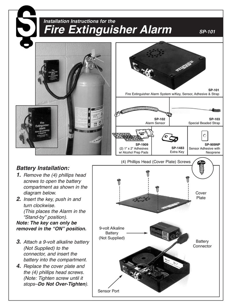
Se-Kure Controls SP-101 User manual

Se-Kure Controls

Se-Kure Controls SP-101 User manual

Se-Kure Controls Mini T Series User manual

Se-Kure Controls

Se-Kure Controls Mini T Series User manual

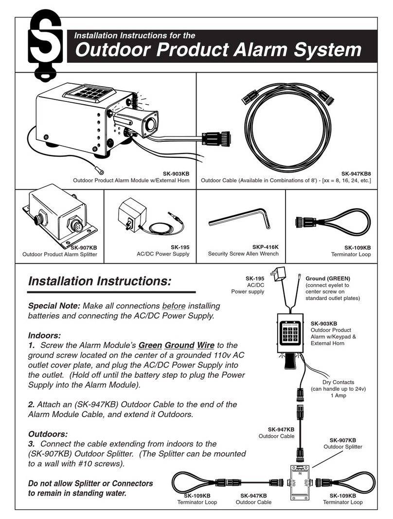
Se-Kure Controls SK-903KB User manual

Se-Kure Controls

Se-Kure Controls SK-903KB User manual

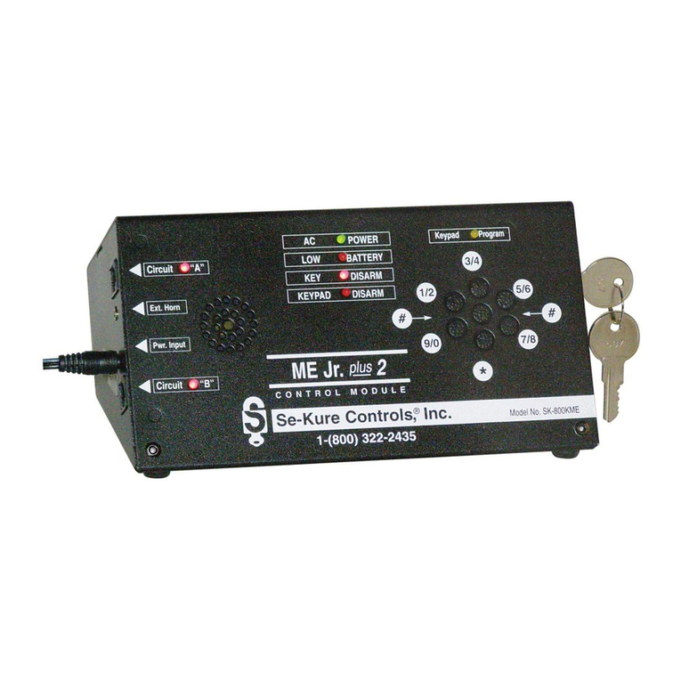
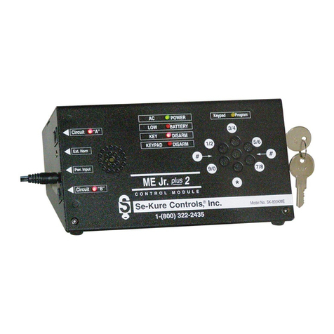
Se-Kure Controls ME Jr. plus 2 SK-800MEI Series User manual

Se-Kure Controls

Se-Kure Controls ME Jr. plus 2 SK-800MEI Series User manual

Se-Kure Controls MicroMini SK-4841 User manual

Se-Kure Controls

Se-Kure Controls MicroMini SK-4841 User manual

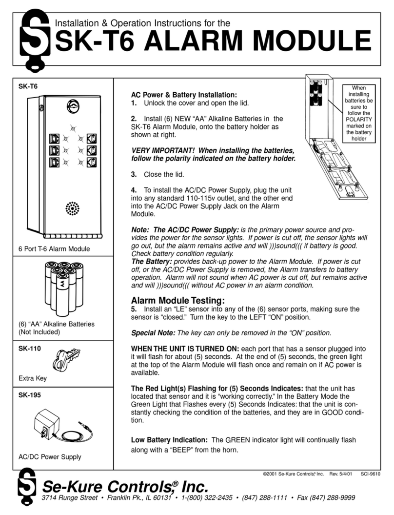
Se-Kure Controls SK-T6 Installation instructions

Se-Kure Controls

Se-Kure Controls SK-T6 Installation instructions

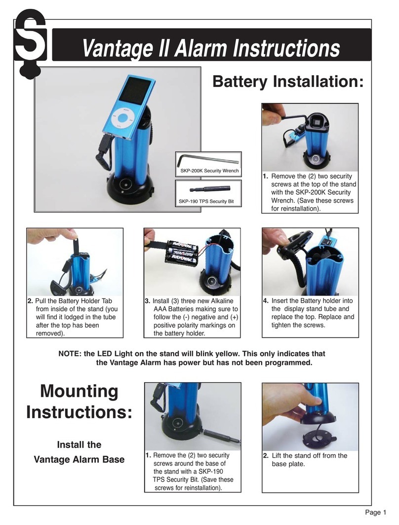
Se-Kure Controls Vantage II User manual

Se-Kure Controls

Se-Kure Controls Vantage II User manual

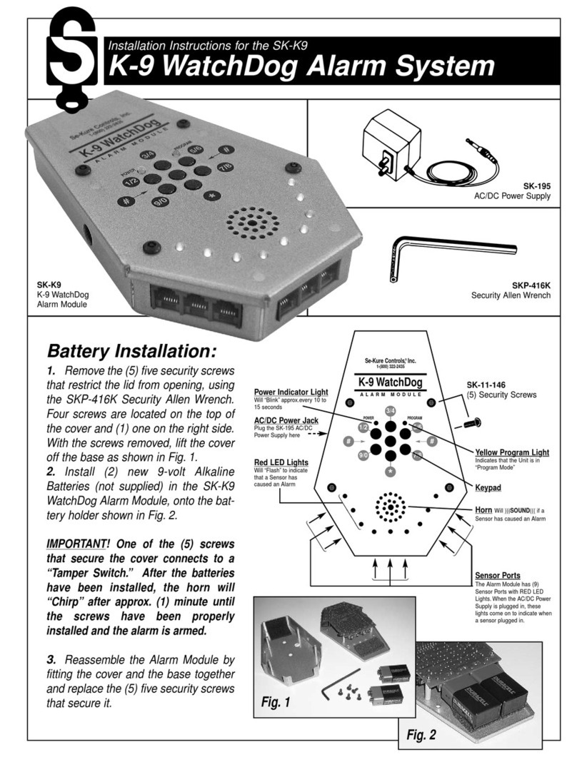
Se-Kure Controls K-9 WatchDog User manual

Se-Kure Controls

Se-Kure Controls K-9 WatchDog User manual

Se-Kure Controls SK-800KME Series User manual

Se-Kure Controls

Se-Kure Controls SK-800KME Series User manual

Se-Kure Controls SK-554NP-RKAC-4 User manual

Se-Kure Controls

Se-Kure Controls SK-554NP-RKAC-4 User manual

Se-Kure Controls SK-554 User manual

Se-Kure Controls

Se-Kure Controls SK-554 User manual

Se-Kure Controls LE PLUS User manual

Se-Kure Controls

Se-Kure Controls LE PLUS User manual

Popular Security System manuals by other brands

Polon-Alfa 4000 Installation and maintenance manual

Polon-Alfa

Polon-Alfa 4000 Installation and maintenance manual

Nexcom NViS 14162 Series user manual

Nexcom

Nexcom NViS 14162 Series user manual

Eminent EM8670 Quick install

Eminent

Eminent EM8670 Quick install

urmet domus alpha 1060 INSTALLATION AND USE BOOKLET

urmet domus

urmet domus alpha 1060 INSTALLATION AND USE BOOKLET

SmartPool YardGuard YG03 manual

SmartPool

SmartPool YardGuard YG03 manual

DSC PC5964 Mounting instructions

DSC

DSC PC5964 Mounting instructions

Secure USAB-1 operating instructions

Secure

Secure USAB-1 operating instructions

B&B 480 SERIES Operation & maintenance manual

B&B

B&B 480 SERIES Operation & maintenance manual

ADEMCO VISTA-20P Series Installation and setup guide

ADEMCO

ADEMCO VISTA-20P Series Installation and setup guide

Inner Range Concept 2000 user manual

Inner Range

Inner Range Concept 2000 user manual

Johnson Controls PENN Connected PC10 Install and Commissioning Guide

Johnson Controls

Johnson Controls PENN Connected PC10 Install and Commissioning Guide

Aeotec Siren Gen5 quick start guide

Aeotec

Aeotec Siren Gen5 quick start guide

Swann SW-P-MC2 Specifications

Swann

Swann SW-P-MC2 Specifications

Ecolink Siren+Chime user manual

Ecolink

Ecolink Siren+Chime user manual

EDM Solution 6+6 Wireless-AE installation manual

EDM

EDM Solution 6+6 Wireless-AE installation manual

Siren LED GSM operating manual

Siren

Siren LED GSM operating manual

Detection Systems 7090i Installation and programming manual

Detection Systems

Detection Systems 7090i Installation and programming manual

FRIEDLAND MA10 Installation and operating instructions

FRIEDLAND

FRIEDLAND MA10 Installation and operating instructions

manuals.online logo
manuals.online logoBrands
  • About & Mission
  • Contact us
  • Privacy Policy
  • Terms and Conditions

Copyright 2025 Manuals.Online. All Rights Reserved.

Installation Instructions for the
Klothing Kontrols Alarm SK-3600 Series
SK-3600
Klothing Kontrol
Alarm Module SK-3660S
5' (Coiled) plus 8' (Straight) Klothing Kontrol Cable with Lasso
SK-3653S
12' (Coiled) Klothing Kontrol Sensor for Garment Sleeves
SK-3652S
12' (Straight) Standard Klothing Kontrol Cable with Lasso
SK-3617
12' (Coiled) Klothing Kontrol Sensor
SK-3699
(Optional) “Flashing Light” for top of display SKP-416K
Security Allen Wrench
SK-11-AA
(included)
(6) “AA” Alkaline
Batteries
SK-336
Universal Saddle
Bracket
(optional)
U-Bolt & Nuts
Included with Alarm
Module
Battery & U-Bolt Installation:
1. Remove the two security screws that restrict the lid from opening, using
the SKP-416K Security Allen Wrench. These screws are located at the bot-
tom of the cover on each side. With the screws removed, open the cover.
2. Install six (6) new “AA” Alkaline Batteries, supplied with the SK-3600
Klothing Kontrol Alarm Module, onto the battery holder shown in Fig. 1.
VERY IMPORTANT! When installing batteries, always
follow the polarity indicated on the battery holder.
3
.While the unit is still open, install the Alarm Module to the display with
the U-Bolt & Nuts as shown in Fig. 2.
4. Close the lid and replace the (2) two security screws to secure cover.
5. Please note that theAlarm Module has a tamper switch, and you
cannot arm the unit until the security screws have been replaced.
Fig. 1 Fig. 2
Alarm Module Testing:
6. Install at least one sensor into any of the (20) twenty sensor ports making sure the sensor(s) are closed on a garment,
and arm the unit using the keypad instructions.
When the unit is Armed: Each port that has a sensor plugged into it will flash for about (2) seconds. At the end of five sec-
onds, the green light at the top of the Alarm Module will flash once every fifteen (15) seconds.
The Red Light(s) Flashing for (5) Seconds Indicates: That the unit has located that sensor and it is “Working Correctly.”
The Green Light that Flashes Every (15) Seconds Indicates: That the unit is constantly checking the condition of the bat-
teries, and they are in GOOD Condition.
Low Battery Indication: The GREEN indicator light will continually flash and “Beep”, (approximately ever 10 seconds).
When installing
“AA” Batteries
be sure to
follow the
polarity marked
on the battery
holder.
Also available:
the SK-336
Universal
Saddle Bracket
Lights:
Green LED Light– “Flashes”
Every 10 Seconds to Indicate
Unit Is Operating
Red LED Lights– “Flash”
To Indicates which Sensor
Caused an Alarm
Yellow LED Light– Indicates
That The Unit Is In “Program
Mode”
Note: The Cover Screws
Must Be Installed For
Alarm To Operate.
(Remove these (2) screws
to install batteries. Close
cover and replace screws).
Se-Kure Controls,®Inc.
3714 Runge Street • Franklin Park, IL 60131 • 1-(800) 322-2435 • (847) 288-1111 • Fax: (847) 288-9999
Rev. 6/23/99 SCI-9642©1999 Se-Kure Controls,®Inc.
Operating Instructions:
1. Dis-Arm the Klothing Kontrol Alarm Module by entering
the Current Access Code on the keypad.
2. Connect a sensor to the merchandise that is to be pro-
tected, then plug it into one of the (20) twenty sensor ports,
(10 on each side of the Klothing Kontrol Alarm Module).
Continue plugging sensors into the Alarm Module after they
have been attached to merchandise. You may use all the
available sensor ports.
3. Activate the alarm by entering the Access Code. The
Klothing Kontrol Alarm Module will now independently scan
the twenty sensor ports for tampering. The unit also con-
tinually checks the battery condition with a GREEN flash-
ing light to show it is operating.
Tampering is the removal of Sensors from the Alarm
Module, from Merchandise, Inserting Metal Objects into
Open Sensor Ports.
4. If using the optional “Flashing Light”, plug it into the
jack on the lower right side of the alarm module. Using the
double-sided adhesive, secure the light to the top of the
clothing display stand. The light will flash whenever the
horn sounds, allowing you to easily locate the alarm box in
“Alarm Mode.”
5. To add or remove Sensors: De-Activate the alarm by
entering the access code on the keypad. While the unit is
in the Dis-Armed Mode, it will “Beep” once every 15 sec-
onds after the first 1-1/2 minutes to warn employees to turn
the unit back on.
6. To Re-Set the Klothing Kontrol Alarm Module after an
Alarm: Enter the Access Code on the keypad.
Note: During “Alarm Mode” and after the access code has
been entered on the keypad, the RED indicator lights will
continue to flash, indicating which sensor caused the
alarm. Correct the problem sensor that caused the alarm
and re-enter the access code. The Klothing Kontrol Alarm
will always search through its ports and check battery con-
dition when activated by the cor-
rect access code.
Lights:
Green LED Light
“Flashes” Every 10 Seconds to
Indicate Unit Is Operating
Red LED Lights
“Flash” To Indicates which Sensor
Caused an Alarm
Yellow LED Light
Indicates That The Unit Is
in “Program Mode”
Keypad Instructions:
Features:
The Keypad System is intended to
replace a mechanical key lock system.
Entering your access code will
either arm or disarm the alarm module.
The Yellow LED Light above the keypad indicates when
the device is in the “Program Mode” and able to accept
new access codes from the user.
During an alarm, when the horn is )))sounding(((, you can
enter your security access code on the keypad to place
the system in the Dis-Armed Mode.
The Keypad System features a device called Auto-Arm. it
is intended to automatically arm the system after a prede-
termined amount of time. The system will automatically go
into the Armed State after a delay of (4) minutes.
Operation of the Keypad Lock System:
When power is first applied to the device, it will use the fac-
tory default code of : 1, 2, 3, 4. The user should change this
code as soon as possible. The system will accept the
default code until a new one has been entered.
Always enter the [*]key before entering the access code
.
Changing the Default Access Code:
Follow the steps below to change the access code as
desired. The codes cannot contain the [*]star or the [#]
pound symbol keys! The system must be in the “Dis-
Armed” Mode before changing the code.
1. PRESS [#]
2. ENTER the current (4) digit Security Code:
[________] + [________] + [________] + [________]
3. PRESS [*]
(After Step 3, the Yellow LED Light will be ON).
4. ENTER the new (4) digit Security Code:
[________] + [________] + [________] + [________]
5. PRESS [*] (One More Time) then
PRESS [#] (To Store the New Code)
Note: The steps to change the Access Code must be done
within (8) eight seconds, or the keypad will be reset to the
last stored security code, and you will be required to repeat
the steps.
The SK-3699 “Flashing Light”
plugs into the lower right side of
the Alarm Module and mounts to
the top of the display.
On the Web: www.se-kure.com
E-Mail: [email protected]