Seneca XVAULT xNVR200 Installation manual

xVault xNVR200/300/400 User Guide V2.0.0
XVAULT XNVR200/300/400
HARDWARE USER GUIDE
V3.0.0
NOTICE: First and most important level of data protection starts with uninterruptable power.

xVault xNVR200/300/400 User Guide V2.0.0 2
Seneca Data Distributors, Inc. (“Seneca”) reserves the right to make changes to the product described in this manual at any time and
without notice. This product, including software and documentation, is the property of Seneca and/or its licensors, and is supplied only
under a license. Any use or reproduction of this product is not allowed, except as expressly permitted by the terms of said license.
In no event will Seneca be liable for direct, indirect, special, incidental, speculative or consequential damages arising from the use or
inability to use this product or documentation, even if advised of the possibility of such damages. In particular, Seneca shall not have
liability for any hardware, software or data stored or used with the product, including the costs of repairing, replacing, integrating, install-
ing or recovering such hardware, software or data.
Any disputes arising between manufacturer, reseller and customer shall be governed by the laws of the State of New York, USA. The
State of New York shall be the exclusive venue for the resolution of any such disputes. Seneca’s total liability for all claims will not ex-
ceed the price paid for the hardware product.
FCC Statement: This equipment has been tested and found to comply with the limits for a Class A digital device pursuant to Part 15 of
the FCC Rules. These limits are designed to provide reasonable protection against harmful interference when the equipment is operat-
ed in a commercial environment. This equipment generates, uses, and can radiate radio frequency energy and, if not installed and used
in accordance with the manufacturer’s instruction manual, may cause harmful interference with radio communications. Operation of this
equipment in a residential area is likely to cause harmful interference, in which case you will be required to correct the interference at
your own expense.
Unless you request and receive written permission from Seneca, you may not copy any part of this document.
Information in this document is subject to change without notice. Other products and companies referred to herein are trademarks or
registered trademarks of their respective companies or mark
Specifications subject to change without notice.
All trademarks used in this document are respective of their individual corporations.

xVault xNVR200/300/400 User Guide V2.0.0 3
Page
I. Product Introduction ............................................................................................................................................................................................................5
II. Intended Audience ...............................................................................................................................................................................................................6
III. Best Practices........................................................................................................................................................................................................................6
Network Segregation .............................................................................................................................................................................................6
Network IP Addressing for Camera, Viewing and Management ..............................................................................................................7
IP Addressing for iSCSI SAN ................................................................................................................................................................................7
RAID Set Configuration Consideration & Information .................................................................................................................................8
RAID Rebuild/Reconstruction Parameters ....................................................................................................................................................8
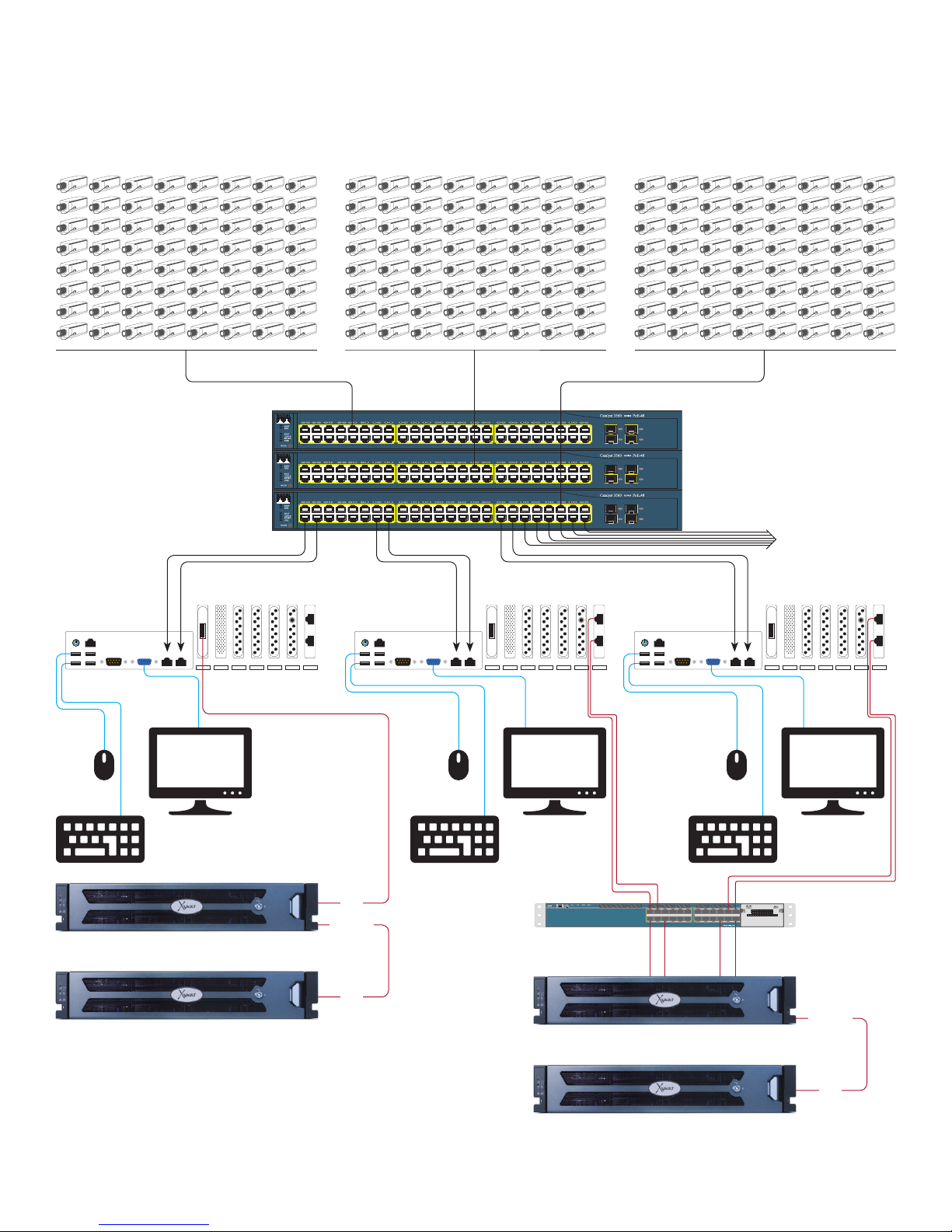
IV. Base Architecture And Connection Point Diagram ...................................................................................................................................................9
V. Getting Started
A. Drive Enclosure Slots And Trays ......................................................................................................................................................................12
i. Drive Tray Identification
ii. Drive Tray Removal
iii. Drive Tray Insertion
B. Cabling & Connections .......................................................................................................................................................................................13
C. Remote Access to Management GUI ............................................................................................................................................................. 15
D. Changing Camera / Viewing / Management Port IP Addresses .......................................................................................................... 16
E. Changing iSCSI/NAS Port IP Addresses ......................................................................................................................................................17
F. Default Username and Password ...................................................................................................................................................................18
VI. RAID Management
Using BIOS Control
A. Entering BIOS RAID Control .............................................................................................................................................................................19
B. Creating A Mirrored OS Drive Pair ...................................................................................................................................................................20
C. BAD Drive Rebuild/Restore ................................................................................................................................................................................24
Using MegaRAID Storage Manager
A. Accessing RAID Manager ..................................................................................................................................................................................25
B. Creating RAID Sets ..............................................................................................................................................................................................26
C. Mounting RAID Sets to Storage Server.........................................................................................................................................................30
D. Expanding RAID Sets ..........................................................................................................................................................................................32
E. Configuring Rebuild, Reconstruction & BGI Rates ...................................................................................................................................34
VII. Configuring Alerts .............................................................................................................................................................................................................. 35
VIII. Support..................................................................................................................................................................................................................................38
Appendix A Specifications ..........................................................................................................................................................................................................39
Appendix B Main Board connectors and jumpers ...............................................................................................................................................................41
Appendix C Revisions & BIOS Settings ...................................................................................................................................................................................44
Appendix D Field Replaceable Units (FRU) Parts................................................................................................................................................................47

xVault xNVR200/300/400 User Guide V2.0.0 4
NOTICE: First and most important level of data protection starts
with uninterruptable power. An Uninterruptable Power Source
(UPS) is required to protect storage data, cache battery backup
is not adequate to the task of data storage protection.
If this xNVR is not protected by an UPS please consult with your
account representative or pre-sales engineer for assistance in
correctly sizing a UPS to not only protect this xNVR but your en-
tire IT infrastructure.

xVault xNVR200/300/400 User Guide V2.0.0 5
I. PRODUCT INTRODUCTION
The xVault® xNVR200, xNVR300 and xNVR400 series is Seneca’s series of rack mount security and surveillance recording servers. The
200 and 300 series are a single processor recorder family and the 400 series is a dual processor recorder family.
The xVault Unified Storage series is available in five rack mount comfigurations.
2U 4 Bay 2U 8 Bay 2U 12 Bay 3U 16 Bay 4U 24 Bay
All units support SAS 3g and 6g, SATAII and III and Solid State Drives. The 2U rack form factor is available in 4, 8 and 12 bay configu-
rations. The 3U supports up to sixteen internal hot swap drives and the 4U supports up to twenty four internal hot swap drives. The
xVault xNVR’s are optionally expandable externally up to a maximum of 120 drives which is dependent on starting xNVR model.
The xNVR200 group is powered with the Intel® Xeon® processor E3 quad core. The xNVR300 and 400 groups are based on the Intel®
Xeon® processor E5 processor. All of the Seneca xNVR recording servers provide ample power to drive outstanding IO and bandwidth, op-
tions for more powerful higher core count processors are available to meet VMS demands. Memory options up to 256GB are also configu-
rable. The standard units ship with two 1Gbe network ports with options to support iSCSI or NAS connectivity.
Microsoft Windows graphical user interface allows easy configuration for advance features such as dynamic volume expansion, storage
virtualization and same enclosure mixed tier storage support.
xNVR200 xNVR300 xNVR400
Operating System support Linux, Windows 7 Professional, Server 2008 R2
CPU Intel® Xeon® Processor E3 Intel® Xeon® Processor E5 Dual Intel® Xeon® Processor E5
Max memory 16GB 32GB 64GB
Enhanced graphics standard standard standard
1GbE Camera LAN ports 111
1GbE Viewing & Management ports 111
Form Factor 2U 4 Bay, 2U 8 Bay, 2U 12 Bay, 3U 16 Bay, 4U 24 Bay
SSD OS drives option option option
Mirrored OS standard standard standard
DAS drive expansion option standard standard
Max number of drives 24 24 24
Max standard raw internal capacity 120TB 120TB 120TB
High speed storage option option option
iSCSI/NAS storage support option option option
Redundant Power standard standard standard

xVault xNVR200/300/400 User Guide V2.0.0 6
II. INTENDED AUDIENCE
The intended audience for this manual and product should have a working knowledge of server hardware, operating systems and be
able to configure network interfaces, switches and cameras to requirement.
Server Hardware/OS
• Base server layout concepts and the ability to recognize rear connections necessary for management, network or storage con-
nectivity.
• Know different PCIe slot mechanical and electrical differences and how to apply to proper use.
• Have a working knowledge of RAID concepts and application. Be able to use advanced RAID configuration utilities.
• Familiarity with SATA, SAS and SSD hard drives as well as internal and external cabling requirements.
• Be familiar with network connectivity and configuration of NIC cards with regard to IP addressing, teaming, jumbo frames and
MTU size.
• Able to read and do base level interpretation of system logs and error logs.
• Have a working knowledge of how to provide outside access via the Internet for remote technical assistance.
Network Hardware
• Have a clear understanding of LAN/WAN infrastructure and how to plan for additional servers, cameras and network storage
when required.
III. BEST PRACTICES
NETWORK SEGREGATION
Camera LAN, Management LAN and VIEWING LAN can coexist in the same sub structure. The video management software should pro-
vide “best practice” advice as to if and when the three LAN types should be separate.
Two 1GbE network ports should be used to provide path resiliency whenever possible.
iSCSI/NAS storage should connect to an isolated network dedicated strictly to storage. This separation allows for best performance
and protection. The standard xNVR configuration provide two 1GbE ports, a second network interface module with at least two ports
should be added if iSCSI or NAS storage is to be implemented.
NETWORK IP ADDRESSING FOR CAMERA, MANAGEMENT & VIEWING LAN
When camera LANs are created without the use of a DHCP server, it is recommended to use one of three non-routed IP address
ranges. These ranges are;
10.0.0.0 – 10.255.255.255
172.16.0.0 – 172.31.255.255
192.168.0.0 – 192.168.255.255
Servers, managed switches, directors, viewing stations or clients should consume upper IP addresses in a subnet, leaving lower IP
addresses for cameras. This creates a more easily recognized separation between IT hardware and cameras.
Seneca preconfigures standard LAN ports with DHCP disabled and uses starting addresses of 192.168.1.253 and 252 for the NIC
ports. All servers ship with the afore mentioned default addresses. When there is more than one server installed, the network ports must
be individually configured on each xNVR. The following table is provided for reference only and addresses are not required.

xVault xNVR200/300/400 User Guide V2.0.0 7
RECOMMENDED XNVR FIXED IP ADDRESSES
IP Address port 0 IP Address port 1 Mask Gateway
1st Server* 192.168.1.253 192.168.1.252 255.255.255.0 192.168.1.1
2nd Server 192.168.1.251 192.168.1.250 255.255.255.0 192.168.1.1
3rd Server 192.168.1.249 192.168.1.248 255.255.255.0 192.168.1.1
4th Server 192.168.1.247 192.168.1.246 255.255.255.0 192.168.1.1
5th Server 192.168.1.245 192.168.1.244 255.255.255.0 192.168.1.1
6th Server 192.168.1.243 192.168.1.242 255.255.255.0 192.168.1.1
7th Server 192.168.1.241 192.16831.240 255.255.255.0 192.168.1.1
8th Server 192.168.1.239 192.168.1.238 255.255.255.0 192.168.1.1
9th Server 192.168.1.237 192.168.1.236 255.255.255.0 192.168.1.1
10th Server 192.168.1.235 192.168.1.234 255.255.255.0 192.168.1.1
More than 10 servers or nodes (xNVRs or management servers) requires a domain control services (server)
* Default IP Addresses for all xNVR’s shipped
IP ADDRESSING iSCSI SAN
Seneca preconfigures the IP SAN address ports. This preconfiguration helps facilitate the connection of xVault USP and xVOS iSCSI
storage arrays to the xNVR.
Completely separate networks should be used when implementing an IP SAN. Seneca will always recommend or quote an extra NIC
card with a minimum of two 1GbE ports per server when cognoscente of the desire or requirement to support IP SAN storage.
The IP SAN should be isolated from general LAN or Camera LAN traffic either by “VLAN”ing in a switch or with a separate switch. This
isolation allows storage to perform as designed and adds a certain level of protection from external attack.
RECOMMENDED XNVR FIXED IP ADDRESSES FOR 1GBE IP ISCSI SAN
IP Address port 2 IP Address port 3 Mask Gateway
1st Server* 10.0.10.254 10.0.10.253 255.255.255.0 none
2nd Server 10.0.10.252 10.0.10.251 255.255.255.0 none
3rd Server 10.0.10.250 10.0.10.249 255.255.255.0 none
4th Server 10.0.10.248 10.0.10.247 255.255.255.0 none
5th Server 10.0.10.246 10.0.10.245 255.255.255.0 none
6th Server 10.0.10.244 10.0.10.243 255.255.255.0 none
7th Server 10.0.10.242 10.0.10.241 255.255.255.0 none
8th Server 10.0.10.240 10.0.10.239 255.255.255.0 none
9th Server 10.0.10.238 10.0.10.237 255.255.255.0 none
10th Server 10.0.10.236 10.0.10.235 255.255.255.0 none
More than 10 servers does not require a domain server for the IP SAN storage
* Default iSCSI IP address for all xNVR’s shipped

xVault xNVR200/300/400 User Guide V2.0.0 8
RAID SET CONFIGURATION CONSIDERATION & INFORMATION
Best RAID5 or RAID6 performance is when the drive count in a RAID set is between 12 and 24 drives. Eight drives in a RAID5/6
should be considered the lowest drive count when IO and transfer rates are above anything but the most basic.
When drive counts in a RAID set are below five, it is highly recommended to use RAID10. If the capacity is low enough a mirrored
(RAID1) solution using SSD drives can be considered as a higher performance option without extravagant expense. Please consult with
your account representative.
Unless otherwise specified, Seneca’s policy is to provide RAID5 when using less that 18 drives in the set. Eighteen to twenty four drives
will default to RAID6.
The xNVR series may be optionally configured to support direct attached external storage. This provides better performance than net-
work storage (iSCSI or NAS) at a significantly lower price point.
RAID REBUILD/RECONSTRUCTION PARAMETERS
Seneca leaves the rebuild and reconstruction parameters on the RAID controller at a factory default of 30% of total IO and Bandwidth
consumption. Customer preference of restore of defective drive versus impact on array performance which can result in frame drops is
subjective.
In house testing shows that with Rebuild and Reconstruction rates set to 20%. A replacement drive will rebuild at a rate of no more than
2.22 hours per terabyte for the drive being restored.
APPROXIMATE RAID MEMBER REBUILD TIME
Drive Size Four or Eight Drive RAID Set
1TB 2.22 hours
2TB 4.44 hours
3TB 6.66 hours
4TB 8.88 hours
5TB 11.1 hours
6TB 13.32 hours

xVault xNVR200/300/400 User Guide V2.0.0 9
IV. BASIC ARCHITECTURE AND CONNECTION POINT DIAGRAM
xNVR200
POE Switch Stack
To: remote
management and
viewing stations
Camera, Viewing and
Management LANs
Port 3
Port 4
Port 2Port 1
USB 3USB 1
USB 4USB 2
IPMI
VGA
Port 3
Port 4
Port 2Port 1
USB 3USB 1
USB 4USB 2
IPMI
VGA
Port 3
Port 4
Port 2Port 1
USB 3USB 1
USB 4USB 2
IPMI
VGA
UP
UP
UP
DOWN
DOWN
Direct Attached Storage Expansion
iSCSI SAN Storage
iSCSI SAN Switch
or Switch VLAN

xVault xNVR200/300/400 User Guide V2.0.0 10
xNVR300
POE Switch Stack
To: remote
management and
viewing stations
Camera, Viewing and
Management LANs
UP
UP
DOWN
DOWN
Direct Attached Storage Expansion
iSCSI SAN Storage
iSCSI SAN Switch
or Switch VLAN
IPMI
Port 2Port 1
USB 3USB 1
USB 4USB 2
Port 3
Port 4
VGA
IPMI
Port 2Port 1
USB 3USB 1
USB 4USB 2
Port 3
Port 4
VGA
IPMI
Port 2Port 1
USB 3USB 1
USB 4USB 2
Port 3
Port 4
VGA
UP

xVault xNVR200/300/400 User Guide V2.0.0 11
xNVR400
POE Switch Stack
To: remote
management and
viewing stations
Camera, Viewing and
Management LANs
UP
UP
DOWN
DOWN
Direct Attached Storage Expansion
iSCSI SAN Storage
iSCSI SAN Switch
or Switch VLAN
UP
IPMI
Port 2
Port 1
USB 3USB 1
USB 4USB 2
Port 3
Port 4
VGA
IPMI
Port 2
Port 1
USB 3USB 1
USB 4USB 2
Port 3
Port 4
VGA
IPMI
Port 2
Port 1
USB 3USB 1
USB 4USB 2
Port 3
Port 4
VGA

xVault xNVR200/300/400 User Guide V2.0.0 12
SLOT1
SLOT5
SLOT9
SLOT2
SLOT6
SLOT10
SLOT3
SLOT7
SLOT11
SLOT4
SLOT8
SLOT12
SLOT1 SLOT2 SLOT3 SLOT4
SLOT5 SLOT6 SLOT7 SLOT8
SLOT9 SLOT10 SLOT11 SLOT12
SLOT13 SLOT14 SLOT15 SLOT16
SLOT17 SLOT18 SLOT19 SLOT20
SLOT21 SLOT22 SLOT23 SLOT24
xNVR 2U 12 BAY
xNVR 4U 24 BAY
SLOT1 SLOT2 SLOT3 SLOT4
SLOT1
SLOT5
SLOT2
SLOT6
SLOT3
SLOT7
SLOT4
SLOT8
SLOT1
SLOT5
SLOT9
SLOT13
SLOT2
SLOT6
SLOT10
SLOT14
SLOT3
SLOT7
SLOT11
SLOT15
SLOT4
SLOT8
SLOT12
SLOT16
V. GETTING STARTED
A. Drive Enclosure Slots And Trays
Operating System (OS) drives are not front side hot swap accessible. 2U enclosures have the operating system disk mounted internally.
3U and 4U drives are rear mounted and hot swappable. The operating system drive may or may not come as a mirrored pair, this is
dependent on standard configuration and option availability.
Removable drives are installed beginning with SLOT 1 and continuing sequentially until all drive bays are filled. Drives installed from the
factory will be in groups of performance. Meaning, Solid State Drives will be installed first, followed by 15k RPM drives, followed by 10k
RPM drives then 7200 RPM drives. Future addition of drives does not require reordering drives; it is advised that additional drives be
added in order of performance. SSD and 7200 RPM drives are available with SATA interfaces, never mix SAS and SATA drives in the
same RAID set or group.
i. DRIVE TRAY IDENTIFICATION
All drive trays shipped from the factory will have a slot number ID affixed to the top front. Trays will be labeled whether drives
are installed or not.
xNVR 2U 4 BAY xNVR 3U 16 BAY
xNVR 2U 8 BAY

xVault xNVR200/300/400 User Guide V2.0.0 13
ii. REMOVING DRIVE TRAY
Press “Lever Release Button”. The tray “Extraction/Insertion Lever” will pop out on the right side. Gently rotate the lever out-
ward and at the same time cradle the drive tray underneath with your free hand. When the drive lever is fully extended, slide the
drive tray out of the enclosure.
iii. INSERTING DRIVE TRAY
Match tray number to enclosure slot number. With the lever fully extended, slowly slide the tray into the slot until lever engages en-
closure. Gently push drive lever in, the tray should slide into the enclosure without significant force on the lever or tray. Push lever
in until the lever release button locks, there should be a distinct “click” when this happens. If the lever does not move in at corre-
sponding rate as the tray slides into the enclosure, STOP! Pull the tray back out and try again. When the tray is correctly installed it
should be flush with all other trays in the enclosure.
NEVER move the tray in fast or force the lever to close. Damage will occur to the tray and possibly to the drive connector.
B. CABLING & CONNECTION
XNVR video recorder appliances come in three form factors but all use common components and cabling points. There are only six
main cabling groups;
• Power
• Monitor/Keyboard/Mouse
• Camera/Viewing/Management Network
• iSCSI/NAS Network (option)
• RAID Expansion Port (option on some models)
POWER CORDS
All xVault storage appliances come with redundant hot swap power supplies. Each power supply requires its own power cord. The
power cords supplied are standard 115VAC machine cords. Care should be taken to always route AC power cords away from cables
that transmit data.
It is also recommended that each power cord have a separate electrical path back to the facility service entrance. Meaning each
power cord should be connected to separate circuit breakers. It is also prudent to have at least one of the power cords connected to
an uninterruptable power source.
Lever Release Button
Extraction/Insertion Lever

xVault xNVR200/300/400 User Guide V2.0.0 14
Port 3
Port 4
iSCSI/NAS Ports
Optional Analog Capture Card
RAID Controller
Exp. Ser. Mgmt. 12/16/24 Bay Only
RAID Expansion Port
Port 2Port 1
USB 3USB 1
USB 4USB 2
Camera
LAN
Viewing and
Management
LAN
IPMI
VGA
IPMI
Port 2Port 1
USB 3USB 1
Mouse
Keyboard
USB 4USB 2
Exp. Ser. Mgmt. 12/16/24 Bay Only
Port 3
Port 4
iSCSI/NAS Ports
RAID Controller
VGA
RAID Expansion Port
PCIe x8 Optional Card
Optional 10 GbE NIC Port
Camera
LAN
Viewing and
Management
LAN
IPMI
Port 2
Port 1
USB 3USB 1
USB 4USB 2
Exp. Ser. Mgmt. 12/16/24 Bay Only
Port 3
Port 4
iSCSI/NAS Ports
RAID Controller
VGA
RAID Expansion Port Option
PCIe x8 Optional Card
Camera
LAN
Viewing and
Management
LAN
REAR SIGNAL CABLE LOCATIONS
xNVR200
xNVR300
xNVR400
NOTE: 2U depicted, 3U, and 4U have same connector and option locations, only the height of the PCIe cards is different.
Camera
LAN
Viewing and
Management
LAN
Camera
LAN
Viewing and
Management
LAN

xVault xNVR200/300/400 User Guide V2.0.0 15
MONITOR, KEYBOARD & MOUSE CONNECTIONS
A single video monitor may be connected to the HDMI OR DVI connector but not both. The two denoted USB ports are used for key-
board and mouse connection. These ports are KVM compatible.
CAMERA/VIEWING/MANAGEMENT NETWORK CONNECTIONS
The xNVRs use standard Cat 6 cabling. The xNVR’s come standard with two 10/100/1000 802.11 network ports. The ports ship
from the factory with the following fixed IP addresses;
IP ADDRESS MASK GATEWAY
Port 0 192.168.1.253 255.255.255.0 192.168.1.1
Port 1 192.168.1.252 255.255.255.0 192.168.1.1
NOTE: Each xNVR on the network must have a unique IP address.
ISCSI/NAS NETWORK CONNECTIONS
iSCSI and NAS connections use standard Cat6 cabling. The xNVR can be optionally equipped to support iSCSI/NAS external storage
appliances. iSCSI IP SAN storage requires the SAN be isolated for any other LAN or WAN. As such separate 1GbE ports are supplied to
support the IP SAN. It is highly recommended to use fixed non-routable IP addresses to support the IP SAN. For customer convenience,
the ports have the following default settings.
IP ADDRESS MASK GATEWAY
Port 2 10.0.10.254 255.255.255.0 blank
Port 3 10.0.10.253 255.255.255.0 blank
NOTE: Each IP SAN member on the storage area network must have a unique IP address.
RAID EXPANSION PORT CONNECTION
The xNVR can be optionally equipped with the ability to expand using direct attached storage enclosures. Up to four external drive en-
closures are supported. The interconnect cable used is an industry standard SFF8088 to SFF8088 cable. External chassis supplied
by Seneca come with the cable to connect to the xNVR.
C. REMOTE ACCESS TO THE MANAGEMENT GUI
All xNVRs have the ability to be remotely accessed for management. This is accomplished by using the Remote Desktop Connection
services. Any PC or Desktop running a Microsoft Operating System that is connected to the same subnet or directly connected to a
Camera/Viewing/Management Port 0 can remotely access the xNVR
Open the PC/laptop Remote Desktop Connection and enter the xNVR IP ad-
dress as shipped from the factory.
You will be prompted for the username and password of the system. Upon suc-
cessful entry the standard OS window will appear and navigation can proceed
as if using a directly attached monitor and keyboard.

xVault xNVR200/300/400 User Guide V2.0.0 16
D. CHANGING CAMERA/VIEWING/MANAGEMENT PORT IP ADDRESSES
Port attributes are accessed as follows;
Click on Start button located on the bottom left corner of the display.
1. Click on Control Panel
2. Click on Network and Internet
3. Click on Network and Sharing Center
4. Click on Change Adaptor Settings
5. Select the Camera or View_Mgmt port to be reviewed or
changed
6. Select Internet Protocol Version 4 (TCP/Ipv4)
7. Review or change IP information for the selected
port.
NOTE: Each Port must have a unique IP Address and the
same mask. Setting or features must be set the same for
each port.
1
2
3
4
6
7
5

xVault xNVR200/300/400 User Guide V2.0.0 17
E. CHANGING iSCSI/NAS PORT ATTRIBUTES
For iSCSI implementation it is highly recommend to leave the iSCSI ports at the factory shipped static IP port addresses.
NIC port attributes are accessed as follows;
Click on Start button located on bottom left corner of display.
1. Click on Control Panel
2. Click on Network and Internet
3. Click on Network and Sharing Center
4. Click on Change Adaptor Settings
5. Select the iSCSI/NAS port to be reviewed or changed
6. Select Internet Protocol Version 4 (TCP/Ipv4)
7. Review or change IP information for the selected
port.
1
2
3
4
6
5
7

xVault xNVR200/300/400 User Guide V2.0.0 18
F. DEFAULT USERNAME AND PASWORD
The system ships with two default users. Both share the same password and can be changed per policy.
Username: Administrator Password: P@ssw0rd
Username: NVR_Service Password: P@ssw0rd

xVault xNVR200/300/400 User Guide V2.0.0 19
VI. RAID MANAGEMENT
The intent of this section is to provide guidance in the creation and expansion of RAID sets within the xNVR and direct attached expan-
sion chassis.
The xNVR200, 300 and 400 families connect the OS drive to the embedded motherboard RAID controller. The VMS application(s)
also reside on the OS drive. Depending on appliance purchased and options selected the OS drive may consist of a mirrored pair. In the
cases where the OS drive is mirrored it is recommended that base management functions be done using the BIOS RAID controller tools.
The BIOS RAID controller tools are accessed by simultaneously hitting the Ctrl and M keys during power up while the following screen is
displayed on the console monitor.
It is recommended that the BIOS tools only be used for OS drive mirror set creation and rebuild/restore of a defective drive. To this end
only creation and rebuild/restore will be covered in this manual. All other functions, including rebuild/restore, can be done via the Mega-
RAID Software Manager (MSM) which can be found and launched from the Windows operating system desktop. Instruction for use of
the MSM can also be found in this manual.
The xNVR200, 300 and 400 families with 8 or more disk bays are supplied with a PCIe RAID controller. This PCIe RAID controller
maintains the array(s) that contain the video stream data and archives. Since the arrays can only be accessed while an operating system
is intact and operational and because control of the arrays is easier using the MegaRAID Software Manager (MSM) software, only the
MSM will be covered by this manual for PCIe based disks and arrays.
USING BIOS CONTROL FOR MIRRORED DRIVE SETS ONLY
A. ENTERING BIOS RAID CONTROL MENU
1. Power up system
2. During power up self-test wait for the following screen to appear. Immediately and simultaneously press the Ctrl and M keys
to enter the BIOS RAID routine.

xVault xNVR200/300/400 User Guide V2.0.0 20
When the following screen appears, the BIOS RAID
control has successfully been entered.
NOTE: DO NOT select Ctrl and H, this is not the OS
drive RAID control screen. Major damage to existing
video can occur.
B. CREATING A MIRRORED OS DRIVE PAIR
REMEMBER the system ships from Seneca with the operating system installed. This section is only provided in the event recovery
from a catastrophic event that destroyed the entire mirrored disk pair is required.
1. From the management screen select
Configure and Easy Configuration
2. From the ARRAY SELECTION MENU use
the up and down arrows to select the two
drives for the mirror set. Use the space key to
lock the desired drives.
This manual suits for next models
2
Table of contents
Other Seneca Server manuals