Senergy 2K User manual

Installation and Operation Manual
Applica :ble model 2K/3K/3.6K/4K/5K/6K
Version:00 Date:2021/06/02

Contents
U er ManualsC ntentso
Forward -----------------------------------------------------4
ApplicationModel-----------------------------------------------4
ApplicablePersonnel---------------------------------------------4
SymbolConventions---------------------------------------------5
1 Safety Precautions ------------------------------------------6
11PersonnelSafety---------------------------------------------6.
1 2 PV Inverter Protection - - - - - - - - - - - - - - - - - - - - - - - - - - - - - - - - - - - - - - - - - 6.
13InstallationSafety --------------------------------------------6.
1 4 Electrical Connections - - - - - - - - - - - - - - - - - - - - - - - - - - - - - - - - - - - - - - - - - 7.
1 5 Operating and Commissioning - - - - - - - - - - - - - - - - - - - - - - - - - - - - - - - - - - - - 7.
16Maintenance------------------------------------------------7.
1 7 Additional Information - - - - - - - - - - - - - - - - - - - - - - - - - - - - - - - - - - - - - - - - - - 8.
2Overview of the Inverter -------------------------------------9
21FunctionalModels--------------------------------------------9.
22NetworkApplication-------------------------------------------9.
2 3 Outline and Dimensions - - - - - - - - - - - - - - - - - - - - - - - - - - - - - - - - - - - - - - - 10.
24WorkingProcess--------------------------------------------12.
25WorkingModes---------------------------------------------13.
3Storage ---------------------------------------------------14
4Installation ------------------------------------------------15
4 1 Checking the Outer Packing- - - - - - - - - - - - - - - - - - - - - - - - - - - - - - - - - - - - - 15.
42Movingtheinverter-------------------------------------------16.
4 3 Identify the PV Inverter- - - - - - - - - - - - - - - - - - - - - - - - - - - - - - - - - - - - - - - - -16.
4 4 Installation Requirements - - - - - - - - - - - - - - - - - - - - - - - - - - - - - - - - - - - - - - 17.
4 5 Installing a Rear Panel - - - - - - - - - - - - - - - - - - - - - - - - - - - - - - - - - - - - - - - - -22.
4 6 Installing the Inverter - - - - - - - - - - - - - - - - - - - - - - - - - - - - - - - - - - - - - - - - - -24.

U er ManualsC ntentso
5 Electrical Connections--------------------------------------25
5 1 Connecting Protection Ground PGND Cables - - - - - - - - - - - - - - - - - - - - - - - - 25. ( )
5 2 Connecting AC Output Cables - - - - - - - - - - - - - - - - - - - - - - - - - - - - - - - - - - - 27.
5 3 Connecting the PV Strings - - - - - - - - - - - - - - - - - - - - - - - - - - - - - - - - - - - - - - 30.
5 4 Connecting Communication Cables - - - - - - - - - - - - - - - - - - - - - - - - - - - - - - - - 34.
5 5 Power limit (optional) - - - - - - - - - - - - - - - - - - - - - - - - - - - - - - - - - - - - - - - - - 35.
5 6 Installation Verification - - - - - - - - - - - - - - - - - - - - - - - - - - - - - - - - - - - - - - - - 38.
6 System Operation ------------------------------------------39
6 1 Powering ON the Inverter - - - - - - - - - - - - - - - - - - - - - - - - - - - - - - - - - - - - - - 39.
6 2 Powering OFF the Inverter - - - - - - - - - - - - - - - - - - - - - - - - - - - - - - - - - - - - - 39.
7 User Interface ---------------------------------------------40
7 1 LED specification definition - - - - - - - - - - - - - - - - - - - - - - - - - - - - - - - - - - - - - 41.
7 2 LCD automatic-page-turning display - - - - - - - - - - - - - - - - - - - - - - - - - - - - - - - 42.
7 3 LCD Warning display - - - - - - - - - - - - - - - - - - - - - - - - - - - - - - - - - - - - - - - - - 43.
8 Maintenance -----------------------------------------------44
81RoutineMaintenance -----------------------------------------44.
8 2 Inverter Troubleshooting - - - - - - - - - - - - - - - - - - - - - - - - - - - - - - - - - - - - - - - 45.
8 3 Removing the Inverter - - - - - - - - - - - - - - - - - - - - - - - - - - - - - - - - - - - - - - - - -47.
9 Warranty --------------------------------------------------48
91QualityTerms-----------------------------------------------48.
92LiabilityWaiver----------------------------------------------48.
10 Disposal of the Inverter ------------------------------------49
11 Technical Specifications ------------------------------------50

4
Forward
Dear User,
Thank you so much for your choosing 2K-6K the latest generation of grid tied PV Strings, -
inverter hereinafter referred to as the inverter) designed and developed by the company( .
This user manual introduces the inverter in terms of its installation electrical connections, ,
, , , .operation commissioning maintenance and troubleshooting Please read through the manual
carefully before installing and using the inverter and keep the manual well for future reference, .
Grid tied PV string inverter-
Application Model
This user manual is intended for photovoltaic (PV) inverter operating personnel and qualified
electrical technicians.
Applicable Personnel
This user manual is subject to change specific please in kind prevail without prior notice( ) .
Notes:
2K/3K/3.6K
4K/5K/6K
U er ManualsForward
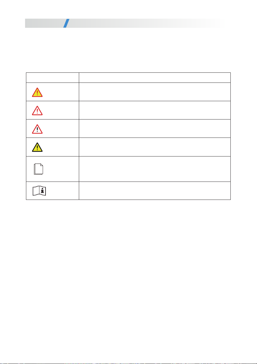
Indicates an imminently hazardous situation which if not correctly,
followed will result in serious injury or death, .
Indicates a potentially hazardous situation which if not correctly,
followed could result in serious injury or death, .
Indicates a potentially hazardous situation which if not correctly,
followed could result in moderate or minor injury, .
Indicates a potentially hazardous situation which if not correctly,
followed could result in equipment failure or property damage, , .
Calls attention to important information best practices and tips, :
supplement additional safety instructions for your better use of the
PV inverter to reduce the waste of your resource.
Refer to documentation (Remind operators to refer to the
documentation shipped with the inverter).
Symbol Conventions
Safety symbols used in this manual which highlight potential safety risks and important safety,
information are listed as follows, :
Symbol Description
WARNING
CAUTION
DANGER
NOTICE
NOTE
REFER
5
U er ManualsForward

1 Safety Precautions
Before using the product please read these safety precautions in User Manual carefully, .
a. The PV inverter must be installed electronically connected operated and maintained through, ,
specially trained technician;
b The qualified technician must be familiar with the safety regulations of electrical system. ,
working process of PV power generation system, and standards of local power grid;
c. The technician must read through this User Manual carefully and master it before any operation.
1 1 Personnel Safety.
a Do not tamper with any warning signs on the inverter enclosure because these signs contain.
important information about safe operation.
b Do not remove or damage the nameplate on the inverter’s enclosure because it contains.
important product information.
1 2 PV Inverter Protection.
a Ensure there is no electronical connections around ports of the PV inverter before installation. ;
. .b Adequate ventilation must be provided for inverter installation location Mount the inverter in
vertical direction, and ensure that no object is put on the heat sink affecting the cooling. (For
details, refer to Chapter 4 Installation)
1 3 Installation Safety.
As soon as receiving the PV inverter please check if it is damaged,
during its transportation If yes please contact your dealer immediately. , .
Please read the User Manual carefully before installing the PV inverter;
warranty or liability will be exempted from the company if damage is
caused by installation faults.
NOTICE
NOTICE
6
U er ManualsSafety Precautions
a Input terminals of the PV inverter apply only to input terminals of PV String do not connect. ;
any other DC source to the input terminals.
b Before connecting PV modules ensure that is its voltage is within the safe range when. , ;
exposed to any sunlight, PV modules can generate high voltage.
c All electrical connections must meet the electrical standards of the country or region. .
. , ,d Cables used in electrical connections must be well fixed under good insulation and with
appropriate specification.
1 4 Electrical Connections.
A. Before getting the permission of electrical power authority in the country/region, the grid-
tied PV inverter cannot start power generation.
b Follow the procedures of commissioning described in the user manual when commissioning.
the PV inverter.
c Do not touch any other parts surface except the DC switch when the PV inverter is operating. ' ;
its partial parts will be extremely hot and can cause burns.
1 5 Operating and Commissioning.
1 6 Maintenance.
Before installing the inverter check all electrical ports to ensure no,
damage and no short circuit Otherwise personal casualty and or fire. /
will occur.
While the inverter operating high voltage can lead to an electrical,
shock hazard and even cause personal casualties Therefore, . ,
operate the PV inverter strictly according to the safety precautions in
the user manual.
Power OFF all electrical terminals before the inverter maintenance;
strictly comply with the safety precautions in this document when
operating the inverter.
DANGER
DANGER
DANGER
7
When the photovoltaic array is exposed to light, it supplies DC
voltage to the PCE.
WARNING
U er ManualsSafety Precautions

a For personal safety maintenance personnel must wear appropriate personal protective. ,
equipment (like insulation gloves and protective shoes) for the inverter maintenance.
b Place temporary warning signs or erect fences to prevent unauthorized access to the.
maintenance site.
c Follow the procedures of maintenance stipulated in the manual strictly. .
. ;d Check the relevant safety and performance of the inverter rectify any faults that may
compromise the inverter security performance before restarting the inverter.
1 7 Additional Information.
To avoid any other unforeseeable risk, contact immediately,your dealer
if there is any issue found during operation.
NOTICE
8
U er ManualsSafety Precautions
2 Overview of the Inverter
This chapter introduces the inverter and describes its functional model network application, ,
, , .appearance dimensions and working process etc
2 1 1 Function. .
This series is a single-phase grid-tied PV string inverter transformer less that converts the DC( )
power generated by PV strings into AC power and feeds the power into power grid.
Figure 2 1 shows a model number of the inverter using 3K as an example. , .
3K
Power class code
Figure 2 1 Model number descriptions.
2 1 Functional Models.
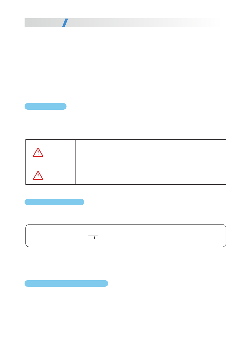
The series applies to grid-tied PV power systems for outdoor power stations. Typically, a grid-tied
PV power system consists of PV modules, grid-tied inverters, AC distribution units, and low-voltage
power grid, as shown in Figure 2.2.
2 2 Network Application.
The inverter is transformerless Add an isolation transformer before.
grounding the positive negative terminal of PV modules like Thin/ (
Film module for operation) .
Do not connect PV modules in parallel to several PV inverters for
operation.
WARNING
WARNING
9
U er ManualsOverview of the Inverter
2 1 2 Model Description. .
2 2 1 Grid-tied PV Power Systems. .
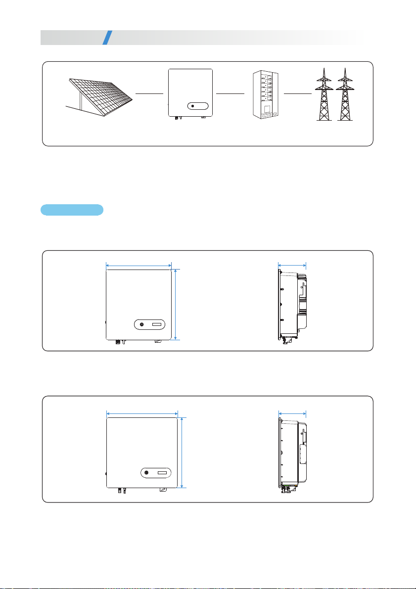
2 3 1 Outline. .
Figures 2 3 to 2 7 show the outline of the inverters as follows. . :
2 3 Outline and Dimensions.
Figure 2 2 a low-voltage grid-tied PV power system.
PV strings inverter AC Distribution Unit low-voltage power grid
Figure2.4 4K-6K PV Inverter with Dual MPPT Input unit mm( : )
Figure2.3 2K-3.6K PV Inverter with Single MPPT Input unit mm( : )
10
320mm
344mm
137mm
350mm
347mm
137mm
U er ManualsOverview of the Inverter

Figure 2 7 The bottom view of this series of inverter.
Figure 2 5 The front view and amplification effect of LED indicator area.
2K-3.6K PV Inverter with Single M PP T Input 4K-6K P V Inverter with Dual MPPT Input
Figure 2 6 The rear view of this series of inverter.
11
1. PV input connectors
2. COM2(RS-485/meter/CT/DI)
3. COM1(WIFI/GPRS/Ethernet/ RS-485)
4. AC output connector
5. External protec!on ground interface
6. Vent valve
7. DC isola!on switch
LED LCD(op!onal)
1234
5
6
72~3.6K 4~6K
1234
5
6
7
U er ManualsOverview of the Inverter
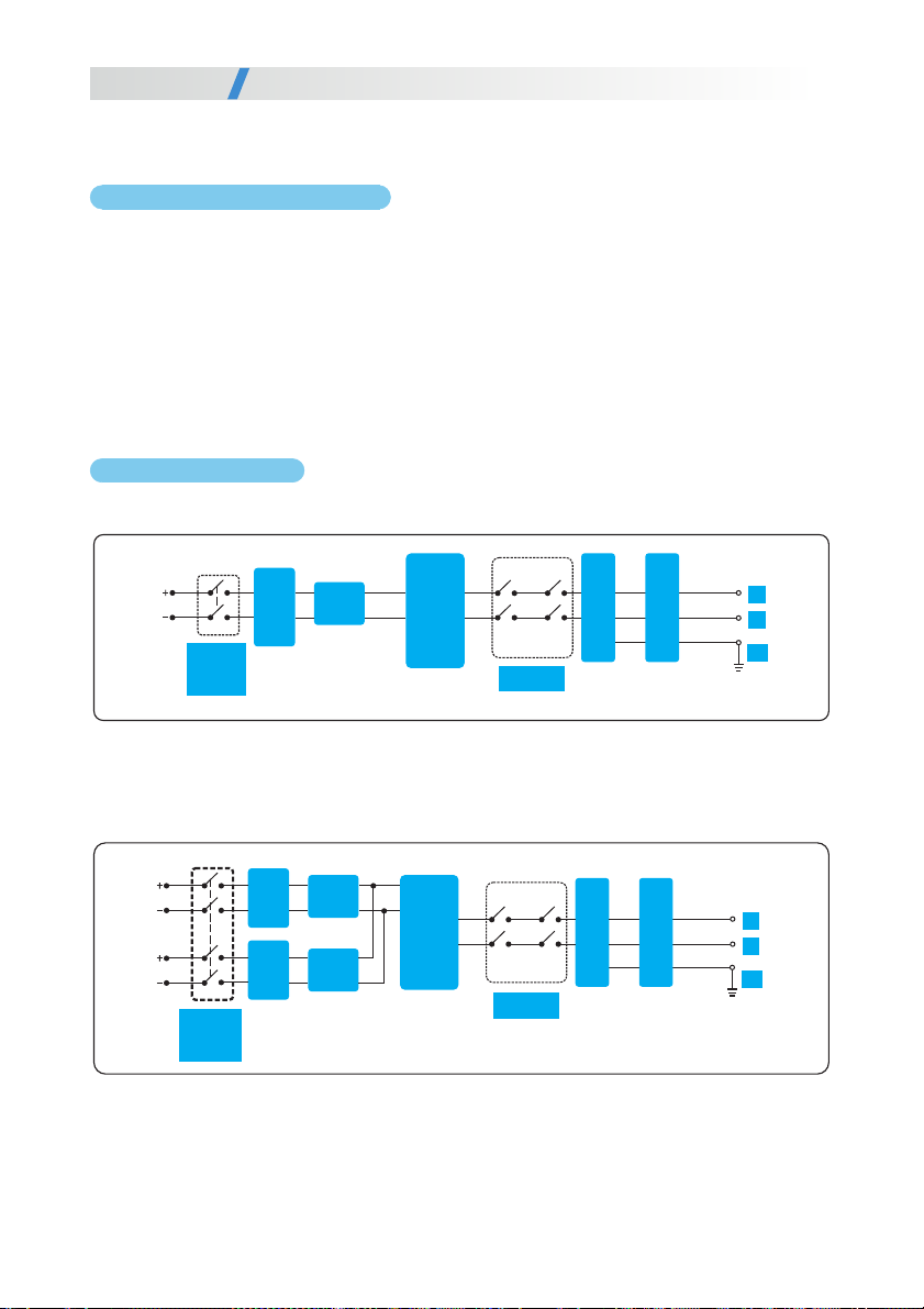
2 4 Working Process.
The 4K-6K PV Inverter with Dual MPPT Input receives input from two strings of PV panel (2K-
3.6K PV Inverter with Single MPPT Input receives input from only one string of PV panel).
Then the inputs are grouped into two independent MPPT routes inside the inverter to track the
maximum power point of the PV panel. The two MPPT power is then converted into DC Bus,
then the DC power is converted to AC power through an inverter circuit. Finally the AC power
is fed to the Power grid. EMI filer is used on both the DC and AC sides to reduce the
electromagnetic inference; Surge protection is supported on AC side.
Figure 2.8 shows the circuit diagram for the 2K-3.6K PV Inverter with Single MPPT Input:
Figure 2.9 shows the circuit diagram for the 4K-6K Inverter with Dual MPPT Input:
Figure 2.8 circuit diagram
Figure 2.9 circuit diagram
DC
EMI
Filter
1
MPPT
Route
Inverter circuit
AC EMI Filter
Relay
L
N
PE
AC surge
protector
PV DC
Switch
DC
EMI
Filter
1
MPPT
Route1
Inverter circuit
AC EMI Filter
PV DC
Switch
Relay
L
N
PE
MPPT
Route2
AC surge
protector
DC
EMI
Filter
2
12
U er ManualsOverview of the Inverter
2 4 1 Basic principle Description. .
2 4 2 Circuit Diagrams. .
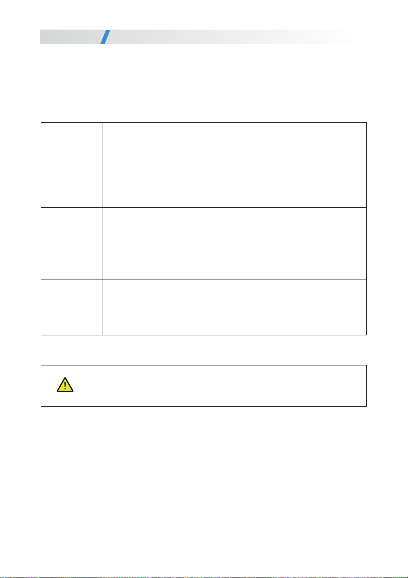
Table 2 1 Working modes description.
2 5 Working Modes.
Three working modes of the inverter are shown as follows standby operating and shutdown: , , .
. .Table 2 1 shows the conditions for the inverter to switch between working modes
The PV inverter enters the standby mode when
the input voltage of PV Strings can enable auxiliary power supply to run> ,
but cannot meet the inverter operation requirements.
the input voltage of PV Strings can meet the inverter to start requirements> - ,
.but cannot meet its minimum power requirements
When the PV inverter is grid tied and generates electricity it- ,
tracks the maximum power point to maximize the PV String output> .
>converts DC power from PV strings into AC power and feeds the power
to the power grid.
The PV inverter will enter to the shutdown mode if detecting a fault or a
shutdown command.
Modes
Standby
Operating
Description
The PV inverter switches from standby or operating mode to shutdown
mode if detecting a fault or a shutdown command.
The inverter switches from shutdown mode to standby mode if receiving
a Startup command or detecting that a fault is rectified.
Shutdown
13
instructions: if the equipment is used in a manner not specified
by the manufacturer, the protection provided by the equipment may
be impaired.
NOTICE
U er ManualsOverview of the Inverter

3 Storage
This chapter describes the storage requirements for the inverter.
The following storage instructions apply if the PV inverter will not be deployed immediately:
> .Do not unpack the inverter (put desiccant in the original box if the PV inverter is unpacked)
> ℃ ℃Store the PV inverter at a temperature range of -25 to +60 and with the relative humidity
of 0% to 100% (no condensing).
The PV inverter should be stored in a clean and dry place and be protected from dust and>
water vapor corrosion.
2K-3.6K PV Inverter with Single MPPT Input a maximum of eight layers of inverters can be>
stacked 4K-6K PV Inverter with Dual MPPT Input a maximum of six layers of inverters,
can be stacked.
> , , , .Do not position the inverter at a front tilt excessive back tilt or side tilt or upside down
> .Conduct periodic inspection during storage Replace the packing materials immediately if any
rodent bites are found.
Ensure that qualified personnel inspect and test the inverter before use if it has been stored>
for a long time.
14
U er ManualsStorage

4 Installation
4 1 Checking the Outer Packing.
a When receiving the inverter check that the packing materials are intact. , .
. , , ,b After unpacking check that the deliverables are complete intact and consistent with your
order list.
c Examine the PV inverter and its fittings for damage such as scraps and cracks. .
Do not install the inverter in a place where personnel are likely to
come into contact with its enclosure and heat sinks to avoid electrical
shock/burn.
Figures 4 1 The deliverables: The inverter and its fittings.
CAUTION
DANGER
15
U er ManualsInstallation
Do not install the inverter on flammable building materials or in an
area where flammable or explosive materials are stored.
or or
or
G
Items
A
B
C
D
E
F
G
H
Deliverables
The inverter
Rear panel
AC output connector
File package
DC terminal connector group
Screws
Removal tool for DC connector
Expansion screw group
(reserved for !ghtening the support and rear panel)
H

horizontally Hold the handles on both sides of the inverter as shown in Figure 4 2. , . .
Figure 4 2 Moving the inverter.
>Do not place the PV inverter with its wiring terminals contacting the
floor because the power ports and signal ports at the bottom of the
device are not designed to support the weight of the inverter.
> ,When placing the inverter on the floor horizontally put foam or
paper under to protect its enclosure.
4 3 1 Nameplate. .
After moving the PV inverter from packing box identify it by reading its nameplate labeled on,
the side of the inverter The nameplate contains important product information the model. :
information communications technical specifications and compliance symbols, / , .
4 3 Identify the PV Inverter.
CAUTION
If any damage mentioned above is found contact the dealer,
immediately.
4 2 Moving the inverter.
After checking the outer packing move the PV inverter to the designated installation position,
NOTICE
16
PV modules for non-isolated inverters. Non-isolated inverters shall
be provided with installation instructions that require PV modules
that have an IEC 61730 Class A rating. If the maximum AC mains
operating voltage is higher than the PV array maximum system
voltage then the instructions shall require PV modules that have a
maximum system voltage rating based upon the AC mains voltage.
NOTICE
U er ManualsInstallation

4 3 2 Compliance and Safety Symbols. .
Electrical shock!
There are residual voltages in the PV inverter It needs 5 minutes.
to finish discharge.
5mins
The PV inverter must not be touched when in operation Its.
enclosure and heat sinks are extremely hot.
Electrical shock! This part is charged Only qualified and/or trained.
electrical technicians are allowed to perform operations on the inverter.
If the inverter service life has expired dispose it in accordance with,
local rules for disposal of electrical equipment waste Do not dispose.
the PV inverter with household garbage.
The PV inverter is compliant with TUV.
Safety symbol Description
Applies to wall-mounting installation, as described below in detail.
Basic Requirements
a The inverter is protected to IP65 and can be installed indoors or outdoors. .
b The installation method and position must be appropriate for the weight and dimensions of.
the inverter.
c Do not install the inverter in a place where personnel are likely to come into contact with its.
enclosure and heat sinks because these parts are extremely hot during operation.
d Do not install the inverter in an area that stores flammable or explosive materials. .
a The ambient temperature must be below 50 t ensure the inverter’s optimal operation. ℃ o
and extend its service life.
Installation Environment Requirements
4 4 1 Determining the Installation Position. .
4 4 Installation Requirements.
17
U er ManualsInstallation
b The inverter must be installed in a well ventilated environment to ensure good heat dissipation. .
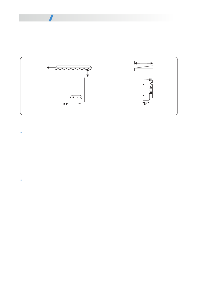
c The inverter must be free from direct exposure to sunlight rain and snow to extend its service. , ,
life. It is recommended that the inverter be installed in a sheltered place. If no shelter is
available, build an awning, as shown in Figure 4.3.
Figure 4 3 Installation environment with awning unit mm. ( : )
Carrier Requirements
Installation Space Requirements
a It is recommended that the inverter be installed at eye level to facilitate operation and.
maintenance.
b Reserve enough clearance around the inverter to ensure sufficient space for installation.
and heat dissipation, as shown in Figure 4.4.
a The carrier where the inverter is installed must be fire-proof Do not install the inverter on. .
flammable building materials.
b The wall must be solid enough to bear the weight of the inverter. .
c Do not install the inverter on a wall made of gypsum boards or similar materials with weak.
sound insulation to avoid noise disturbance in a residential area.
the front view
Awning
the lateral view
≥500
≥1000
18
U er ManualsInstallation
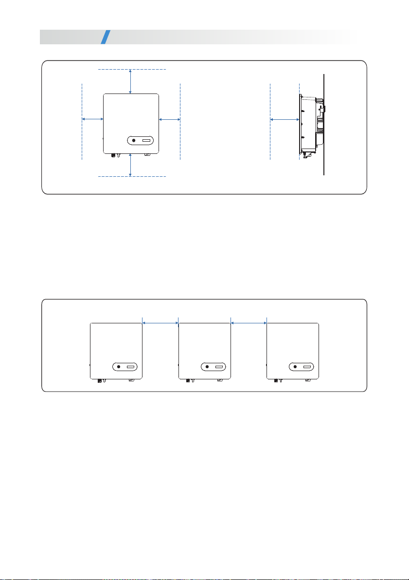
the front view the lateral view
Figure 4 4 Installation Space Requirements unit mm. ( : )
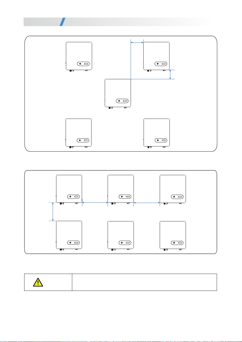
c When installing multiple inverter, install them along the same line (as shown in Figure 4.5) if.
sufficient space is available, and install them in triangle mode (as shown in Figure 4.6) or in
stacked mode (as shown in Figure 4.7) if no sufficient space is available. The installation
modes ensure sufficient space for installation and heat dissipation.
Figure 4 5 Installation along the same line unit mm. ( : )
>500
>500
>600
>150 >150
150 150
19
U er ManualsInstallation
150
1000
100
300
Figure 4 6 Installation in triangle mode (unit: mm).
Figure 4 7 Installation in stacked mode (unit: mm).
The clearance between multiple inverters must be increased to
ensure proper heat dissipation when they are installed in a hot area.
NOTICE
150
20
U er ManualsInstallation
This manual suits for next models
5
Table of contents
Other Senergy Inverter manuals


Popular Inverter manuals by other brands


Power Drive
Power Drive PD1000 user manual

Omega
Omega OTEC IEWQ Series installation manual

oventrop
oventrop OKF Series Installation and operating instructions

Western Co
Western Co W-HPT-30K user manual

Beghelli
Beghelli Vesta-M Micro Installation and operation instructions

Parker
Parker MA3 Series user manual


