Senergy 5K US User manual

USER MANUAL
ESS Inverter

HISTORY
VERSION ISSUED COMMENTS
1.0 03-Feb.-23 First release
Preface
WARNING
CAUTION
DANGER
NOTICE
NOTE
Scope
This manual is applicable to following inverters:
5K US
6K US
8K US
10K US
About This Manual
This manual describes the installation, connection, the use of APP, commissioning and maintenance
etc. of ESS inverter. Please first read the manual and related documents carefully before using the
product and store it in a place where installation, operation and maintenance personnel can access it
at any time. The illustration in this user manual is for reference only. This user manual is subject to
change without prior notice. (Specific please in kind prevail.)
Target Group
ESS inverters must be installed by professional electrical engineers who have obtained relevant
qualifications.
Conventions
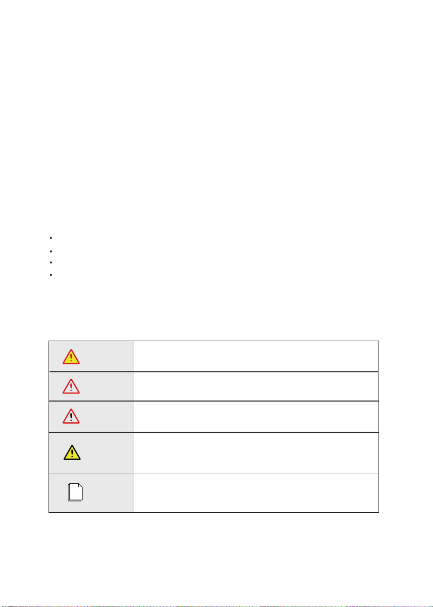
The following safety instructions and general information are used within this user manual.
Indicates an imminently hazardous situation which, if not correctly
followed, will result in serious injury or death.
Indicates a potentially hazardous situation which, if not correctly
followed, will result in serious injury or death.
Indicates a potentially hazardous situation which, if not correctly
followed, could result in moderate or minor injury.
Indicates a potentially hazardous situation which, if not correctly
followed, could result in equipment failure to run, or property
damage.
Call attention to important information, best practices and tips:
supplement additional safety instructions for your better use of the
Three phase hybrid inverter to reduce the waste of you resource.
ESS Inverter User Manual 3

CONTENTS
Preface
1. Safety
2. Product Introduction
3. Installation
4. Electrical Connection
5. System Operation
About This Manual
Target Group
Scope
Conventions
1.1 Symbols Used
1.2 Safety Precaution
2.1 Overview
2.2 Product Appearance
2.3 Model Definition
3.1 Packing List
3.2 Selecting the Mounting Location
3.3 Mounting
4.1 Grounding
4.2 Meter/CT Connection
4.3 Communication Connection
5.1 Inverter Working Mode
5.2 Startup/Shutdown Procedure
4 ESS Inverter User Manual

6. Commissioning
7. User Interface
8. Maintenance
9. Technical Specifications
6.1 Inspection
6.2 Commissioning Procedure
7.1 LED
7.2 App Setting Guide
8.1 Routine Maintenance
8.2 Inverter Troubleshooting
ESS Inverter User Manual 5
Before using the inverter, please read all instructions and cautionary markings on the unit and manual.
Put the instructions where you can take them easily.
The ESS inverter of ours strictly conforms to related safety rules in design and test. Local safety regulations
shall be followed during installation, operation and maintenance. Incorrect operation work may cause injury
or death to the operator or a third party and damage to the inverter and other properties belonging to the
operator or a third party.
Danger of high voltage and electric shock!
Only qualified personnel may perform work on the inverter.
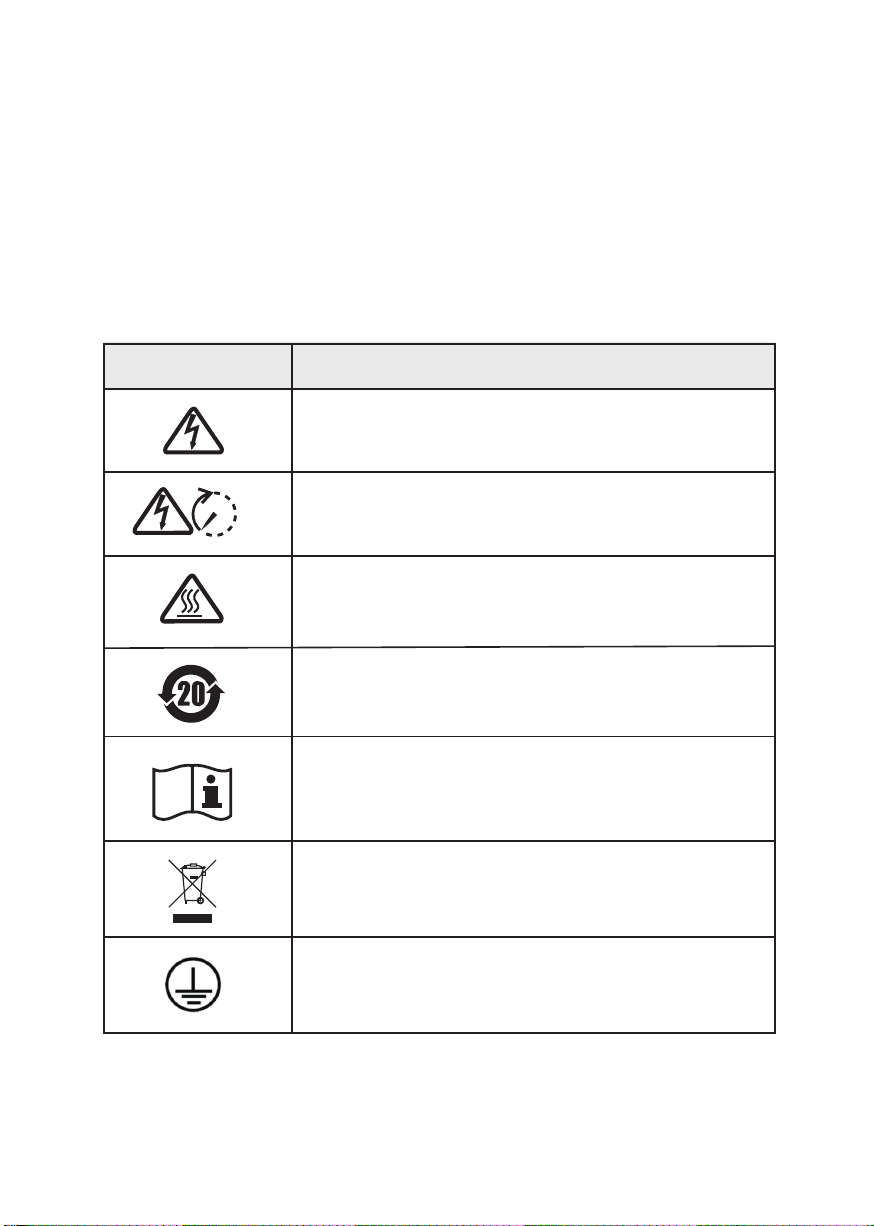
Grounding terminal
1.1 Symbols Used
Safety Symbol Description
Danger of high voltage. Residual voltage in the inverter need
5 mins to discharge, wait 5 mins before operation.
Danger of hot surface
Product should not be disposed as household waste.
5 mins
Environmental Protection Use Period
Refer to the operating instructions
Safety
1. Safety
6 ESS Inverter User Manual

Don’t connect Three phase hybrid inverter in the following ways:
BACKUP Port should not be connected to grid;
The single PV panel string should not be connected to two or more inverters.
1.2 Safety Precaution
Installation,maintenance and connection of inverters must be performed by qualified personnel, in
compliance with local electrical standards, wiring rules and requirements of local power authorities
and/or companies(for example: AS 4777 and AS/NZS 3000 IN Australia).
To avoid electric shock, DC input and AC output of the inverter must be terminated at least 5 minutes
before performing any installation or maintenance.
The temperature of some parts of the inverter may exceed 60℃ during operation. Do not touch the
inverter during operation to avoid being burnt.
Ensure children are kept away from inverters.
Don’t open the front cover of the inverter. A part from performing work at the wiring terminal (as
instructed in this manual), touching or changing components without authorization may cause injury
to people, damage to inverters and annulment of the warranty.
Static electricity may damage electronic components. Appropriate method must be adopted to prevent
such damage to the inverter; otherwise the inverter may be damaged and the warranty annulled.
Ensure the output voltage of the proposed PV array is lower than the maximum rated input voltage of
the inverter; otherwise the inverter may be damaged and the warranty annulled.
When exposed to sunlight, the PV array generates dangerous high DC voltage. Please operate according
to our instructions, or it will result in danger to life.
PV modules should have an IEC61730 class A rating.
If the equipment is used in a manner not specified by the manufacturer, the protection provided by the
equipment may be impaired.
Completely isolate the inverter before maintaining. Completely isolate the inverter should: Switch off
the PV switch, disconnect the PV terminal, disconnect the battery terminal, and disconnect the AC
terminal.
Prohibit inserting or pulling the AC and DC terminals when the inverter is running.
In Australia, the inverter internal switching does not maintain the neutral integrity, neutral integrity must
be addressed by external connection arrangements.
In Australia, the output of backup side in switchbox should be labeled main switch UPS supply, the
output of normal load side in switchbox should be labeled mains switch inverter supply.
Safety
ESS Inverter User Manual 7

The hybrid inverters are high-quality inverter which can convert solar energy to AC energy and store
energy into battery.
The inverter can be used to optimize self consumption, store in the battery for future use or feed into
public grid. Work mode depends on PV energy and user’s preference. It can provide power for emergency
use during the grid lost by using the energy from battery and inverter (generated from PV).
Monitoring
Device
Cloud
PV
ESS Inverter
BACKUP
Sensor Grid
2.1 Overview
ESS Inverter Application System
ESS Inverter
Product Introduction
Battery
2. Product Introduction
Normal Load
8 ESS Inverter User Manual
Smart
Load
On-Grid
Inverter
Generator
or
or
1314 16 17 19 21 24 25
1 4 7 10
3 6 9 10

The External View of ESS Inverter
2.2 Product Appearance
LED Details
Width(mm) Depth(mm)
420 800 240
LED Indicators PV BAT GRID EPS(BACKUP) COM ALARM
Product Introduction
Height(mm)
420.0
800.0
ESS Inverter User Manual 9
240.0
2.2.1 ESS Inverter

1. Battery Connect Terminals
2. PV Input Terminals
3. COM1/2/3 Ports (RS485, BMS,
DRM, CT, DRY, RSD, PARA)
4. COM Port (WIFI/GPRS)
5. Grounding Terminal
6. GRID Output Terminal
7. BACKUP Terminal
8. GEN Terminal
The Bottom View of ESS inverter
Product Introduction
10 ESS Inverter User Manual
3456
8
12
7
1. PV Switch
2. Toggle Latch ( for opening/closing
the junction box cover)
3. ON/OFF Button
The Left View of ESS Inverter
1
2
2
3

After unpacking, please check the following packing list carefully for any damage or missing parts. If
any damage or missing parts occurs, contact the supplier for help.
Number Quantity Description
3.1 Packing List
3. Installation
Installation
ESS Inverter User Manual 11
1 2 3 4 5 6 7 8 9
1 2 3 4
1 2 3 4 1 2 3 4
A B C D E F
G H I J
A 1 Inverter
B 1 Mounting bracket
C 1 File package
D 1 Meter (Optional)
E 2 CT
F
3 M6 Expansion screws
G
1
M6 Security screw
H
1
GPRS/WIFI/LAN module (Optional)
I
1 9-Pins terminal
J
3
4-Pins terminal
or or
1314 16 17 19 21 24 25
1 4 7 10
3 6 9 10

3.2 Selecting the Mounting Location
a. The storage inverter protection class is IP65 and can be mounted indoors or outdoors.
b. The
mounting location must be inaccessible to unrelated personnel since the enclosure and heat sinks
are extremely hot during operation.
c. Do not install the storage inverter in areas containing highly flammable materials or gases.
d. To ensure optimum operation and long service life, the ambient temperature must be below 50℃.
e. The
storage inverter must be mounted in a well ventilated environment to ensure good heat dissipation.
f. To ensure long service life, the storage inverter must not be exposed to direct solar irradiation, rain,
or snow. It is recommended that the inverter be mounted in a sheltered place.
g. The
carrier where the inverter is mounted must be fire-proof. Do not mount the inverter on flammable
building materials.
h. Do not install the inverter in a rest area since it will cause noise during operation.
i. The installation height should be reasonable and make sure it is easy to operate and view the display.
j. Product label and warning symbols shall be clear to read after installation.
k. Please avoid direct sunlight, rain exposure, snow cover.
3.2.1 Installation Environment Requirements
Installation
12 ESS Inverter User Manual
No direct sunlight No rain exposure No snow cover
Snow cover
Direct sunlight Rain exposure

3.2.2 Mounting Requirements
Mount the inverter vertically or tilted backward by max 15°. The device can not be installed
with a wrong mode and the connection area must point downward.
3.2.3 Installation Space Requirements
To ensure the inverter normally and easy to operate, there are requirements on available spaces of the
inverter, e.g. to keep enough clearance. Refer to the following figures.
Above: 500mm
Below: 500mm
Front: 1000mm
Left side: 350mm
Right side: 350mm
Installation along the same line for multiple inverter
350mm 350mm
Installation
ESS Inverter User Manual 13
≥350
≥500
≥350
≥500
≥1000
Upright Lean back ≤15° Horizontal
≤15°
Upside-down

Before mounting the inverter, you have to prepare
expansion screws and a security screw.
Step 1. Install the mounting bracket
Step 2. Install the inverter on the mounting bracket. Then lock the inverter using the security
screw. Refer to Figure e, Figure f.
Before drilling the hole on the wall, ensure no damage on the electric wire
and/or water pipe inside the wall.
DANGER
To prevent potential damages and injuries from inverter falling down,
please hang the inverter on the bracket, do not loosen grip unless confirm
that the inverter is well mounted.
CAUTION
3.3 Mounting
1. Use a level ruler to mark the position of the 3 holes on
the wall. Refer to Figure a. And drill 3 holes, 16mm in
diameter and 55mm in deep. Refer to Figure b.
2.
Knock the expansion screw kit into the hole together
with a hammer. Refer to Figure c.
Note: Do not remove the nut unit in this step.
3. After tightening 2-3 buckles, the expansion bolts are
tight and not loose, and then unscrew the bolts, spring
washer, gasket. Refer to Figure c.
4. Install and fix the mounting bracket on the wall.
Refer to Figure d.
Unit: mm
Installation
14 ESS Inverter User Manual
666
14
16
16
14
246.6
333
110.6 57 60
∅16
552
Drill the holes.
Mark the holes position
on the wall.
Hold the wall bracket horizontally.
M6 Security screw;
2.5N·m
Install the expansion tubes.
(M63 suites)
A B C D
Expansion screw group
C & D
Install the inverter.
Ø16mm; Depth: 55mm
A & B
M6
2.5N·m
c
e
b
a
df

Electrical Connection
This chapter shows the detailed connections of ESS inverter. The following illustration only uses the hybrid
inverter as an example.
ESS inverter system connection diagram:
Non-parallel connection mode
4. Electrical Connection
Ensure that inverter and all cables to be installed are completely powered
off during whole installation and connection. Otherwise, fatal injury can
occur due to the high voltage.
DANGER
Split phase (120/240Vac) connection diagram (US)
RSD
DRM
PARA
RS485
DRY METER BMS
COM
L1
L2
N
PE
13 14 16 17 19 21 24 25
1 4 7 10
3 6 9 10
25
24
1 4 10
3 6 10
Grid
Meter
or
CT
Normal Load
CT1
CT2
+ -
PVArray
Lithium battery/
lead-acid battery
DRY
1 2 3 4 5 6 7 8 9
Pin1 2
Pin Function
Pin1 Generator Control
Pin2 Generator Control
②
①
③
Smart
Load
On-Grid
Inverter
Generator
or
or
DRY
Critical Load
Breaker
Flow from grid
to inverter
ESS Inverter User Manual 15

16 ESS Inverter User Manual
Electrical Connection
Grid
Split Phase parallel connection mode-Scheme A (N=2)
①
Parallel communication connection
②
CT/Meter communication connection
③
BMS communication connection
*These communication cables can be connected
to any inverter, but they must be inserted into the
same inverter and we call this inverter No. 1 inverter.
RSD
DRM
PARA
RS485
DRY METER BMS
RSD
DRM
PARA
RS485
DRY METER BMS
PV Array
L1
L2
N
PE
No.1 Inverter
No.2 Inverter
PV Array
Normal Load
①
+ -
+ -
CT/
METER
PARA
BMS
1 2 3 4
①
Turn this switch
to “ON”.
RS485
②
③
Turn this switch
to “ON”.
Pin Function
1
2
3
4
GND_S
PARA_SYNC
CAN_L
CAN_H
CT/
METER
PARA
BMS
1 2 3 4
RS485
①
③
②
①
12 3 4
12 3 4
Critical Load
Smart Load/Generator/
On-Gird Inverter
CT2
CT1
Flow from grid
to inverter
and
CT
Lithium battery/
lead-acid battery
Pin5 6 7 8
COM
L1
L2
N
PE
Breaker

Electrical Connection
ESS Inverter User Manual 17
Note:
1. PV related contents are N/A for AC Couple inverter.
2. BMS communication connection is only for lithium battery.
3. It is necessary to turn the matched resistance switch of No. 1 inverter and No. 2 inverter to “ON” in
parallel connection mode.
4. With parallel connection mode, it is necessary to connect APP to one of inverters and then go to
Console > Other Setting page to enable Parallel mode on APP.
5. About breakers:
DC breaker on BATTERY side: 300A
AC breaker on GEN side ≥60A
AC breaker on Grid side ≥70A
AC breaker on Backup side ≥70A
Ensure that inverter and all cables to be installed are completely powered
off during whole installation and connection. Otherwise, fatal injury can
occur due to the high voltage.
DANGER

Electrical Connection
18 ESS Inverter User Manual
①
Parallel communication connection
②
CT/Meter communication connection
③
BMS communication connection
*These communication cables can be connected
to any inverter, but they must be inserted into the
same inverter and we call this inverter No. 1 inverter.
Split Phase parallel connection mode-Scheme B (N>2)
RSD
DRM
PARA
RS485
DRY METER BMS
RSD
DRM
PARA
RS485
DRY METER BMS
PV Array
L1
L2
N
PE
No.2 Inverter
No.1 Inverter
No.N Inverter (N>2)
PV Array
Normal Load
①
+ -
+ -
CT/
METER
PARA
BMS
1 2 3 4
①
Turn this switch
to “ON”.
RS485
②
③
Turn this switch
to “ON”.
CT/
METER
PARA
BMS
1 2 3 4
RS485
①
RSD
DRM
PARA
RS485
DRY METER BMS
+ -
PV Array
③
②
12 3 4
12 3 4
12 3 4
13 14 16 17 19 21 24 25
1 4 7 10
3 6 9 10
25
24
1 4 10
3 6 10
Critical Load
Smart Load/Generator/
On-Gird Inverter
①
①
Pin Function
1
2
3
4
GND_S
PARA_SYNC
CAN_L
CAN_H
Lithium battery/
lead-acid battery
Pin3 4
Grid
COM
L1
L2
N
PE
Breaker
Electrical Connection
ESS Inverter User Manual 19
Note:
1. PV related contents are N/A for AC Couple inverter.
2. BMS communication connection is only for lithium battery.
3. It is necessary to additionally purchase suitable CT and meter according to the specific requirements
in parallel connection mode-Scheme B.
4. It is necessary to turn the matched resistance switch of No. 1 inverter and No. N inverter to “ON” in
parallel connection mode.
5. With parallel connection mode, it is necessary to connect APP to one of inverters and then go to Console >
Other Setting page to enable Parallel mode on APP.
6. About breakers:
DC breaker on BATTERY side: 300A
AC breaker on GEN side ≥60A
AC breaker on Grid side ≥70A
AC breaker on Backup side ≥70A
Ensure that inverter and all cables to be installed are completely powered
off during whole installation and connection. Otherwise, fatal injury can
occur due to the high voltage.
DANGER
Electrical Connection
20 ESS Inverter User Manual
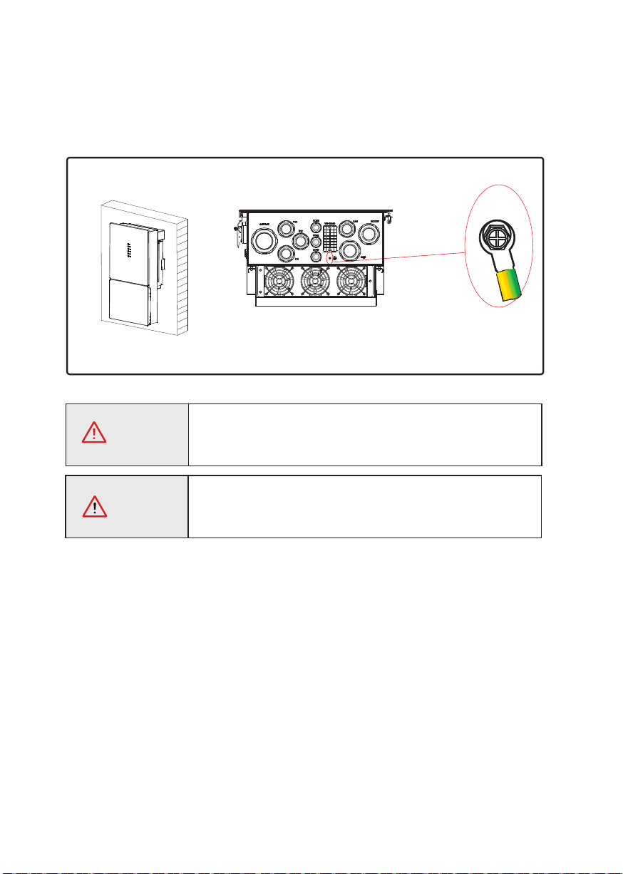
A protective earth (PE) terminal is equipped at the side of the inverter. Please be sure to connect this
PE terminal to the PE bar for reliable grounding. AWG 2 or 4 yellow green lines are recommended.
CAUTION
If the positive pole or negative pole of the PV array is required to
be grounded, then the inverter output (to AC grid) must be isolated
by transformer in accordance with IEC62109-1, -2 standards.
The inverter must be grounded; otherwise, there may be an electric shock
risk.
WARNING
Grounding
Terminal
The bottom view
4.1 Grounding
This manual suits for next models
3
Table of contents
Other Senergy Inverter manuals


Popular Inverter manuals by other brands

Fuji Electric
Fuji Electric Frenic Mega Series user manual

Omega
Omega OTEC IEWH Series Service manual

York
York YH9FXH24BAH--FX Service manual

Zipper Mowers
Zipper Mowers ZI-STE1100IV user manual

SOLIS
SOLIS Solis-1P6K3-4G Installation and operation manual

Mitsubishi Electric
Mitsubishi Electric FR-A8AX instruction manual


Dometic
Dometic TEC 40D Operation operating manual

Mitsubishi Electric
Mitsubishi Electric FR-A720-0.4K instruction manual

Generac Power Systems
Generac Power Systems Guardian 5340 Specification sheet

LSIS
LSIS LSLV-S100 Series manual

Hewalex
Hewalex KSOL-1 Manual of installing

Kaco
Kaco blueplanet 1502xi operating instructions