Senergy Natural cooling Series User manual
USER MANUAL
Three-Phase Grid-Tied Solar Inverter
30K/40K/50K/60K LV25/30/36K
Version: EN-UM-1.1

1.0 15-Jun.-23 First release
1.1 15-Nov.-23 Updated bracket in 3.1 Packing and 4.2 Mounting.
VERSION ISSUED COMMENTS
History
I

Preface
WARNING
CAUTION
DANGER
NOTICE
NOTE
Scope
Target Group
Inverters must be installed by qualified and professional electrical engineers.
Indicates a potentially hazardous situation which, if not correctly followed,
will result in serious injury or death.
Indicates a potentially hazardous situation which, if not correctly followed,
could result in moderate or minor injury
Indicates a potentially hazardous situation which, if not correctly followed,
could result in equipment failure, or property damage.
Call attention to important information, best practices and tips:
supplement additional safety instructions for your better use of the inverter to
to reduce the waste of you resource
Conventions
Indicates an imminently hazardous situation which, if not correctly followed,
will result in serious injury or death.
Natural cooling series Fan cooling series 1 Fan cooling series 2
30KTL-T3/K
30KTL-T3/G2
40KTL-T3/G2
25KTL-TL3
50KTL-Q3/G2
Fan cooling series 3
60KTL-Q3/G2
30KTL-QL3/G2
36KTL-QL3/G2
About This Manual
The following safety instructions and general information are used within this Manual.
This manual describes the installation, connection, the use of APP, commissioning and maintenance etc. of
the inverter. Please first read the manual and related documents carefully before using the product, and be sure
to store it in a place within the reach of installation, operation and maintenance personnel. The illustrations
in this Manual are for reference only. This Manual is subject to change without prior notice. (Specific products
in kind prevail.)
II

Preface
1. Safety
2. Product Introduction
3. Unpacking and Storage
4. Installation
5. Electrical Connections
About This Manual
Target Group
Scope
Conventions
1.1 Symbols Used
1.2 Safety Precautions
2.1 Overview
2.2 Product Appearance
3.1 Unpacking and Check
3.2 Storage Inverter
3.3 Identify Inverter
4.1 Selecting the Mounting Location
4.2 Mounting
5.1 Grounding
5.2 AC Connection
5.3 PV Connection
5.4 Communication Connection
CONTENTS
III

6. Startup/Shutdown Procedure
7. User Interface
8. Troubleshooting and Maintenance
9. Technical Specifications
6.1 Inspection
6.2 Startup Procedure
6.3 Shutdown Procedure
8.1 Inverter Troubleshooting
8.2 Maintenance
7.1 LED
7.2 LCD
IV
Before using the inverter, please read all instructions and cautionary markings on the unit and in this Manual.
Put this Manual in a place where you can take it easily. Our inverter strictly conforms to related safety
rules on design and test. Please follow local laws and regulations during installation, operation and
maintenance. Incorrect operation may cause personal injury or death and damage.
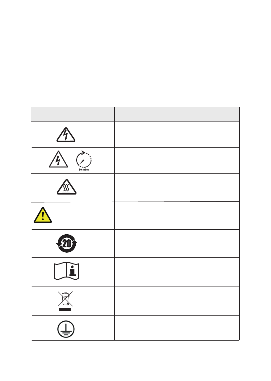
1.1 Symbols Used
Three-Phase Grid-Tied Solar Inverter 1
Safety
Danger of high voltage!
Only qualified personnel may perform work on the inverter.
Grounding terminal
Safety Symbol Description
Residual voltage exists after the inverter is powered off. It
takes 30 minutes for system to discharge to a safe voltage.
Danger of hot surface
Do not disconnect under load!
Environmental Protection Use Period
Refer to the operating instructions
Do not disconnect under load, otherwise there will be
a danger of fire.
Don’t dispose of the inverter with the household waste.
1 Safety

Installation, maintenance and connection of inverters must be performed by qualified personnel, in
compliance with the electrical standards, wiring rules and requirements of local power authorities
and/or companies.
To avoid electric shock, DC input and AC output of the inverter must be terminated at least 10 minutes
before performing any installation or maintenance.
The temperature of some parts of the inverter may exceed 60℃ during operation., so do not touch the
inverter during operation, otherwise you may be burnt.
Ensure children are kept away from the inverter.
Take appropriate measures to avoid electric shock.
Don’t open the front cover of the inverter. Unless performing work at the wiring terminal (as instructed
in this Manual), touching or changing components without authorization may cause personal injury,
damage to inverter and annulment of the warranty.
Ensure the output voltage of the proposed PV array is lower than the maximum rated input voltage of
the inverter; otherwise the inverter may be damaged and the warranty annulled.
When exposed to sunlight, the PV array will generate dangerous high DC voltage. So please operate it
according to our instructions, or your life will be in danger.
Do not insert or pull the AC and DC terminals when the inverter is running.
1.2 Safety Precautions
Safety
Three-Phase Grid-Tied Solar Inverter 2
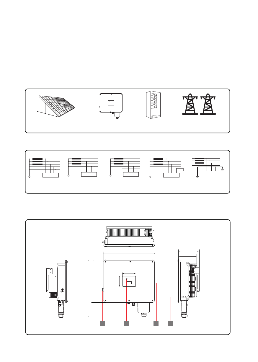
The three-phase grid-tied solar inverter converts the direct current (DC) generated by PV panels into three-phase
alternating current (AC) and is delivered to the grid.
This series of inverter is an important part of PV system and it is suitable for household use, commercial roof,
fishing light, and agricultural light and more scenarios.
The inverter supports five types of earthing system, including TN-S, TN-C, TN-C-S, TT, IT.
PV strings Inverter AC Distribution Unit Grid
TN-S
L1
L2
L3
N
PE
PE
Transformer
TN-C
L1
L2
L3
PEN
PE
TN-C-S
L1
L2
L3
N
PE
PE
TT
L1
L2
L3
N
PE
PE
Transformer Transformer Transformer
Inverter Inverter Inverter Inverter
IT
L1
L2
L3
N
PE
PE
PE
Transformer
Inverter
2 Product Introduction
2.1 Overview
Product Introduction
Three-Phase Grid-Tied Solar Inverter 3
The following figures are only for reference, specific products in kind prevail.
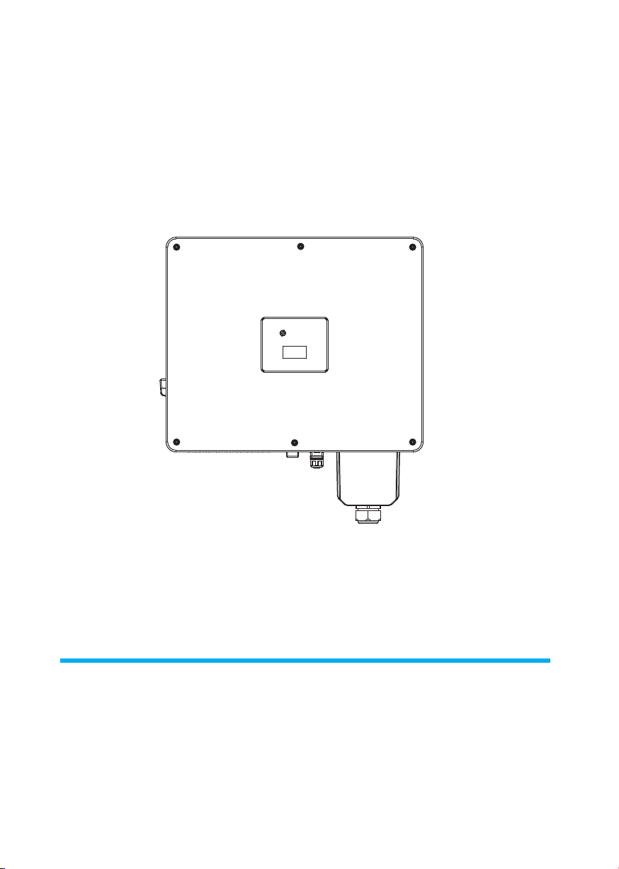
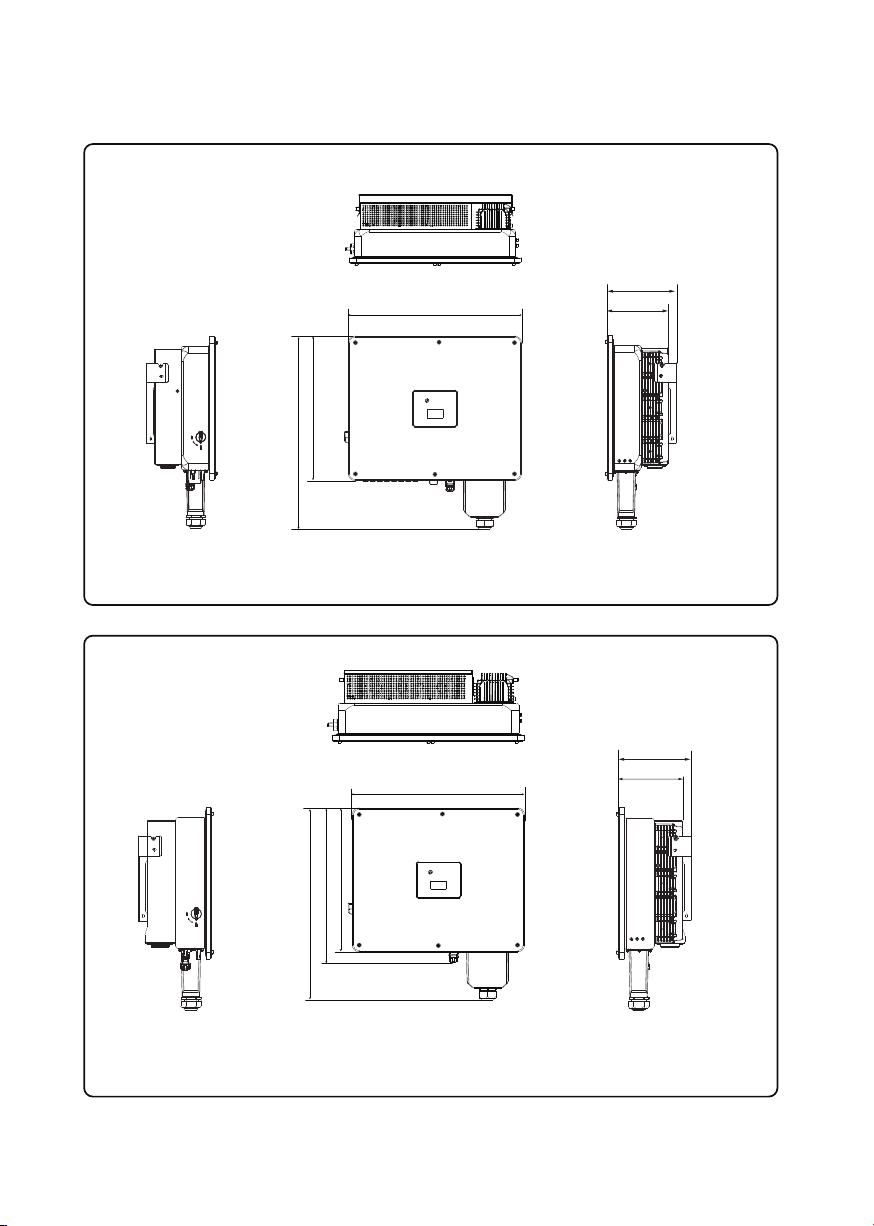
2.2 Product Appearance
221.8mm
253.3mm
635mm
530mm
707.5mm
30K:
23
14
160
130
ON
OFF
Product Introduction
Three-Phase Grid-Tied Solar Inverter 4
635mm
635mm
233mm
530mm
707.5mm
530mm
570mm
708mm
50K:
60K:
223.3mm
254.8mm
264.5mm

1 DC Switch
2 LED indicator
3 LCD Screen (optional)
4 External ground points
10
Natural cooling series Fan cooling series 1
Fan cooling series 2 Fan cooling series 3
5 7 8
Number Description
5 PV terminal
6 Vent valve
7 WIFI module communication port (COM1)
8 Reserved communication port (COM2/3)
9 RS485 communication port (COM4)
10 AC output port
11 External fan (It is only suitable for Fan cooling series)
Product Introduction
Three-Phase Grid-Tied Solar Inverter 5
11 9
6
Complete test and strict inspection before the inverter is sent out.
When receiving the inverter, check that the packing materials are intact.
After unpacking, examine the PV inverter and its fittings for damage and check that the deliverables are
complete.
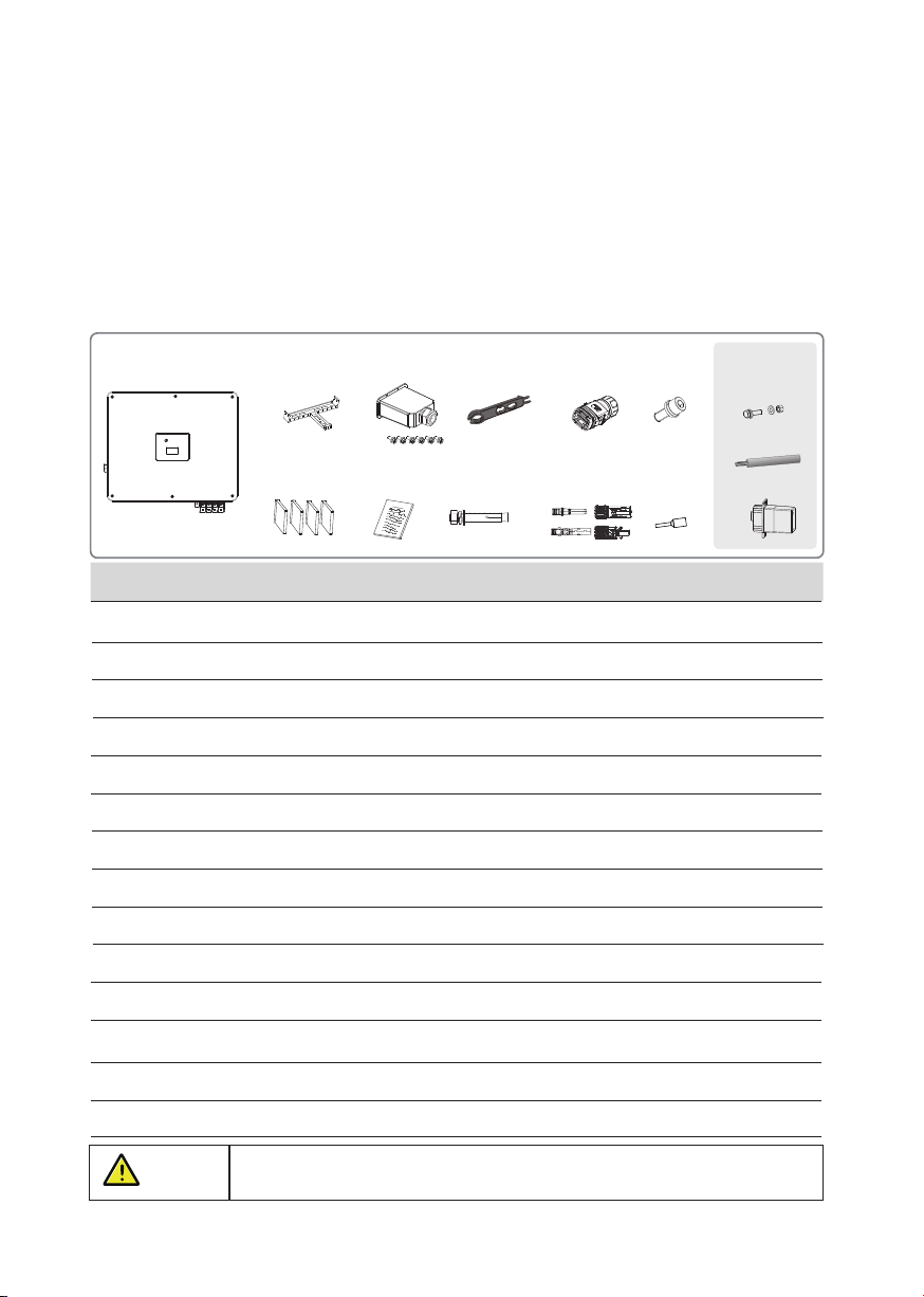
ABCD E F
GH I J K
L
M
N
Number
A Inverter
B Wall mounting bracket
C AC cover (with 6x M4 security screws)
D Tightening/Removal tool for PV connector
E RS485 terminal
F M6 Security screws
G AC inserting pieces
H File package
I M12 Expansion screws
J PV connector groups
NOTICE Contact your dealer immediately, if there is any issue found during operation.
3.1 Unpacking and Check
3 Unpacking and Storage
Unpacking and Storage
1
1
1
1
1
2
4
2
6 or 8
3
3 (optional)
Three-Phase Grid-Tied Solar Inverter 6
QuantityDescription
6x
Files
OPTIONAL
N WIFI/GPRS/4G module
M Handle tool
1 (optional)
2 (optional)
L M12 screws (only for bracket-mounted installation)
K Pin terminal 12
Three-Phase Grid-Tied Solar Inverter 7
If the inverter is not used immediately, please keep the inverter in a specific environment according to the
following:
Do not unpack the inverter and put desiccant in the original box if the PV inverter is unpacked.
Store temperature range: -25°C ~ +60°C; Relative humidity range: 0~100%.
When the inverter is placed multi-layered, it can be folded up to four layers.
Do not position the inverter at a front tilt, excessive back tilt, or side tilt, or upside down.
Ensure that qualified personnel inspect and test the inverter before use if it has been stored for a long time.
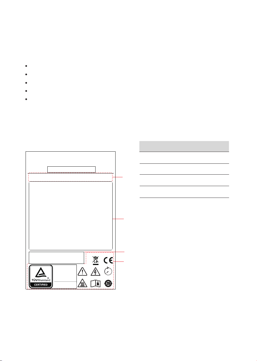
Inverter body label. The following is only for reference, specific please in kind prevail!
Number Description
1 Product name and model
2 Product technical parameters
3 SN Barcode
4 Approve and Safety identification
3.2 Storage Inverter
3.3 Identify Inverter
Product Introduction
1
2
3
4
www.tuv.com
ID XXXXXXXXXX
Type Approved
Safety
Regular Production
Surveillance
XXXX-XXXX-X
Model Name:
Product Model:
30 mi ns
d.c.Max.Input Voltage:
MPPT Voltage Range:
d.c.Max.Input Current:
d.c.Shorted Input Current:
a.c.Rated Output Voltage:
a.c.Rated Output Frequency:
Rated.Output Current:
a.c.Max.Output Current:
a.c.Rated.Output Power:
Rated Apparent Power:
Max.Apparent Power:
AC Overvoltage Category:
DC Overvoltage Category:
Inverter Topology:
Adjustable Power Factor Range:
Enclosure:
Temperature Range:
Protective Class:

Ensure there is no electronical connections around ports of the PV inverter before
installation.
DANGER
a. With an IP66 protection rating, the inverter can be mounted either indoors or outdoors.
b. To ensure optimum operation and a long service life, the ambient temperature must be below 50℃.
c. Do not install the inverter in a rest area since it will cause noise during operation.
d. The
carrier where the inverter is mounted must be fire-proof. Do not mount the inverter on flammable
building materials.
e. Ensure that the wall meets the requirements of the inverter installation.
f . Product label and warning symbols shall be clear to read after installation.
g. The installation height should be reasonable, and make sure it is easy to operate and view the display.
h. Please avoid direct sunlight, rain exposure, snow cover.
No direct sunlight No rain exposure No snow cover
Direct sunlight Rain exposure Snow cover
After checking the outer packing, move the PV inverter to the designated installation position horizontally.
CAUTION
1. Please place the inverter horizontally on the foam or other soft pads and ensure
that the ports are free of load-bearing pressure to avoid inverter damages or scratches.
2. The inverter is heavy, be careful to prevent the inverter from slipping and hurting
the operator when moving the inverter.
4.1 Selecting the Mounting Location
4.1.1 Installation Environment Requirements
Installation
4 Installation
Three-Phase Grid-Tied Solar Inverter 8
NOTE:
The following figures only illustrate the appearance of 50K inverter as an eample. Other inverter
models’ appearances will be marked if there are specific descriptions.

Upright Lean back ≤15° Horizontally
Mount the inverter vertically or tilted backward by max 15°. In order to facilitate the heat dissipation
of the inverter.
≤15°
Upside-down
Above: 600
Below: 600
Front: 1000
Both sides: 600
NOTICE A wrong installation mode would cause the inverter to be damaged or unable to work
properly.
To keep the inverter normal and easy to operate, the requirements for available spaces of the inverter must be
followed, e.g. to keep enough clearance. For details, see the following figures.
Unit: mm
Unit: mm
4.1.2 Mounting Requirements
4.1.3 Requirements for Installation Space
Installation
≥1000
≥600
≥600
≥600
≥600
Three-Phase Grid-Tied Solar Inverter 9
Installation along the same line for multiple inverters:
600 600

Installation perspective schematic:
Installation
Three-Phase Grid-Tied Solar Inverter 10
575mm
490mm
146mm
295mm
245mm
635mm
530mm
707.5mm
Step1 Use a level ruler to mark the positions for drilling holes on the installation site..
DANGER
4.2.1 Install the Mounting Bracket
1.The walls must be fireproof and non-flammable materials, otherwise there is a fire risk.
2.Before drilling holes ,check whether there are electric power pipes buried in the walls to
avoid risks.
4.2 Mounting
4.2.1.1 Wall-Mounted Installation
Step2 Drill 3 holes, 16mm in diameter and 55 mm in depth.
Ф
16 mm
Depth: 55mm

Installation
Three-Phase Grid-Tied Solar Inverter 11
Ф
14 mm
4.2.1.2 (Optional) Bracket-Mounted Installation
3x M12
26 N·m
Step3 Insert the expansion bolts into the holes and secure them with a hammer.
Then remove the nut, spring washer, and flat washer.
Note: Do not remove the nut before performing this step.
Step4 Fix the mounting-bracket wiht the expansion bolts. Screw:3*M12, torque: 26N·m.
Step1 Mark the positions for drilling holes on the installation site.
Step2 Drill 3 holes, 14mm in diameter.
Step3 Tighten the support and the rear panel with 3 sets of M12 screw kit.
(M12 x 80mm;3 sets)
3x M12
42 N·m
*
#
M12 : screws for bracket mounting.
M12 : expansion screws for wall mounting.
NOTE:
*
#
#

Hook the inverter into the bracket accurately and tighten the screws at both sides.
We recommend at least two persons to carry the inverter.
Three-Phase Grid-Tied Solar Inverter 12
Installation
Handle tool is optional.
4.2.2 Install the Inverter
min. 2
To prevent damage of the inverter, please hang the inverter on the bracket
and confirm the reverse, do not loosen the handle until the inverter is fixed.
CAUTION
Two sides
2x M6
3 N·m

System Connection
PE
DANGER
Grid
PE
Breaker
N
L3
L2
L1
PE
PV+
PV-
Before electrical connection, please ensure
that both the AC and DC ends are powered off,
otherwise there will be a high voltage shock.
5 Electrical Connection
Three-Phase Grid-Tied Solar Inverter 13
Electrical Connection
NOTE:
The cable colors in figures are only for reference. Select appropriate cables according to the local
standards.

M6 x12mm
3 N·m
CAUTION
According to regulations, the secondary protection grounding can’t replace the PE
terminal connection of the AC cable. Ensure that both are grounded reliably;
otherwise, fatal injury can occur due to the high voltage.
WARNING
If the positive pole or negative pole of the PV array is required to be grounded,
then the inverter output (to AC grid) must be isolated by transformer in accordance
with IEC63109-1,-2 standards.
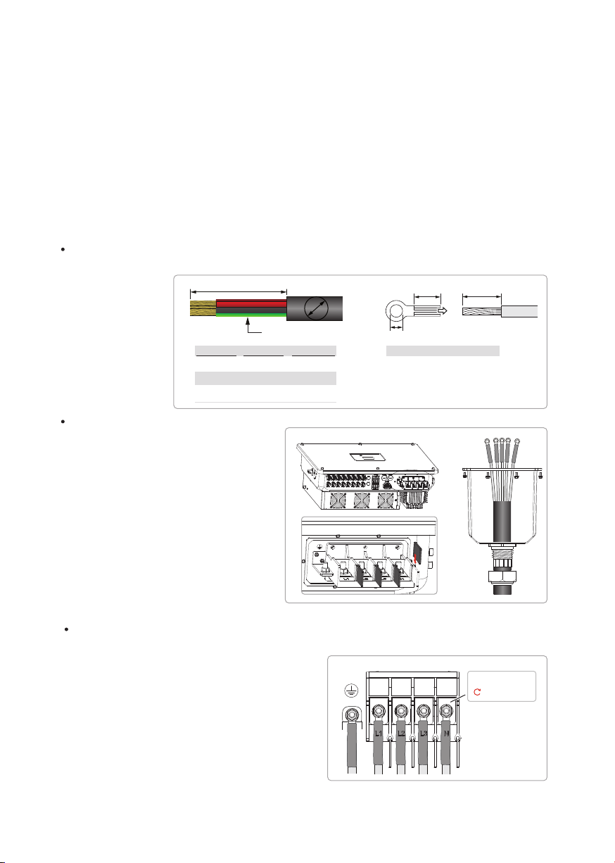
Step2 Insert the exposed core wires into the crimping areas of the OT terminal and crimp them using
hydraulic pliers.
Step3 Remove the ground screws from the ground points.
According to the EN50178 requirement, the right side of the device has a protective grounding connection.
Be sure to connect the protection ground cable to this port when installing the inverter.
Users should perform the ground connection according to the on-site condition.
5.1 Grounding
L1
L2=L1+ (2mm~3mm)
L3<2mm
L4<(0mm~1.5mm)
Three-Phase Grid-Tied Solar Inverter 14
Electrical Connection
Reserved PE point
Recommended OT Terminal: OT16~25-6
Step1 Remove an appropriate length using a wire Stripper.
5.2 AC Connection
1. Measure and access the voltage and frequency of the point to ensure that it meets the grid-tied
specifications of the inverter.
2. PE wire (GND) must be well grounded to ensure that impedance between Neutral wire and Earth
wire is less than 10Ω.
3. Disconnect the circuit breaker or fuse from the inverter and grid-connected access point.
4. Use the copper wire.
5. Follow the steps below.
5.2.1 AC cable connection
Note:It is recommended to use outdoor dedicate cables with multiple copper cores.
Step2 Wires threading and pressing.
Step3 Lock the AC cable to corresponding AC terminals. Screw: 5*M8, torque:10 N·m
Three-Phase Grid-Tied Solar Inverter 15
Electrical Connection
100 mm(recommended)
BA
L1 L1 + 2 mm
M8
· Insert AC separators
· loosen the cable gland and thread the AC
cable (5 wires) cross the gland, threaded
sleeve and the AC cover. Then crimp the OT
terminal and use heat shrink tubing or
insulation tape for protection.
PE
10 N·m
5x M8
Step1 Select proper AC cables and OT terminals (5 wires), and strip cables.
A
Model
40K/LV25K
50/60K
LV30/36K
30K 25...31 mm
32...38 mm
32...38 mm
16...35 mm²
25...50 mm²
35...50 mm²
BRecommended OT Terminal:
30K: OT16~35-8
40K/LV25K: OT25~50-8
50/60K/LV30/36K: OT35~50-8
This manual suits for next models
11
Table of contents
Other Senergy Inverter manuals


Popular Inverter manuals by other brands


BARRON
BARRON EXITRONIX Tucson Micro Series installation instructions

Baumer
Baumer HUBNER TDP 0,2 Series Mounting and operating instructions

electroil
electroil ITTPD11W-RS-BC Operation and Maintenance Handbook

Silicon Solar
Silicon Solar TPS555-1230 instruction manual

Mission Critical
Mission Critical Xantrex Freedom SW-RVC owner's guide

HP
HP 3312A Operating and service manual


